

FM 34-80: Brigade And Battalion Intelligence and Electronic Warfare Operations
APPENDIX C
THE SURVEILLANCE CARD
The preprinted surveillance card is a reusable plastic device used to record temporary information about target areas for preplanning surveillance and to record data concerning targets detected during normal operations of the radar site. By using the mil scale around its outer edge and the attached pivot al range arm, you can also use the card to determine exact locations of targets quickly and accurately. The card is to a scale of 1:50,000 and can be easily fabricated at the radar section level if the preprinted card is lost or mutilated. Normally, the surveillance card is prepared by the senior operator or the team chief from information furnished by the S2, section leader, or platoon sergeant. Surveillance cards should be prepared for primary, alternate, and supplementary radar sites. They should be transferred to the new unit when you are relieved in place by another radar team. This will save them the trouble of preparing a new surveillance card for the same area.
ORIENTING THE SURVEILLANCE CARD WITH A COMPASS
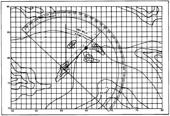
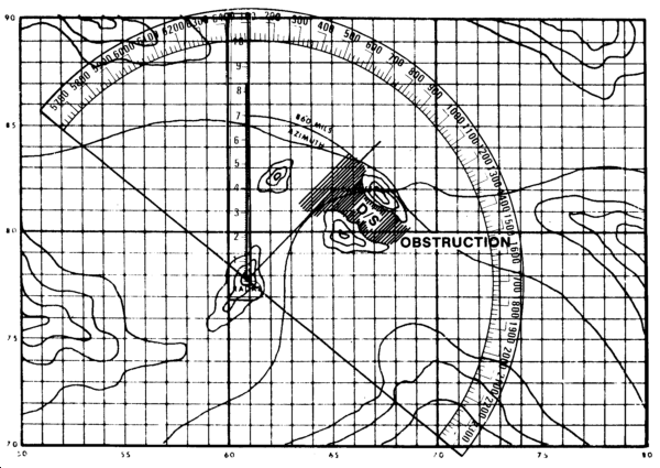
STEP 1
Determine the 6-digit coordinate of your radar location and mark it on your map with a dot. Select a target in the center of your surveillance area and mark it on your map. With your compass, measure the azimuth to the target (860 mils magnetic).
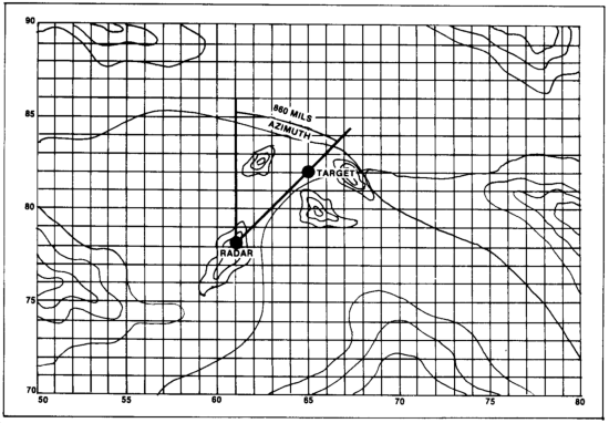
NOTE: All azimuths used are grid azimuths. Therefore, all compass readings must be converted from magnetic to grid azimuth.
STEP 2
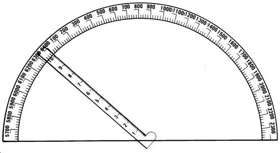
On your surveillance card, write 8 before the two zeros in the center at the top of the card.
STEP 3
Number the even hundred mil marks around the edge of the surveillance card. Begin, clockwise. with 9. which indicates the next hundred or 900 mils and continue. Counterclockwise enter 7 on the first hundred mil tick mark and compute all numbers on the card.
STEP 4
Align the range arm on 860m (azimuth to the target). Since each small tick mark is 20m, the range arm should be three small tick marks past 800m.
STEP 5
Place the surveillance card over the map, aligning the hole at the base of the pivot arm over your site. Rotate the card until the range arm is aligned with the target. Be careful that the range arm stays on 860m and the hole remains over your radar position.
STEP 6
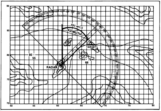
Tape the overlay to the map. Draw your reference marks on the overlays so that the overlay can be removed and reoriented. On the right and left sides of the overlay outside the surveillance area, find a north/south and east/west grid line cross. Trace over these lines to form a small cross about one-inch long and one-inch wide. At the top or bottom of the north/south grid line write the 2-digit number of that grid line. At the left or right of the east/west line write the 2-digit number of that grid line.
STEP 7
Check the orientation of the overlay by shooting two or three more azimuths to objects that are shown on the map. Convert them to grid azimuths. Move the range arm until it is over the object on the map and read the azimuth that you shoot for each object. This reading should be within 10 mils of the azimuth that you shoot for each object. If not, do the orientation procedures again and recheck.
ORIENTING THE SURVEILLANCE CARD WITHOUT A COMPASS
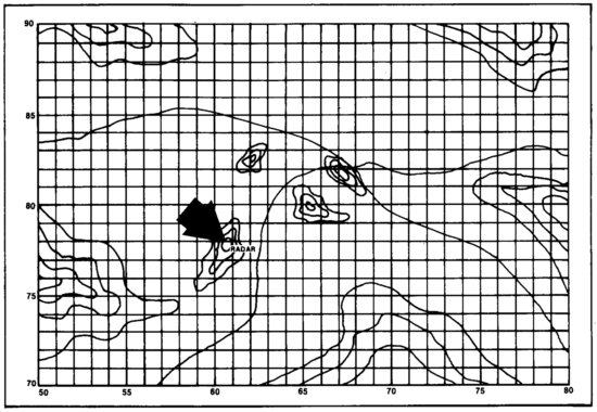
In most instances the general site and sector to be covered will be designated by the supported unit. In all cases, the LEFT and RIGHT limits of your sector must be determined prior to mounting the surveillance card on your map.
MOUNTING THE SCAP
The following steps will allow you to mount your surveillance card and plotter (SCAP) quickly and accurately.
Step 1
Perform a resection and plot this location on your map.
Step 2
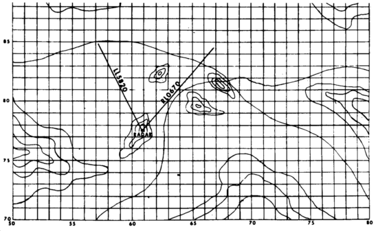
Plot the LEFT and RIGHT limits of your sector on your map.
Step 3
Place your SCAP on the map.
a. Locate the SCAP pivot point directly over the radar location.
Rotate the SCAP until your surveillance area is centered in the SCAP target area.
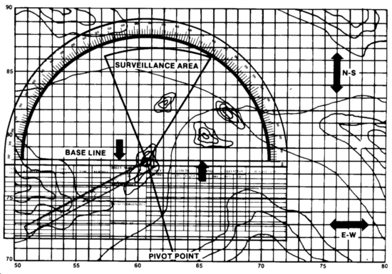
b. Now rotate the SCAP, lining the BASE LINE up parallel with either a NORTH-SOUTH or an EAST-WEST grid line.
The surveillance area MUST remain inside the SCAP target area, though it does NOT have to be centered.
Step 4
Tape the SCAP to the map. While doing this, ensure the pivot point remains over the radar location AND the base line remains parallel to the grid line you used to orient the SCAP.
Draw reference marks on the SCAP so it can be removed and remounted. On the left and right sides of the plotter outside the surveillance area, locate a grid line intersection. Trace over this grid line to form a cross about one inch long and one inch wide. At the bottom of the north-south grid line you have drawn, write the 2-digit number of the grid line.
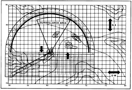
Step 5
Check the orientation of the plotter by shooting two or three azimuths to objects shown on the map. Convert these azimuths to grid azimuths.
Swing the range arm to a position over the object on the map, and read the azimuth. This azimuth reading should be within 10 mils of your compass reading. If not, do the orientation procedures again and recheck.
Step 6
Complete your SCAP by filling in the dead spaces, writing in the correct numbers in the azimuth ring, and completing the preparation data. Mark the predetermined point, area, and sector targets in the surveillance area and enter the appropriate information in the legend.
If the supported unit has given you specific targets, plot and number these targets on the SCAP. The symbols below will be used to indicate the type of target:
- POINT TARGETS--A point-type target is recorded by making a dot at the point of interest and numbering this line. Indicate this target in the legend using the same number.
EXAMPLE: 
- AREA TARGETS--An area-type target is recorded by drawing a line over the area and numbering this line. Indicate this target in the legend using the same number.
EXAMPLE: 
- AREA TARGETS REQUIRING A CHANGE IN RANGE--Some area targets require a change in range or a change in azimuth. The area target symbol used above remains the same.
EXAMPLE: 
RECORDING INFORMATION
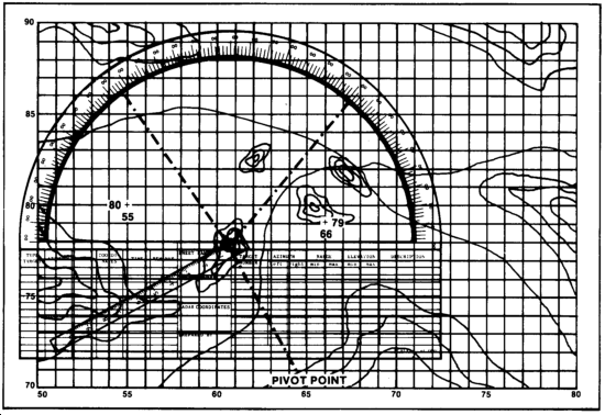
Target numbers. Target numbers should coincide with the number assigned to the target by the S2.
Azimuths. Enter the azimuth or azimuths required to orient the radar toward the target or area. If it is a point-type target, one azimuth will be required. Area-type targets, such as a stretch of road, will require both the right and left azimuth covering the area.
The single azimuth of a point target is determined by aligning the range arm over the target and reading the azimuth at the top of the surveillance card. This azimuth is then recorded in the legend. The area-type target, which requires two azimuths, is determined by using the range arm to the right and left limits of the area. These azimuths are then recorded in the legend.
REMEMBER: The long marks represent 100 mils and each short mark represents 20 mils. A high degree of accuracy (to within 10 mils) can be determined.
Ranges. Next, enter the range or ranges required to survey the point or area. The range is obtained by aligning the range arm over the target area and reading the distance marked on the range arm. The arm is numbered from 1 to 10; each number represents 1,000 meters and each tick mark represents 100 meters.
In some instances, while monitoring a point, you may have to make range changes. This is determined by measuring the minimum and maximum ranges which can be adequately covered in the area.
Elevation Settings. The elevation setting is determined by aligning the telescope of the radar on the target or area and reading the elevation. In hilly terrain, you may require more than one elevation setting for each target or area. When these readings are determined, enter the minimum and maximum elevation in the legend.
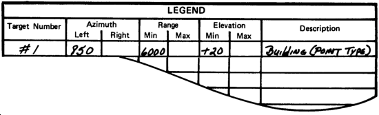
Description. Enter the type and frequency of surveillance for the point or area or any other information that is required.
Other uses. The surveillance card overlay can also be used to record dead space that cannot be covered by your radar. If there is a hill that blocks your LOS, record this on your overlay.
Coordinates. With the surveillance card, you can determine the 6-digit coordinate of a target in about 20 seconds. Take the target azimuth and range from the radar. Set the range arm on the correct azimuth and go out the arm to the proper range. Mark the target's position on the overlay and, using a coordinate scale, read the 6-digit coordinates from the map.
Surveillance area. Use a compass or map to determine the right and left limits of your surveillance area. Once you have determined the grid azimuths of the left and right limits, align the range arm on those azimuths and draw a line from your radar position to the azimuth marks.
Targets data log. The data log is used to record information about targets or areas of interest not listed in the legend. It is also used as a record of targets detected and reported.
POINTS TO REMEMBER
Each small tick mark represents 20 mils.
Each large tick mark represents 100 mils.
Be sure to recheck your orientation by shooting two or three more azimuths to objects shown on your map.
All magnetic azimuths must be converted to grid azimuths.
Be careful that the pivot point hole and range arm do not move when working with orientation.
Be simple, accurate, and fast.
|
NEWSLETTER
|
| Join the GlobalSecurity.org mailing list |
|
|
|