| Chapter Five. Construction |
5-1. Introduction. Military pipeline construction is a very labor- and equipment-intensive mission. When logistics planners determine that a military pipeline is required, equipment and labor support must be allocated in sufficient quantities to meet the required rate of construction. Additional material-handling equipment and transportation assets, not within the engineer organizations, must be allocated to move, load, and unload pipeline materials from the port of entry to the construction staging areas.
A platoon can construct about 1 1/2 miles of coupled pipeline per day, based on terrain and obstacles they must cross. On flat terrain with limited obstacles, a highly trained crew can lay up to 2 miles per day. In mountainous terrain with numerous obstacles, the same crew may be able to construct only 1/2 mile per day. The main factors to consider in estimating rate of construction are terrain, obstacles, weather, tactical situation, and location of the construction staging areas and construction access road to the pipeline route.
a. Task Organization for Construction. The organization of a unit indicated by its table of organization is a generalized concept. Many minor changes must be made to effectively use the available skills for a specific job or project. A pipeline construction support company is designed to provide technical expertise to a battalion-size, engineer construction unit for pipeline construction. The general construction unit can be made up of either troop or civilian labor. The design rate of construction will determine the task organization between the specialized pipeline construction company and the general construction unit. The general command structures of both units should be retained, as much as possible, to ensure maximum command and control. For example, a general engineer platoon could be assigned a pipeline construction squad for technical expertise.
b. Construction Standards. Military pipeline-construction standards must be established and met from start to finish. Pipeline failure has serious consequences. Fuel loss or delay of its supply can disrupt combat operations. Avoidable repair or reconstruction wastes time, troops, and materials that could have been used elsewhere.
Taking time to correct past mistakes may mean that the pipeline does not keep pace with advancing combat operations. Troops may have to use trucked-in fuel. They could eventually outstrip the pipeline or run out of fuel. Repairing a leaking or broken pipeline can be extremely hazardous and life-threatening. Detailed fire-prevention precautions are necessary, requiring a disproportionate amount of military effort. Miles of pipeline may have to be drained into tank trucks or into hastily excavated sumps. The environmental impact of such activities must be planned for. Main supply routes adjacent to the pipeline may have to be blocked to facilitate the repair. The following are the minimum standards for military pipeline construction:
(1) Pipes. Keep pipes clean and free from debris at the time of construction. Small quantities of loose material in each pipe length can accumulate in sufficient volume to clog sand traps or strainers located at pumping stations. Before coupling or welding pipe lengths together, inspect them for cleanliness inside and out. Run a swab or wire brush through each length to clean out any debris just before connecting it to the line. Aluminum pipes are equipped with end caps that should remain in place until the pipes are coupled. Discard any badly corroded pipes.
(2) Pipeline Components. Each connection in the pipeline should stand up to the design pressure without leaking so that the agreed-on, allowable, product loss rate can be met. With coupled connections, the coupling will leak if the pipe ends, gaskets, or the couplings themselves are defective, damaged, or dirty.
(a) Pipe ends. Inspect pipe ends for dents, out-of-roundness, paint, scale, rust, or other irregularities. The pipe end (land end) must be smooth and within 1/32-inch round for a tight joint. (In the field, you cannot hammer or sway back into shape any ends that are dented or bent out-of-round.) Remove all loose paint and scale from the nipple ends; file off any burrs or rough edges. Make sure you keep nipple lands, gaskets, and coupling halves clean throughout the coupling operation.
(b) Coupling gaskets. Coupling gaskets must fit smoothly inside the coupling halves. Discard any gasket that shows signs of age (excessively hard, cracked, or cut).
(c) Couplings. Inspect couplings for any cracks or gouges due to rough handling. A damaged coupling will not withstand the pressure that a coupled pipeline is designed for.
(d) Hose line. Inspect all hose lines for dry rot. Do not use a hose line that has dry rot.
5-2. Coupled Pipeline Systems.
a. Coupling Procedures for 6-Inch Aluminum Pipe and 4- and 6-Inch Steel Pipe. For military use, coupled pipelines are preferred over welded pipelines because they can be constructed quicker. To couple pipe sections together, groove the pipe ends to facilitate a coupling and gasket assembly. Grooved pipe is available in standard-weight and lightweight steel and lightweight aluminum. (The lightweight pipes are also referred to as tubing.) See Chapter 2 for more information on pipeline components. Use the following procedures when coupling a pipeline using 6-inch aluminum pipe or 4- and 6-inch steel pipe:
(1) Stake Pipeline Route. Marking crews, working ahead of construction crews by at least one day, stake out the final location of the pipeline and its installations using wooden stakes. If clearing and leveling are required, they must mark the route in advance. These markers should be visible, one from the other, at maximum intervals of about 500 feet. The crew leader should be experienced in pipeline construction. Good layout can greatly reduce the construction effort. Markers can be color-coded to furnish detailed information to construction crews. Table 5-1 lists suggested stake colors for various types of installations.
(2) Clear and Level Pipeline Route.
(a) Clearing. Clear the pipeline route just enough to get the line laid efficiently and permit patrolling. Keep clearing to a minimum to save time and maximize natural vegetation for camouflage. Clear enough vegetation so it does not restrict operations. Use a 4-ton bolster trailer pulled by a 5-ton truck to get pipe to the ground efficiently. The cleared route should be just wide enough (about 25 feet) for construction vehicles to gain access and for the pipe to be unloaded. Two-way traffic will require additional space.
Vegetation type and construction method determine the extent of clearing necessary. Areas containing dense growth usually require more clearing than forests containing large trees. In dense areas, the pipe sections cannot be aligned, and the construction crew has insufficient working space unless a lane is cleared through the areas. Forests that have large trees usually have very little undergrowth. Laying the pipeline between the trees should be possible. The construction crew will have to string the tubing sections manually. However, the total effort and time required may be less than that required to cut a trace through heavy stands of large timber.
When working in heavy forests, the crew should use farm access roads or old logging trails when off-loading pipe to reduce the distance that pipe must be carried manually. In an open field with high vegetation, mark the line adequately with signs to prevent damage by cross-country traffic.
(3) Determine Valve Locations. Gate, check, and vent valves are the most common valves installed in a pipeline system. The number and location of each must be predetermined, so sufficient quantities can be pre-positioned at construction staging areas that will supply that section of the pipeline.
(a) Gate valves. These valves are located at intervals in the pipeline for repair purposes. The number and location are based on the tactical situation. Pipeline lengths that are susceptible to damage, such as by bridges, should be isolated at each end by a gate valve. When enemy activity is anticipated to be low in the theater rear area, gate valves are installed about one every mile. Gate valves should be accessible from the road.
(b) Check valves. These valves are placed in the line at the bottom of steep upgrades to prevent backflow in case of shutdowns. When enemy activity is anticipated to be low in the theater's rear area, check valves are installed about every three miles.
(c) Vent valves. These valves provide an outlet for air in the pipeline. They are installed about every mile at the top of the highest terrain.
(4) Construct Pipeline Obstacle Crossings. Try to avoid major obstacles, such as steep cliffs, deep ravines, large boulders, and swampy areas, when selecting the pipeline route. Use existing road culverts whenever possible. Crossing obstacles can significantly slow down the construction rate. If an obstacle crossing facility must be constructed, it should be completed before the coupling crew completes the line to that point. This will eliminate the need for the construction crew to return to the site later to connect the line. If the line is constructed after the obstacle-crossing device is built, a custom-cut piece of pipe (pup joint) will be required. Each pup joint must be cut and grooved on each end, which takes a trained operator about 60 minutes. Pup joints should be made at a central location, like the construction staging area, to reduce the setup time required.
Studying maps and aerial photos when planning the pipeline route can help reduce the number of crossing sites. It may become necessary to traverse pipeline obstacles such as roadways, rivers, streams, and drainage ditches. Aluminum pipelines must be supported at least every 19 feet. The maximum unsupported span of steel coupled pipelines should not exceed 40 feet. The following obstacle-crossing kits are available through AFCS:
(a) Nestable culvert material. The best way to cross a road with pipeline is through an existing culvert. The 5-mile pipeline set has nestable culvert material. It should be installed to the same standards as a culvert installed for drainage. Steel sleeves can be used instead of nestable culvert. They do not have to be assembled, but they do require additional transportation and material handling equipment.
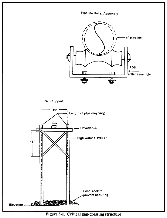
(b) Gap support structure with pipeline roller assembly. This structure and assembly (Figure 5-1) is used for crossing small streams and gullies. It consists of 4-inch diameter steel tubing and angled steel and roller assemblies. The rollers are installed so the pipeline can move during expansion and contraction. The structure must be fabricated on-site and is placed at intervals equal to the length of a stick of pipe, with the coupling positioned directly between the structures. Expedient gap-crossing structures (Figure 5-2) may be required if kits are not available.
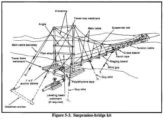
(c) Suspension-bridge kits. These kits (Figure 5-3) are available in 100-, 200-, and 400-foot spans. Detailed assembly instructions come in the packing list for each kit. If suspension kits are not available, expedient-crossing structures can be constructed.
(5) Prepare Construction Staging Areas. The construction staging area receives, accounts for, and issues construction materials. The location and operation of staging areas are key to maximizing the rate of pipeline construction. Pipeline components are moved from a central location to the construction staging area by stake and platform (S&P) trucks or similar means. Pipeline components are moved from construction staging areas by bolster trailers. Using a 5-ton cargo truck with a 4-ton bolster trailer is the best way to transport pipe sections from the construction staging area to the pipeline trace. (Using a 5-ton bridge truck is second choice.) A bolster trailer can holdup to 50 pieces or sticks of 19-foot, 6-inch diameter aluminum pipe when extensions are installed on standard stanchion assemblies. Be careful when loading and unloading bolster trailers holding more than 35 sticks of 6-inch pipe because of the height that you must lift the pipe when loading and unloading.
As the intermediate transfer point of pipeline components, the construction staging area reduces the turnaround time required for the movement of pipeline components to the trace. A constant supply of pipeline materials to the stringing and coupling crews is the key to maximum laying rates. Construction staging areas should be located about every 10 miles along the pipeline route. Each area must be large enough (about 100 yards by 50 yards) to store pipeline components and allow for loading operations.
Loading crews should not accompany the transport vehicles to the construction staging area. All loading operations at the construction staging area should be accomplish by a dedicated crew who will remain at that area. The crew size will depend on factors such as the number of stringing crews that it is servicing and the type of terrain on which the pipe is being constructed. Normally 10 to 12 soldiers are required, including equipment operators.
You will need at least one 10,000-pound, rough-terrain forklift to operate the staging area. Based on the required construction rate, more than one staging area may be operational at the same time. The layout of components within the staging area is a key factor in determining expedient loading and unloading. The following guidelines apply:
- Keep vehicular traffic flow one way within the staging area.
- Do not handload any aluminum pipe or steel tubing sections larger than 6 inches and standard-gauge steel pipe larger than 6 inches.
- Load couplings and valves at the same time as pipe sections. (You may have to improvise regarding a container for couplings.)
(6) Assign Crews to Pipeline Construction Areas. Pipeline stringing and coupling crews are assigned sectors along the pipeline trace. The size of the sectors will depend on the number of pipeline construction crews available and the number and size of construction staging areas that can be operated effectively at the same time. For example, if you have two operating staging areas with 10 miles of components each and five available crews, each crew would have a 4-mile sector or 20 miles divided per five crews. After a crew is finished in its sector, it is assigned a new one.
(7) Place Pipes and Valves. Off-loading and placing pipe sections along the pipeline route end to end is known as stringing. Two soldiers can off-load 4- or 6-inch diameter steel or aluminum tubing sections. Manually stringing 6-inch (170-pound) pipe is hazardous work. Normally, eight men are required to properly string such pipe. If the tubing sections have to be carried farther than 25 feet, more men are needed.
The stringing crew is made up of three teams of two soldiers each who move pipe from the bolster trailer to the ground; one soldier places coupling materials, the other is a supervisor/ground guide. The crew down loads pipe as the truck moves slowly along the trace.
|
WARNING Be very careful when stringing pipe at night. Soldiers could be injured by a moving truck. |
As the crew unloads each section, they place it end to end in close alignment with the preceding section. A coupling and a gasket are placed close to each end-to-end junction. The crew off-loads an extra tubing section for every 50 to 75 sticks. This section will be a replacement for a damaged section or a filler for any gap that may develop. Laying the extra section saves time. These sections can be recovered later if they are not used.
The crew chief should be experienced in coupling operations so he can envision the final position of the pipeline. His experience will help prevent a situation such as laying pipeline on the wrong side of a tree.
When stringing aluminum pipeline, expansion loops must be laid out for at least every 1,000 feet of pipeline. There should be enough vehicles assigned so that the stringing crew always has a vehicle waiting to be unloaded. Rehandling pipe should be avoided as much as possible. However, some rehandling may be unavoidable when terrain conditions prevent vehicles from following the pipeline trace. If this occurs, the stringing crew may have to create roadside stockpiles as close as possible to the route and then reload the pipe on 1 l/4-ton trucks or carry it by hand to the trace. In very difficult terrain, helicopters, beasts of burden, or indigenous civilian labor may have to transport pipe to the trace.
The supervisor must carefully monitor the soldiers as they unload, string, and couple the pipe sections together so they do not--
- Damage the land surface on the nipples (the pipeline will leak).
- Shove tubing sections or grooved pipe off the rear of a vehicle.
- Hold onto the rear end and let the vehicle pull ahead until the forward end drops off the vehicle.
- Throw or drop sections over the side.
- Throw or allow sections to roll down embankments.
- Raise the front end of the truck or execute a jackrabbit start, which causes the load to slide off the rear.
Check valves and gate valves are the most commonly used valves along a pipeline. These cannot be manually down loaded safely. A 7 1/2-ton crane or a SEE is best for this task. Valves are normally positioned just before the pipe is coupled at that location.
(8) Couple the Pipeline. Coupling pipe sections together is the most critical task in pipeline construction. Coupling is a time-consuming and strenuous task. If done incorrectly, the pipeline will leak under pressure. Repairing a leaking pipeline is a time- and labor-intensive task and should be avoided. The most common cause of a leaking joint is a pinched gasket, which is normally the result of hasty construction. See Chapter 6 for repair procedures. If sufficient coupling crews are available, coupling operations can be carried out in several sectors simultaneously.
Coupling on a downhill slope usually requires more effort than on a similar uphill slope. A highly trained crew can couple up to 2 miles per day of 6-inch pipeline over flat and clear terrain. The coupling crew should consist of seven soldiers. Their jobs differ depending if they use bolted or snap-joint couplings. When using snap-joint couplings, the crew consists of a crew leader, gasket greaser, front stabber, back stabber, coupler, coupler's helper, and a pinman. The crew will normally require the following tools and equipment:
- Two pipeline jacks.
- Assembly tool.
- Brass hammers.
- Drift pin.
- File.
- Two end caps.
- Half-gallon bucket filled with general agency agreement (GAA) grease.
- Cleaning rags.
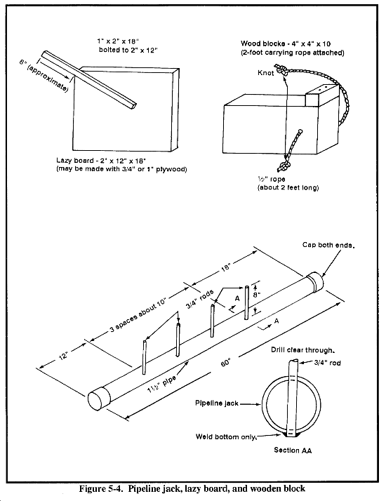
Depending on the terrain and job assignment, the crews may need additional equipment, such as crowbars, brush hooks, axes, machetes, saw, shovels, hand auger, hatchet, large nails, long bolts, and crescent or open-end wrenches. The pipeline jacks, lazy boards, and wooden blocks are field-fabricated (Figure 5-4). All other tools come in the grooved-coupling, pipeline-construction tool kit or as part of the component packing list. To couple pipe--
(a) Grease the gasket lightly and place it in a clean location. Do this just before coupling the pipe ends together to avoid getting dirt on the greased gasket. (Dirt or sand on the gasket can cause the joint to leak under pressure.) Place the complete coupling assembly, to include the gasket, directly next to the joint to be connected.
(b) Place the greased gasket over one end of a pipe section you will join. Do not fold the inside gasket flaps over because a leak could result.
(c) Position the pipe ends together. It is important that you line up the pipe ends and that they remain in this position until you close the coupling completely. Unit-fabricated pipe jacks and wood blocks can make this task less strenuous. Figure 5-4 shows these two items.
(d) Adjust the gasket over both pipe ends centered on joint. Do not fold the inside gasket flaps over; the joint could leak.
(e) Seat the coupling in bottom grooves of pipe.
(f) Close the snap-joint coupling, or install the top half of a bolted coupling in the top grooves of the pipe. Make sure that you position the gasket properly inside the coupling and that the joints of the snap coupling are not pinching the gasket. A pinched gasket will ALWAYS LEAK and will require replacement. After the snap coupling is closed, but not pinned, you should be able to hold both of the hinges and rotate the coupling back and forth. Doing so will help position the gasket in the coupling.
(g) Close the coupling halves together completely. (On older couplings, use bolts; on newer couplings, use an assembly handle.) The assembly handle should close the coupling smoothly with minimal pressure. The assembly handle will not close easily if the gasket is positioned incorrectly inside the snap-joint coupling. If you feel resistance, do not force the handle shut. Reposition the gasket and try to close the coupling again. If repeated attempts do not work, use a new coupling. (During this procedure with the snap-joint coupling, the gasket is most susceptible to damage by pinching.)
(h) Insert a retaining pin in the closed hinge of the snap-joint coupling and drive the pin into place. A sparkless brass hammer is in each box of couplings. Use this hammer when fuel is in the area; otherwise, you can use a 3-pound hammer.
(9) Align the Pipeline. The relative position of one pipe length to the next is pipeline alignment. Because aluminum pipeline systems expand and contract, deflection must be less than 2 percent. This allows the pipeline to push and pull itself without causing undue strain on any joint. For example, 50 joints of aluminum pipeline increase in length by 15 inches with a 100° F rise. The assembled coupling joint has a designed free deflection (without strain) of 4 percent. The installed deflection is limited to 2 percent, leaving room for some additional deflection during operation. You can field-fabricate coupling deflection templates to check alignment. If the ends of a two-length section are not outside each others radius, the pipeline is within required deflection tolerance.
You may have to use sandbags to level an aluminum pipeline system. (You do not have to level a steel pipeline system.) Place sandbags no closer than 2 feet from a coupling point. This allows for expansion and contraction. When stacking sandbags, make sure that they will not fall over during pipeline movement. To stack sandbags properly, build a large base and work-up to a small top where the sandbag meets the pipeline. Avoid stacking sandbags higher than four levels. Properly grading the pipeline route before construction starts can save time and manpower when leveling.
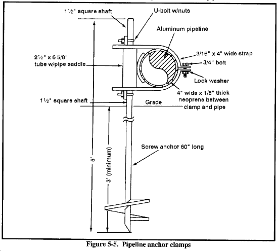
(10) Anchor the Pipeline. Because anchoring is not a manpower-intensive task, a long length of pipeline is constructed before anchoring is required. The anchoring crew is usually a two-soldier team. They should anchor every 1,000-foot section of aluminum pipeline midway between the expansion loop. Doing so allows for expansion and contraction due to temperature and pressure. Paragraph 5-2b discusses expansion devices. The crew installs a screw-type anchor (Figure 5-5) using a hydraulic drivehead attachment that can be put on a JD410 or a SEE boom. The coupling-crew leader should establish a method of marking the pipeline for anchor installation. After installing the anchor, the crew connects it to the pipeline with a metal clamp lined with a piece of rubber. They must be careful not to move the pipeline out of alignment during the anchoring procedure.
(11) Fill and Test the Pipeline. Before fuel pumping starts, military pipelines must be inspected and pretested to locate and repair leaks, obstructions, and other flaws in construction. Fuel could be wasted if this procedure is not followed. For example, 1 mile of 6-inch pipeline could lose about 210 barrels (bbl) of fuel even if valves were closed immediately after a leak occurred. Because of the required equipment and safety precautions, repairing a full fuel line is more difficult than repairing an empty one.
(12) Clean and Pack the Pipeline. As soon as possible after testing, clean the first major portion of the pipeline inland from the coast and pack it with fuel. (It may take several days for fuel to reach the first inland pipe head or terminal.) Cleaning the line not only removes dirt, small stones, and other foreign material but it also helps reduce flow resistance and the pumping effort required to produce rated flow through the line.
To clean the line, pass three or four scrapers through it, as time permits. The water should drain into an impounding basin and all solid material be allowed to settle out. Do not divert the water into nearby streams because the water could harm or kill livestock, fish, and other marine life that drink from the streams. Once most of the debris settles, either reuse the water to test the next section of line or gradually drain it off into the natural drainage system.
Pack the line by sending a line scraper just ahead of the fuel to reduce the mixing of the water and fuel when they meet. In cold climates, send several scrapers through the line to ensure that the line is free of water. Some water will remain in the bottom of the gasket cavity of each coupling but will gradually work its way down the line. Running scrapers through the line just before subfreezing temperatures (20 to 25° F) will prevent ice crystals from accumulating and plugging the line. (The Alaskan pipeline had problems with these crystals accumulating in low spots, valves, and other locations that blocked the flow through the pipeline.)
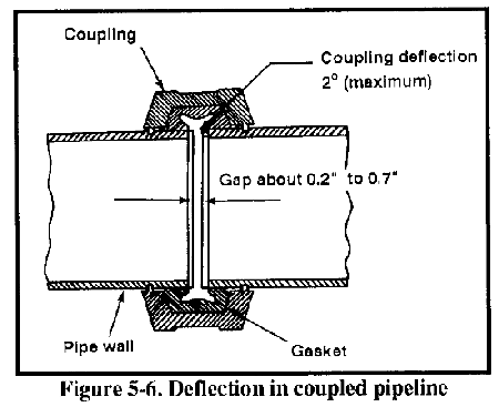
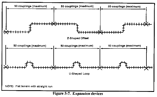
b. Expansion and Contraction of Coupled Pipelines. Surface-laid metallic pipe expands and contracts with changing temperatures. Groove-type couplings provide some angular deflection and slack adjustment between each pipe joint (Figure 5-6). Because aluminum expands and contracts more than steel, control devices (expansion loops) are required to relieve the tension in the pipeline caused by thermal expansion and contraction. Aluminum pipeline is anchored every 1,000 feet, and an expansion device is installed in the center of every 1,000-foot section. The maximum expansion with a differential in temperature of 100 degrees can be as much as 15 inches. The U-loop and Z-loop are two types of expansion devices (Figure 5-7).
- The U-loop is constructed with three 19-foot pipe sections and a combination of 45- or 90-degree elbows.
- The Z-loop is constructed with a 19-foot pipe section offset and 45-degree elbows.
5-3. Hose-Line Systems. The US Armed Forces use hoses extensively in water and petroleum transportation. They can be laid much faster and with less effort than a metallic pipeline. Hose lines do not require extensive cribbing, staking, expansion joints, or other stabilization efforts as metal pipeline systems do. That factor saves time. However, the disadvantages of using hoses are low allowable working pressure, reduced shelf life, and less durability. Because of the low working pressure and the durability problem, hoses usually are used only within TPTs and as a temporary extension or lateral from a rigid pipeline no greater than 5 miles long.
New technologies are addressing the disadvantages of using hose. Durability has been enhanced and working pressures increased so that a hose pipeline is a viable alternative. The OPDS has a MAWP of 740 psi. The shelf life of new hose is currently under investigation. Hoses are connected using either a cam lock or a grooved-type (single or double) coupling clamp. Connecting devices will be discussed later in this chapter.
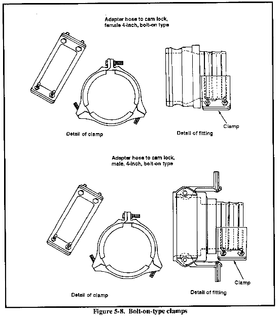
a. 600-Foot, 6-Inch Hose-Reel Assembly. This system is an upgrade to the 250-foot, 6-inch lightweight hose (stored in flaking boxes). The hose-reel system consists of 600 feet of 6-inch lightweight hoses packaged on reels, with two reels mounted on a skid. The MAWP is 150 psi. The hoses do not have attached connecting ends. They will be attached, using a bolt-on-type clamp at assembly time. (Figure 5-8 shows bolt-on-type clamps.) The hose line is manually deployed and has a 24-volt, direct-current, hydraulic power pack for recovery. Six reel systems (two 600-foot reels per system) and one power pack can fit into one ISO container. The reel system eliminates the bending and stressing of the hose and increases the storage life 1 1/2 to 2 times longer than the hoses that are stored in flaking boxes.
b. 4-Mile OPDS. This system, with the SALMS, provides rapid delivery of petroleum from offshore tankers to the shore high-water mark (Figure 5-9). The system, which is constructed by the Navy, uses high-pressure hoses on ship-mounted reels. Each reel holds 0.5 mile of collapsible hoses; eight reels make up the 4-mile kit. Hose-to-hose and hose-to-fitting connections are made with 6- and 12-bolt flange connections that are designed for a burst pressure of 2,200 psi. The 6-inch diameter and 1-inch thick hose has a MAWP of 740 psi. The hose can be stretched to 33 percent under conditions of use. Petroleum is pumped using two positive displacement pumps in parallel (500 GPM each at 700 psi). High pressure is required by the high head losses that result from delivery of 1,000 GPM in the 6-inch hose over the 4-mile (maximum) distance to shore.
c. 50- and 500-Foot, Lightweight, Collapsible, Discharge, 6-Inch Hoses. These hoses have a MAWP of 150 psi. The 500-foot hose is packed two per flaking box and is part of the transfer hose assembly. The 50-foot hose is available individually and is used in the tanker-truck receipt and switching manifolds, tank-farm and fuel-dispensing assemblies, and contaminated-fuel module.
d. 12-Foot, Noncollapsible, Suction, 6-Inch Hose. This hose is used in the tank-farm assembly and tanker-truck receipt manifold.
e. 12-Foot, Noncollapsible, Discharge, 4-Inch Hose. This hose is found in the contaminated fuel module and the 50,000-gallon, TPT, optional-tank configuration.
f. Collapsible, Dispensing, 1-, 1 1/2-, 2-, and 4-Inch Hoses. These hoses are used in the fuel-dispensing assembly and the 50,000-gallon, TPT, optional-tank configuration. The 4-inch hose is available in 25- and 50-foot lengths. The 2-, 1 1/2-, and 1-inch hoses are available in 25-foot lengths.
g. 12-Foot, Suction, 4-Inch Hose Assembly. This hose is used in the tanker-truck receipt manifold; contaminated-fuel module; and the 50,000-gallon, TPT, optional-tank configuration.
5-4. Pipeline and Hose-Line Obstacle Crossing. Points where military pipelines and hose lines cross roads, railroads, watercourses, or any other obstacle require special treatment. When possible, bypass obstacles. If this is not possible, with minimal effort, construct an obstacle-crossing device. It is a good practice to anchor a pipeline at each end of an obstacle crossing and, if the site is susceptible to damage, install a gate valve at each end. Constructing obstacle-crossing sites should take place before pipeline construction reaches that site. This eliminates the need for pup joints and increases the rate of pipeline construction. The most commonly encountered obstacles and ways to negotiate them are discussed below.
NOTE: For discussion purposes, metallic pipelines and hose lines are referred to as pipelines.a. Road and Railroad Crossings. Roads are the most commonly encountered pipeline obstacles. Crossings can be made by running the line through existing culverts. If existing culverts are too far from the pipeline route, install underground culverts using either larger pipe or nestable culvert material. Encase the pipeline in culvert material for protection as well as convenience in installation and maintenance. (When time is a factor, use large diameter pipe or a metal sleeve instead of nestable culvert.) If you use nestable culvert, assemble it in advance and haul it to the job site. When you use an existing culvert, the pipeline will reduce the culvert's cross-sectional area and restrict the water flow. If drainage water contacting the pipeline is a factor, anchor the pipeline so it cannot be swept away. Pipelines crossing culverts require the same amount of cover as a culvert installed for drainage purposes.
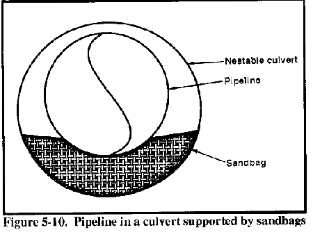
(1) Culvert Size. A culvert 4 inches larger in diameter than the pipeline will provide sufficient clearance for the pipeline. If possible, it with sandbags (Figure 5-10). Anchoring the pipeline at each end of the culvert is best.
(2) Culvert Installation. The opening for the culvert may be made by boring, tunneling, or digging a trench wide enough to receive it. The method used will depend on the type of soil encountered and the available equipment. The most common method is the ditching method. If you use this method, make sure that there is sufficient cover and that it is thoroughly prevent the pipeline from contacting the culvert by supporting compacted.
b. Stream, River, and Ravine Crossing. When possible, use existing structures to cross streams and rivers. If you use an existing bridge, the pipeline will be a more lucrative target. Also, you will have to protect the pipeline from vehicular damage. If an existing structure is unavailable or if the tactical situation is not advisable for pipeline use, construct a crossing device. Do this by either laying the pipeline in a trench at the bottom of the stream or by installing an overhead pipeline that crosses at a site away from (usually downstream) an existing bridge. The method you use will depend on the tactical situation and the conditions that each obstacle presents.
(1) Overhead Crossings. Often a small stream, canal, drainage ditch, or ravine must be crossed above ground when laying coupled pipelines. If the width is too great for an unsupported span (19 and 40 feet for aluminum and steel-coupled pipelines, respectively), you must construct a crossing device. Sometimes, a critical gap structure may be set in the watercourse. If this is not feasible, then the pipeline must be supported by a suspension structure. The critical gap structure and various size suspension-bridge kits are available through AFCS. If the kits are not available, you will have to construct an improvised structure.
(2) Suspension Bridges. Pipeline suspension bridges are prefabricated and packed in kits for 100-, 200-, and 400-foot spans (Figure 5-3). The bridge kits are available through AFCS. Detailed assembly instructions come in the packing list for each kit. Installation procedures for the suspension bridges are as follows:
(a) Choose a crossing site. However, remember that the difference in height between banks must be less than 8 feet. If it is not, you may have to cut one bank with a bulldozer. Do not use a filled area as a tower-base location.
(b) Unpack all assembly parts. Make sure that all the required parts are on hand, and learn to identify them.
(c) Set the tower base in position, using a 20-ton crane, and stake it down.
(d) Assemble the tower by attaching the required fixtures. Erect the tower using a 20-ton crane.
(e) Attach guy wires to the tower assembly and secure them to ground.
(f) Place a 12-inch-diameter pipe deadman on each shore and attach each to a tower assembly.
(g) Attach all cables with U-bolt wire clamps.
(h) Position staging boards to cross bearers.
(i) Attach the tension cable to the cross bearers, parallel with the staging boards.
(j) Attach two wind guys per shore to cross bearers. Secure them to each shore.
(k) Secure 1/4-inch cable with U-bolts to the suspenders.
(l) Construct the pipeline on the bridge from the center to each shore. Position the coupled joints midway between the cross beams. Secure the pipeline to the cross bearers and staging planks with pipe straps.
(m) Use cable turnbuckles to achieve uniform tension on all cables.
(3) Critical Gap Structure. This structure is available through AFCS and is used for crossing small streams and gullies. It is made up of 4-inch-diameter steel tubing, angled steel, and roller assemblies (Figure 5-1). The rollers are installed so the pipeline can move during expansion and contraction. The structure is field-fabricated on-site with welding equipment. Each structure is placed at an interval equal to the length of a stick of pipe, with the coupling positioned directly between the structures.
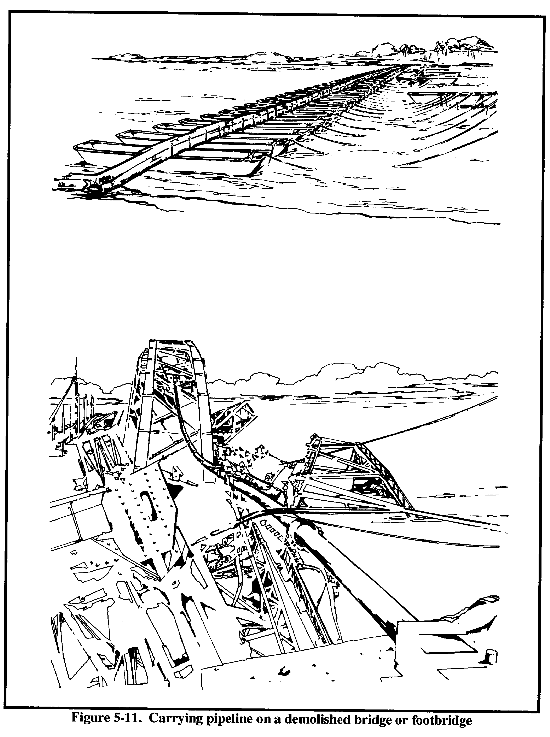
(4) Improvised Structures. Figure 5-2 shows improvised methods of supporting short spans of unsupported pipeline. In emergencies, you can use damaged or demolished bridges or floating footbridges (Figure 5-11) to carry a pipeline. However, construct alternate lines as soon as possible. This is especially true when lines are carried on floating bridges that are unstable and subject to hazards from floods, floating debris, derelict boats, and floating explosive charges placed by enemy partisan forces.
5-5. Pumping Stations. Pumping stations are located along the pipeline trace based on the hydraulic design of the system. They consist of the required pumps and the operating and living facilities for the operating crew. Operating crews are responsible for their own facilities.
The pumping station is made up of a launcher, receiver, and strainer and the pumps connected by pipe. For an aluminum pipeline system, a standard pumping station is made up of two 800-GPM pumps. Pumping stations can be built to any specification. However, they must have the ability to remain operational even when pumps are shut down for maintenance or replacement. Pumping stations are designed to be operational 24 hours per day. A trained engineer squad can construct a standard pumping station (steel or aluminum pipeline system) in one day if given the proper material handling equipment and a prepared pump pad. The material-handling equipment will differ depending on the type and weight of the pumps being installed.
a. Site Selection. Many factors are considered when selecting a site for a pumping station. The site--
- Must be located within the limits of the hydraulic design. If an adjustment is required, it should be towards the source of the fuel, not the demand. This will ensure that sufficient suction pressure is available at the pump.
- Must be in an area that is large enough to set up the station. The number of pumps at the station will determine area size.
- Must be level and strong enough to support the weight of the pumps. Existing facilities such as parking lots and abandoned slabs should be used, if available.
- Should provide access for installing and removing pump units without interfering with piping.
- Should provide for radio communication.
- Should allow any spilled fuel or vapors to drain away from the pumping station and not gather in low pockets in the surrounding area. The station's fuel-supply storage tanks should be located to ensure proper gravity flow to the pumps. Fuel vapor is heavier than air, so vapors settle near the ground and flow downhill. Vapor pools form in low areas unless dispersed by the wind. These vapor pools present fire and explosive hazards.
- Should make use of natural cover and concealment, thereby reducing the amount of artificial camouflage needed if the tactical situation dictates.
- Should have room for the operating crew to set up living and operating facilities. Crew members usually live intents unless structures are available on-site.
b. Pad Construction. The pumping-station pad must be within 5 degrees of level or pumping-unit damage will occur during operation. A level pumping-station pad makes it easier and less time-consuming to assemble the piping that connect the pumps. In a level area, you can predetermine the size and number of pup joints you need and precut these joints. (Precutting pup joints eliminates the need to measure and cut them on-site.)
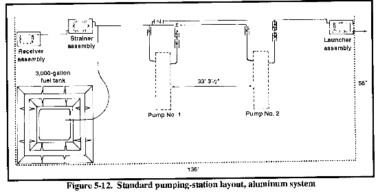
The area required for a standard pumping-station pad is 136 by 58 feet for the aluminum system and 80 by 16 feet for the steel system. The pad can be constructed of concrete or gravel and must support the weight of the pump units. The site should provide access for installing and removing pump units without interfering with piping. A berm is constructed for the fuel-supply storage tanks. Figure 5-12 shows a standard pumping-station layout, aluminum system.
c. Standard Pad Layout. Accurate pumping-station pad layout will ensure that the pump units are positioned so that precut, nonstandard lengths of pipe can be used in assembling the piping between pumps. Assembly time is increased if pup joints are measured and cut on-site. Layout is normally done with stakes and string. Pumps must be situated to allow trucks and material handling equipment ready access without interference with piping and manifold. This enables pumps to be exchanged after the station in built. Pumps are positioned parallel to one another exactly 33 feet 3 1/2 inches apart on center (Figure 5-12).
d. Pump Placement. Pump units should be moved directly from the main issue point to the pumping-station pad. This eliminates unnecessary lifting and loading operations at construction staging areas. A 40-ton, rough-terrain crane and a low-bed trailer are required for loading, moving, and placing each 800-GPM mainline pump unit. When placing pumps, the crane boom will be extended, so the maximum lifting capacity cannot be used.
e. Pumping-Station Construction Checklist. Consider the following when constructing a mainline pumping station:
- Pad construction, completed.
- Pump-pad layout, completed.
- Pup joints, precut.
- Pumps, positioned on pad. All transportation and lifting support scheduled for mainline pumps, shelters, receiver, launcher, and strainer.
- Pumping units, reprocessed. Pump units that are received from war stocks or that are new must be reprocessed before operating them. This includes installing and aligning the engine to the pump coupler, filling all fluid reservoirs, running the engine for break-in period, and calibrating all gauges. The operator's manual for the 800-GPM mainline pump is TM 5-4320-307-10.
- Suction and discharge manifolds on each pump, installed. These are steel and are bolted to a flange on the pump unit.
- Pipe and valves connecting pumps, installed. After pump units are positioned, the suction and discharge manifolds are installed on each pump.
- Strainer, launcher, and receiver, placed and connected, These items are placed with the 7 l/2-ton crane and connected to the system.
- Auxiliary fuel source, placed and connected. The 3,000-gallon fabric tank and liner is installed with a berm around it.
5-6. Testing Pipeline Systems.
a. Responsibility. The commanding officer of the unit that constructed any given segment of the pipeline is responsible for coordinating the testing and inspection of his unit's work. The constructing and operating units conduct the testing and inspection. Turnover will take place when the certificate of operability is signed. If inspection and test results are not within established standards, the commander of the operating unit may reject the line as unsuitable for operation.
b. Certificate of Operability. After the pipeline is tested, inspected, and found to be constructed to standard, the operating unit prepares an operability certificate and forwards it to the constructing unit and higher headquarters. The commanding officers of the constructing and operating units sign the certificate. The certificate contains--
- A statement as to the operability of the line and its acceptance by the operating unit.
- The section and mileage of the line tested.
- The standard to which the line was built and tested.
- The testing pressure.
- The test method and duration of the test.
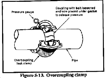
c. Measuring Pressure. To test a section of pipeline, place a pressure gauge at each end of the section. The test-section ends are normally at the pumping-stations. With the aluminum pipeline system, mount a pressure gauge on the launcher and receiver assemblies, which are used as the ends of the test section. In the steel pipeline system, mount a pressure gauge in the vent-plug tap of an overcoupling clamp (Figure 5-13). To install the clamp and gauge device in the steel system, loosen the coupling at a joint and remove the gasket to cause a temporary leak. Retighten the bolts on the coupling and fasten the clamp and gauge device over the coupling.
d. Hydrostatic Testing (Fill and Test). Military pipelines may be tested in long or short sections with water (and under special circumstances with fuel) using the pumping stations to develop the necessary pressure.
(1) Using Fresh Water. Because of safety and economy, fresh water is preferred. The water should be as clean as possible, but it does not have to be potable. If the water is very muddy, pump it into a temporary impounding basin and let the silt settle out. You may have to construct a temporary pipeline or hose line from the water source to the pipeline. Also, if the flow rate at the source is not sufficient, you may have to construct an impounding basin so that sufficient water can be collected in advance. Fresh water may be too difficult to obtain in sufficient quantity in tidewater areas. If possible, pump freshwater from an inland source backwards through the pipeline to the marine terminal area by making a temporary change in the pumping station's piping system.
(2) Using Salt Water. If you do not have sufficient quantities of fresh water, you may use salt water. Once you complete the fill-and-test procedures, flush the line several times with clean fresh water, if possible, separated by pipeline cleaners, before packing or filling the line with fuel. Salt water will--
- Not adversely affect the fuel any more than dirty freshwater.
- Ultimately be removed by filter/separators at dispensing stations.
- Not cause significant corrosion inside the steel pipe, when used only once in testing.
- Be removed by the pipeline cleaners used in flushing the pipeline and initially packing the line with fuel.
The inside surfaces of steel-tubing sections from military storage depots will normally be corroded and contain some dirt. Swabbing the sections once during pipeline construction will only remove sticks, dirt clods, stones, scaly rust, reptiles, and so forth. Proper cleaning requires swabbing the pipeline several times. It also ensures the removal of all air from the pipeline. Do not use fresh water to test the pipeline in prolonged subfreezing temperature or if you cannot remove the water using pipeline cleaners. Pack the line with fuel before subfreezing weather. If you use ocean salt water (freezing point about 27.5° F), you can test the line at a lower temperature than if you use fresh water. If necessary, add salt or calcium chloride to the water to lower its freezing point.
(3) Using Fuel. Testing with salt water is preferable to testing with fuel. Test with fuel only as a last resort in an extreme emergency, when no water is available or when extremely cold climatic conditions make hydrostatic testing with fresh water or salt water impractical. If you must use fuel, use diesel (or jet) fuel, since it is less volatile and less toxic than leaded gasoline. Testing with fuel will normally delay completion and operation of the pipeline, even if you take proper safety precautions.
When using fuel, tank trucks and fire-fighting equipment must be available for draining the line sections that leak. Make sure you have plenty of overleak couplings to temporarily correct small leaks. Before testing, install a T and a valve at the bottom of long slopes, as a temporary measure. Doing so will make draining the line easier and allow you to attach a hose line or pipeline to tank trucks to receive the fuel.
Do not let the fuel drain onto the ground or into roadside ditches or streams. To do so not only creates a serious safety hazard but also results in air, water, and ground pollution and can result in vegetation, livestock, wildlife, water-fowl, and marine-life destruction. The US Government could be financially responsible for such damages. Because testing a pipeline with fuel presents many hazards, the noncommissioned officer in charge (NCOIC) or officer in charge (OIC) should try to get written orders before proceeding with such tests. If you have to drain fuel at a point where a T is not installed, do the following:
- Dig a pit large enough to contain all the fuel.
- Construct dikes, if necessary.
- Line the pit with a tarpaulin to minimize contaminating the fuel and the ground by each other, if possible.
- Anchor the line securely on both sides of the coupling you are to remove.
- Have spare piping sections available in case the coupling suddenly slips out of the grooves and damages them as you loosen the nuts. Be careful because loosening a coupling at the bottom of a long slope that may be under a large hydrostatic head is dangerous. The two ends of the line may whip about and create sparks. Fuel may spray several feet in an unpredictable direction. Spraying liquid under several hundred pounds of pressure can seriously injure the eyes.
- Make sure that fire-fighting equipment is readily available.
- Make sure that an explosive-vapor detection meter is available.
- Have a pneumatic sump pump and tank truck standing by to recover fuel.
- Test pumping-station manifolds to ensure that no leaks will occur because of inherent hazards present at pumping stations. Such hazards could be hot exhaust stacks, sparking generator brushes, electric light bulbs and electric generators, violators of No Smoking regulations, and passing vehicles.
(4) Criteria.
(a) Communication. There must be reliable communication at the start point of the pipeline, between the pumping stations, and at the end of the test section. All pumping stations must be able to communicate with the fuel dispatcher, who controls the entire system and may be hundreds of miles away. Long-range amplitude modulation radios must be at each pumping station before starting fill-and-test procedures. Also, the quartermaster branch pipeline operating units must have these radios for operating the pipeline. Pipeline operating units have the required AM radios in their modification table of organization and equipment (MTOE). Crews that examine the pipeline test section must have communications among themselves. Short-range frequency modulation radio sets, within the constructing unit's MTOE, are used between the test-section inspection crews.
(b) Calibration. All pressure gauges must be calibrated before testing. A deadweight tester is used for this purpose.
(c) Inspection. The inspecting crew members must be dependable and have good sight and hearing. Double checking and strict supervision of the inspecting crew are essential. An undetected leak may require shutting down the line for many hours and spending thousands of man-hours and equipment hours repairing and repacking the line with fuel. Mark leaks so that they can be identified for future repair. Inspecting crews should categorize leaks and measure the loss as accurately as possible, such as the number of drops per minute.
(5) Procedures.
(a) Inspect the pipeline test section to ensure that all vent and gate valves are open. Vent valves are located on hilltops and opened to drain air from the pipeline system. Gate valves must be completely open or they will restrict the passage of the line scraper.
(b) Begin pumping the test medium from the pumping station at a rate of 300 GPM. Maintain this rate by opening or closing the discharge valve on the pump unit. A crew will walk with the scraper, monitoring its exact location.
(c) Insert a line scraper to ensure that all air and any debris are pushed out of the line, after pumping about 3,000 gallons. Crew members (also called pig walkers) will close the vent valve as the scraper passes the valve and a steady stream of test medium is flowing. They will monitor the exact location of the scraper and maintain radio contact with the dispatcher at the closest pumping station. If fuel is used as a test medium, a collection plan must be followed to capture the fuel.
(d) Isolate the line by slowly closing the launcher, receiver, or gate valve as soon as the scraper reaches the end of the test section. Open the initiating pump-unit vent valve, slightly, at the pumping station producing the pressure or the gate valve at the end of the test section. This will prevent the pump from overheating and will not affect attaining the test pressures. The pumping-station operator can easily detect the proper flow rate to prevent overheating by placing one hand on the pump casing and the other on the inlet pipe. There should be no significant difference in temperature.
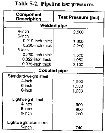
(e) Increase the discharge pressure of the initiating pump to the desired test pressure (Table 5-2), normally using 50-psi increments. It takes about 2 to 3 minutes for each 50-psi increase. Coordinate this throttling process by telephone or radio with the dispatcher. As pressure is increased at the initiating pumping station, it should also increase at the end of the test-section pressure gauge. If this pressure increase does not occur, there is either a major leak or an obstruction in the line. Shut down the line immediately and inspect it.
(f) Close off the test section at the initiating pumping station using the launcher assembly or a gate valve as soon as pressure has built up. Immediately decrease the discharge pressure of the initiating pump and take it off-line.
(g) Inspect the test section and mark leaks. Leaks are detected by sight or by feel. Slight leaks can often be eliminated by shaking the joint. To do this, place a pick handle, crowbar, or similar lever under the coupling and lift the coupling quickly several times. If you cannot correct small leaks at couplings, mark the couplings and estimate the quantity of the leak. If a large leak occurs, shut down the pumping station, temporarily install an overleak clamp, and resume testing. Locate all leaks before emptying the line to make repairs. While the leaks are being marked, the line pressure is monitored at each end.
(h) Repair and retest the line until it meets the standards established by higher headquarters. If you cannot drain the line before repairing, isolate the area to be repaired by closing the nearest gate valve in each direction. If fuel has been used as a test medium, drain the fuel into a suitable container before starting any repairs. Make sure that the line is not under pressure during repair. Repair all leaks by replacing the defective pipe section, coupling, and gasket. Continue testing the entire pipeline.
| DANGER
Removing a coupling on a high-pressure line could result in severe injury or death. |
e. Compressed-Air Testing. Do not use compressed-air testing for high-pressure overland pipelines. A line failure under a high-pressure air test would be an explosive failure since the compressed air within the pipe would be rapidly released. Liquids are incompressible and are, therefore, safer test media.
Air testing will produce many leaks that will not occur with water or fuel testing. Water or fuel may dissolve and wash away small pieces of dirt underneath a gasket, which will then seal; air will not. Many gaskets, especially old ones, will not seat or seal initially under low pressure. With air testing, you will have to perform an initial cleaning and flushing of the line with water and pipeline cleaners to remove residual dirt and rust before the line is packed with fuel. Otherwise, a large amount of fuel will be contaminated, and an unnecessary load will be placed on the sand traps and filter/separators to decontaminate the fuel.
Although hydrostatic testing of sections of welded pipelines for tanker unloading during the onshore construction phase is best, air testing is relatively safe and reliable. Submarine pipelines are weight-coated (to make them heavy enough to remain on the bottom) and therefore are not likely to whip about even if a welded joint should fail suddenly and completely. Also, 110-psi air pressure is equal to or slightly greater than the normal pressure of 100 to 110 psi that tanker captains will allow on their pumps.
Using soapy water to detect leaking couplings is tedious, time-consuming, and difficult. You must apply soapy water to both sides of the coupling and to the two joints between their ends and watch for leaks. To do this, you have to lift each joint about 1 foot or more off the ground so you can apply the soapy water to the underside of the coupling and watch for air bubbles.
f. Locating Obstructions in a Pipeline. If the pipeline has been properly and carefully constructed, no obstructions should remain. However, when tests show a pressure drop at the far end of the test section or an increase in pressure at the initiating pump, an obstruction is probably present. The easiest way to locate the obstruction is to use a scraper. Insert the line scraper upstream from the obstruction. A walking patrol will follow the scraper until it stops. The line is then shut down and the obstruction removed.
|
NEWSLETTER
|
| Join the GlobalSecurity.org mailing list |
|
|
|


