

 [ Navy Training System Plans ]
APPROVED
NAVY TRAINING SYSTEM PLAN
FOR THE
TS-3846A/ASM-608(V) INERTIAL
MEASUREMENT UNIT TEST SET III
N88-NTSP-A-50-8116B/A
MARCH 2000
EXECUTIVE SUMMARY
The TS-3846A/ASM-608(V) Inertial Measurement Unit Test Set (IMUTS) III was first introduced to the fleet in March 1997 onboard the USS Nimitz (CVN-68). To date, 91 IMUTS III systems have been installed at various United States Navy Aircraft Intermediate Maintenance Departments (AIMDs) both ashore and afloat and United States Marine Corps Marine Aviation Logistics Squadrons (MALSs). IMUTS III was introduced into the fleet through retrofit of the IMUTS II equipment. Engineering Change Proposal 92-002 updated IMUTS II benches into IMUTS III benches. In the remainder of Fiscal Year 00, the final five IMUTS III units will be installed. The IMUTS III system is in Phase III (Production, Deployment, and Operational Support) of the acquisition process.
IMUTS III system manpower requirements are based on three working shifts for AIMDs ashore, and two working shifts for AIMDs afloat and MALS. The IMUTS III system is operated and maintained by Navy Aviation Electrician's Mate personnel with Navy Enlisted Classification 7197, and Marine Corps personnel with Military Occupational Specialty 6464. No increase in manpower was required with the introduction of the IMUTS III.
IMUTS III follow-on training became available in July 1997 at Maintenance Training Unit (MTU) 3010, Naval Air Station Oceana, Virginia, and at MTU 3011, Marine Corps Air Station Miramar, California.
Page
Executive Summary i
List of Acronyms iii
Preface vii
PART I - TECHNICAL PROGRAM DATA
A. Nomenclature-Title-Program I-1
B. Security Classification I-1
C. Manpower, Personnel, and Training Principals I-1
D. System Description I-2
E. Developmental Test and Operational Test I-2
F. Aircraft and/or Equipment/System/Subsystem Replaced I-2
G. Description of New Development I-2
H. Concepts I-6
I. Onboard (In-Service) Training I-9
J. Logistics Support I-11
K. Schedules I-12
L. Government-Furnished Equipment and Contractor-Furnished Equipment Training Requirements I-15
M. Related NTSPs and Other Applicable Documents I-15
PART II - BILLET AND PERSONNEL REQUIREMENTS II-1
PART III - TRAINING REQUIREMENTS III-1
PART IV - TRAINING LOGISTICS SUPPORT REQUIREMENTS IV-1
PART V - MPT MILESTONES V-1
PART VI - DECISION ITEMS/ACTION REQUIRED VI-1
PART VII - POINTS OF CONTACT VII-1
AC |
Alternating Current |
ACDU |
Active Duty |
A/D |
Analog to Digital |
AE |
Aviation Electrician's Mate |
AFB |
Air Force Base |
AIMD |
Aircraft Intermediate Maintenance Department |
AMTCS |
Aviation Maintenance Training Continuum System |
CAINS |
Carrier Aircraft Inertial Navigation System |
CBT |
Computer-Based Training |
CD-ROM |
Compact Disc-Read Only Memory |
CETS |
Contractor Engineering Technical Services |
CFE |
Contractor Furnished Equipment |
CIN |
Course Identification Number |
CINCLANTFLT |
Commander In Chief Atlantic Fleet |
CINCPACFLT |
Commander In Chief Pacific Fleet |
CMC |
Commandant of the Marine Corps |
CNET |
Chief of Naval Education and Training |
CNO |
Chief of Naval Operations |
COMNAVAIRESFOR |
Commander Naval Air Reserve Forces |
COMNAVRESFOR |
Commander Naval Reserve Forces |
CPU |
Central Processing Unit |
CV |
Aircraft Carrier |
CVN |
Aircraft Carrier, Nuclear |
DC |
Direct Current |
ECP |
Engineering Change Proposal |
EVSA |
Equipment Verification Standard Assembly |
FMS |
Foreign Military Sales |
FY |
Fiscal Year |
GPIB |
General Purpose Interface Bus |
Hz |
Hertz |
ID |
Interface Device |
ILSP |
Integrated Logistics Support Plan |
IMA |
Intermediate Maintenance Activity |
IMU |
Inertial Measurement Unit |
IMUTS |
Inertial Measurement Unit Test Set |
INU |
Inertial Navigation Unit |
IPB |
Illustrated Parts Breakdown |
JRB |
Joint Reserve Base |
MALS |
Marine Aviation Logistic Squadron |
MAM |
Maintenance Assist Module |
MATMEP |
Maintenance Training Management and Evaluation Program |
MB |
Megabyte |
MCAS |
Marine Corps Air Station |
MF |
Mobile Facility |
MOS |
Military Occupational Specialty |
MRC |
Maintenance Requirement Cards |
MSD |
Material Support Date |
MTBF |
Mean Time Between Failures |
MTIP |
Maintenance Training Improvement Program |
MTPSI |
Master Test Program Set Index |
MTU |
Maintenance Training Unit |
NA |
Not Applicable |
NADEP |
Naval Aviation Depot |
NAMP |
Naval Aviation Maintenance Program |
NAMTG |
Naval Air Maintenance Training Group |
NAMTRAGRU DET |
Naval Air Maintenance Training Group Detachment |
NAS |
Naval Air Station |
NATEC |
Naval Air Technical Data and Engineering Service Command |
NAVAIR |
Naval Air |
NAVAIRSYSCOM |
Naval Air Systems Command |
NAVPERSCOM |
Naval Personnel Command |
NEC |
Navy Enlisted Classification |
NETS |
Navy Engineering Technical Services |
NTSP |
Navy Training System Plan |
OPNAV |
Office of the Chief of Naval Operations |
OPNAVINST |
Office of the Chief of Naval Operations Instruction |
OPO |
OPNAV Principal Official |
PCU |
Power Component Unit |
PDA |
Principal Development Activity |
PMA |
Program Manager, Air |
P/N |
Part Number |
PSICP |
Program Support Inventory Control Point |
RAIMD |
Reserve Aircraft Intermediate Maintenance Department |
RFT |
Ready For Training |
SEC |
Support Equipment Change |
SELRES |
Selected Reserve |
SINS |
Ship's Inertial Navigation System |
SRA |
Shop Replaceable Assembly |
SVGA |
Super Video Graphics Array |
TAR |
Training and Administration of the Naval Reserve |
TD |
Training Device |
TFS |
Total Force Structure |
TMMT |
Technical Manual Management Team |
TPS |
Test Program Set |
TSA |
Training Support Activity |
TSM |
Test Station Medium |
TSMB |
Test Set Module Block |
TTE |
Technical Training Equipment |
ULSS |
User's Logistics Support Summary |
USMC |
United States Marine Corps |
USN |
United States Navy |
USS |
United States Ship |
UUT |
Unit Under Test |
VAC |
Volts Alternating Current |
VDC |
Volts Direct Current |
WRA |
Weapon Replaceable Assembly |
ZIF |
Zero Insertion Force |
PREFACE
This Approved Navy Training System Plan (NTSP) for the Inertial Measurement Unit Test Set (IMUTS) III has been updated to comply with guidelines set forth in the Navy Training Requirements Documentation Manual, OPNAV Publication P-751-1-9-97. This NTSP is an update to the Draft Navy Training System Plan N88-NTSP A-50-8116B/D dated August 1999.
The transition from IMUTS II to IMUTS III is almost complete. All current IMUTS III information, including manpower, training, training support equipment, schedules, and points of contact, are included in this NTSP.
N88-NTSP-A-50-8116B/A
March 2000
PART I - TECHNICAL PROGRAM DATA
A. NOMENCLATURE-TITLE-PROGRAM
1. Nomenclature-Title-Acronym. TS-3846A/ASM-608(V), Inertial Measurement Unit Test Set (IMUTS) III
2. Program Element. 24161N
B. SECURITY CLASSIFICATION
1. System Characteristics Unclassified
2. Capabilities Unclassified
3. Functions Unclassified
C. MANPOWER, PERSONNEL, AND TRAINING PRINCIPALS
OPNAV Principal Official (OPO) Program Sponsor CNO (N885)
OPO Resource Sponsor CNO (N885)
Developing Agency NAVAIRSYSCOM (PMA260)
Training Agency CINCLANTFLT
CINCPACFLT
CNET
COMNAVRESFOR
Training Support Agency NAVAIRSYSCOM (PMA205)
COMNAVAIRESFOR
Manpower and Personnel Mission Sponsor CNO (N12)
NAVPERSCOM (PERS-4, PERS-404)
Director of Naval Training CNO (N7)
Marine Corps Combat Development Command
Manpower Management TFS Division
D. SYSTEM DESCRIPTION
1. Operational Uses. The TS-3846A/ASM-608(V) IMUTS III, from here on to be referred to as the IMUTS system, has the capability to self-check and to test and diagnose Carrier Aircraft Inertial Navigation System (CAINS) and CAINS II Weapon Replaceable Assemblies (WRAs). These WRAs include the CAINS Inertial Measurement Unit (IMU) CN-1263/ASN-92(V), CAINS IA Inertial Navigation Unit (INU) CN-1561/ASN-130A, and the CAINS II INU CN-1649 ASN-139 in support of the following aircraft: A-6E, AV-8B, E-2C, EA-6B, ES-3A, F-14A/B/D, F/A-18A/B/C/D/E/F, and the S-3A/B. The IMUTS system is positioned at Aircraft Intermediate Maintenance Departments (AIMDs), Naval Aviation Depots (NADEPs), Mobile Facility (MF) vans, Foreign Military Sales (FMS) sites, Marine Aviation Logistics Squadrons (MALS), and selected contractor facilities.
2. Foreign Military Sales. The IMUTS system is a candidate for FMS and has already been provided to some of our allies. For information on FMS refer to Program Manager, Air (PMA) 260.
E. DEVELOPMENTAL TEST AND OPERATIONAL TEST. Developmental Testing for the IMUTS system was successfully completed in Fiscal Year (FY)96. No Operational Test was required.
F. AIRCRAFT AND/OR EQUIPMENT/SYSTEM/SUBSYSTEM REPLACED. Engineering Change Proposal (ECP) #92-002 modifies the IMUTS system, upgrading it from IMUTS II Part Number (P/N) 262200-2 to IMUTS III P/N 262200-3. Support Equipment Change (SEC) 5258 is the Technical Directive to implement the modification.
G. DESCRIPTION OF NEW DEVELOPMENT
1. Functional Description. The basic IMUTS system has the capability to self-check and to test and diagnose WRAs to their faulty Shop Replaceable Assemblies (SRAs). The IMUTS system operation and program execution is under control of the computer assembly installed in the IMUTS system. The Unit Under Test (UUT) application programs are stored on hard disk and executed in the computer. Test instructions are transmitted from the computer to the various modules in the IMUTS system via the computer bus network. Responses from test instructions are transmitted back to the computer via the same bus network. The computer executes interface control commands and selects the Test Station Modules (TSMs) required to apply test stimuli and process UUT response data. TSMs interface with the computer assembly via the computer bus. The UUT is mounted on a holding fixture on the IMUTS system and tested via the associated Interface Device (ID). The operator control interface with the computer is provided by means of a Super Video Graphics Array (SVGA) monitor, keyboard, and printer. The major IMUTS system assemblies are the Console, Holding Fixture, and Hex Extenders. The Console consists of the following (see Figure I-1):
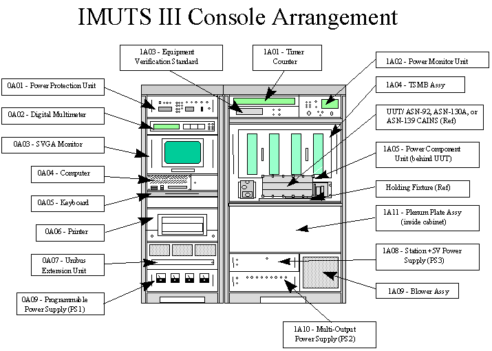
Figure I-1.
a. Digital Multimeter Assembly. The programmable Digital Multimeter provides a continuous readout of Direct Current (DC), Alternating Current (AC), and resistance measurements. In the automatic mode of operation, the multimeter is controlled by the computer via the bus. Information is put on the bus by the multimeter for comparison to required values by the computer. In the manual mode of operation, the station maintenance technician may use the multimeter to assist in diagnosing problems with the IMUTS system.
b. Unibus Extension Unit. The Unibus Extension Unit communicates with the computer assembly, houses the Unibus Adapter Module, Output Controller, Bus Buffer Interface, and the Ship's Inertial Navigation System (SINS) Interface.
c. Timer/Counter. The Timer/Counter provides universal counter measurement modes, computation capabilities, keyboard entry, 9-digit display, annunciators, and manual and automatic trigger level settings.
d. Programmable Power Supply. This Astro-Geo-Marine Power Supply consists of two sections and provides 0 to +40 Volts Direct Current (VDC), 15 amperes, and 0 to -40 VDC, 5 amperes.
e. Station +5VDC Power Supply. This Astro-Geo-Marine Power Supply provides a regulated 5 VDC output with a full load rating of 100 amperes to operate certain functions of the Test Set Module Block (TSMB) Assembly. Current limiting and overvoltage circuitry protect the power supply from electrical irregularities. The power supply contains two heat sinks: a transistor heat sink and a diode heat sink. Thermal detectors in each heat sink open at 100 degrees Celsius and shut down the power supply in the event of overheat conditions. Normal cooling is provided by one fan contained within the power supply.
f. Multi-Output Power Supply. This Astro-Geo-Marine DC Power Supply consists of six sections and provides ± 15 VDC at 4 amperes, ± 35 VDC at 6 amperes, ± 10 VDC at 1 ampere, ± 20VDC at 1 ampere, and ± 28 VDC at 10 amperes. Current limiting and overvoltage circuitry protects the power supply from excess current drain or overvoltage conditions. Thermal switches sense any overtemperature conditions and shut down the power supply. Two fans that operate from the line voltage provide cooling.
g. Super Video Graphics Array. The SVGA Monitor displays information called up or composed by the keyboard and the results of software controlled tests. The kind of information called up will be the discrete program steps of the test programs. Should a fault be detected within the UUT, this will be displayed together with recommended corrective measures.
h. Keyboard. The Keyboard allows the operator to communicate with the computer.
i. Printer. The Okidata OL600e is a laser quality printer with 300 dots per inch resolution, 6 pages per minute speed, and a standard bi-directional parallel port Centronics cable. It has 100 sheet input capability, a toner cartridge life of 2,000 pages, and an image drum life of 20,000 pages. There are 35 Intellifont and 10 True Type Scaleable Fonts, plus a United States Postal Service Postnet Barcode Font. All operations are available from the front of the unit such as inputting paper, retrieving output paper, and removing and installing cartridges and drums.
j. Power Protection Unit. The Power Protection Unit (PPU) contains a 115 VAC (Volts Alternating Current) to 24 VAC step-down transformer, two voltage surge protectors, four voltage sensors, and three contained relays in a slide-mounted chassis. Circuit breakers, control switches, and indicator lights are mounted on the front panel of the chassis, while connectors and one switch are mounted on the rear panel.
k. Power Monitor Unit. The Power Monitor Unit (PMU) monitors the magnitude of 400 and 60 Hertz (Hz) voltage and frequency supplied to the IMUTS system. Provisions are made for displaying these parameters on a front panel "Voltage and Frequency" meter. The operator may select the input to be read using the "Display Select" rotary switch. The 400Hz incoming voltage and frequency are monitored for proper phase rotation and if the proper rotation is present, the "Phase Sequence Correct" indicator will be illuminated.
l. Equipment Verification Standard Assembly. The Equipment Verification Standard Assembly (EVSA) permits the IMUTS system operator to make precision on-site verification of the accuracy of the counter and the multimeter while installed in the IMUTS system, resulting in no need to periodically remove the items for calibration. The EVSA provides precision outputs to the counter and multimeter via hardware. The outputs to be generated are selected via the front panel controls. The accuracy of the counter and multimeter are determined by the accuracy with which precision inputs are read.
m. Power Component Unit. The Power Component Unit (PCU) provides 115 VAC, 400 Hz, 3-phase, ± 28 VDC programmable power and 26 VAC reference phase power to the UUT. The PCU also provides 115 VAC, 400 Hz, A-phase power to the console assembly air valve. Additionally, the PCU monitors power to the UUT and status compared via the Analog-to Digital (A/D) converter in the processor unit. Front panel test points are provided for monitoring the IMUTS system AC and DC voltages.
n. Computer Assembly. The Computer Assembly contains a passive back plane with a mounted Central Processing Unit (CPU) Module which contains a 16 Megabyte (MB) Random Access Memory (RAM), Video Module, Unibus Controller Module, A/D Converter, 1553 Interface Module, Institute of Electrical and Electronics Engineers (IEEE) 488 Interface Module/General Purpose Interface Bus (GPIB), Simple Computer System Interface (SCSI)/ Compact Disc-Read Only Memory (CD-ROM) Controller Module, 3.5-inch MB Floppy Drive, Hard Drive, Four-Speed CD-ROM Drive, 400 Watt Power Supply, Computer Chassis, Monitor Power Cable, and a Computer Power Cable.
o. Test Set Module Block Assembly. The TSMB Assembly develops UUT stimuli under computer control and monitors UUT responses. The UUT requires and outputs both analog and digital data while the computer provides and recognizes only digital data. The TSMB Assembly is primarily a relay switching network and signal conditioning system to permit proper communication between the computer and the UUT. The TSMB Assembly contains the Zero Insertion Force (ZIF) connector.
p. Plenum Plate Assembly. The Plenum Plate Assembly directs cooling air from the Blower Assembly to the UUT.
q. Blower Assembly. The Blower Assembly provides air to the UUT and the Console Assembly.
r. Holding Fixture Assembly. The Holding Fixture Assembly is affixed to the IMUTS system work surface assembly to attach the UUTs in a manner consistent with that specified in MIL-N-81604. The fixture provides a surface stable in all axes to ± 1.0 arc-minute relative to the surface to which the test fixture is affixed. At installation time, the work surface to which the fixture is affixed must be leveled to within one degree with respect to local vertical. Each UUT ID is provided with mechanical locking devices relative to the work surface such that the device remains fixed in place after ZIF mating has occurred.
s. Hex Extenders. The Hex Extenders are used to extend cards in the TSMB or Unibus Unit for the purpose of troubleshooting during station maintenance.
2. Physical Description. The IMUTS system consists of a console assembly with the following dimensions:
Height 76 inches
Depth 43 inches
Width 59 inches
Weight 1,560 pounds
Floor load 200 pounds per square foot (maximum)
3. New Development Introduction. The IMUTS system was introduced through retrofit of the IMUTS II. The IMUTS II was updated via ECP 92-002 and SEC 5258. Upon completion of the ECP the unit was designated the IMUTS III system.
4. Significant Interfaces. The IMUTS system interfaces with the SINS. Interfaces for the IMUTS system remain the same as for the IMUTS II. There are no new interface requirements for the IMUTS system.
5. New Features, Configurations, or Material. The IMUTS system requires a Floppy Disk of Start-up Software (P/N DS262200-802) and a Software Kit (CD262200-402) which contains a CD-ROM of software. Revised Software Kit (CD262200-403) is scheduled for release in November 1999.
H. CONCEPTS
1. Operational Concept. The daily usage for the IMUTS system is 20 hours per day. The expected service life is 30 years. The maintenance cycle is 2,400 hours and the Mean Time Between Failures (MTBF) is 450 hours. The IMUTS system is operated by United States Navy (USN) Aviation Electrician's Mate (AE) personnel with Navy Enlisted Classification (NEC) 7197, and United States Marine Corps (USMC) personnel with Military Occupational Specialty (MOS) 6464. The IMUTS system is not used at the organizational level of maintenance.
2. Maintenance Concept. The Naval Aviation Maintenance Program (NAMP), OPNAVINST 4790.2 series, provides general direction and guidance concerning the maintenance concept for the IMUTS system. The NAMP prescribes three levels of maintenance: organizational, intermediate, and depot.
a. Organizational. Not Applicable (NA)
b. Intermediate. Intermediate level maintenance personnel consist of USN AE personnel with NEC 7197 and USMC personnel with MOS 6464. Intermediate level maintenance personnel perform both Preventive and Corrective Maintenance as listed below.
(1) Preventive. Intermediate level maintenance personnel perform Preventive Maintenance per Part III of the IMUTS system Maintenance Plan (M70097037) and appropriate maintenance manuals and Maintenance Requirement Cards (MRCs). Site calibration personnel calibrate items assigned as intermediate level responsibility per NAVAIR 17-35MTL-2. Preventive Maintenance consists of cleaning and inspecting all vents and air filters, cleaning and lubricating, and performing a self-check program which is run daily or when the IMUTS system is started after a down period.
(2) Corrective. Intermediate level maintenance personnel fault-isolate the IMUTS system to a major assembly and repair the IMUTS system by repair or replacement of major assemblies. Fault-isolation is accomplished using Maintenance Assist Modules (MAMs), Hex Extenders, self-test or self-check program, and additional support equipment. Corrosion Control is performed per NAVAIR 16-1-540 and any physical damage is repaired. Corrective Maintenance consists of using both self-test and diagnostic program disks to fault-isolate to the SRA level.
c. Depot. Depot level personnel perform both Preventive and Corrective Maintenance as listed below.
(1) Preventive. Depot level personnel calibrate the IMUTS system as specified in NAVAIR 17-35MTL-1.
(2) Corrective. NADEP North Island personnel repair or condemn items beyond the capability of maintenance at the intermediate level or items Source, Maintenance, and Recoverability (SM&R) coded for depot repair only.
d. Interim Maintenance. Interim maintenance was not required for the IMUTS system as there was sufficient training provided by the installation team and that was deemed sufficient for the IMUTS system technicians.
e. Life-Cycle Maintenance Plan. There is no Life Cycle Maintenance Plan for the IMUTS system. In the event of a major problem, a Depot Field Repair Team including Litton representatives will complete on-site repair.
3. Manning Concept. The IMUTS system manpower requirements are based on three working shifts for AIMDs ashore, two working shifts for AIMDs afloat and MALSs. The IMUTS system is operated and maintained by USN personnel with NEC 7197, ASM-608 Inertial Measurement Unit Test Set Maintenance Technician, and USMC personnel with MOS 6464, Aircraft Inertial Navigation System Technician, Intermediate Maintenance Activity (IMA).
4. Training Concept. The goal of the IMUTS system training concept is to provide qualified intermediate level USN AEs with NEC 7197 to AIMDs ashore and afloat, and to provide qualified USMC personnel with MOS 6464 to MALSs in the United States and overseas. Training is provided by Maintenance Training Units (MTUs) 3010 and 3011 at Naval Air Station (NAS) Oceana and Marine Corps Air Station (MCAS) Miramar, respectively. Each MTU has two complete IMUTS systems used for Technical Training Equipment (TTE).
For reserve program units, Training and Administration of the Naval Reserve (TAR) personnel receive their training through attending the MTU training, while Selected Reserve (SELRES) personnel may earn intermediate level maintenance qualifications by attending formal training at the MTUs, providing quotas, funding, and students are available to attend the training. Specific guidelines are contained in NAVPERS 18068F Volume II, Chapter IV, Navy Enlisted Classifications.
The established training concept for most aviation maintenance training divides "A" School courses into two or more segments called Core and Strand. The "C" School courses are also divided into separate Initial and Career training courses which are not required for intermediate level training at this time. "A" School Core courses include general knowledge and skills training for the particular rating, while "A" School Strand courses focus on the more specialized training requirements for that rating and a specific aircraft or equipment, based on the student's fleet activity destination. Strand training immediately follows Core training and is part of the "A" School. Upon completion of Core and Strand "A" School, graduates attend the appropriate "C" School for additional specific training. "C" School training is provided for personnel to enhance skills and knowledge within their field.
a. Initial Training. Initial Training for the IMUTS system was completed in FY97. No additional Initial Training is required.
b. Follow-on Training. Follow-on training is provided by MTU 3010, Naval Air Maintenance Training Group Detachment (NAMTRAGRU DET) NAS Oceana for personnel assigned to the east coast and by MTU 3011 NAMTRAGRU DET MCAS Miramar for personnel assigned to the west coast. MTU 3010 and 3011 provide training for both USN and USMC personnel. Training is currently on-line at both MTU 3010 and 3011. In January 1999, the course length of C-198-3060, AN/ASM-608(V) Inertial Measurement Unit Test Set Operator/Maintainer Intermediate Maintenance, was reduced from 47 days to 40 days. C-198-3060 is the heart of training track D/E-150-6010, AN/ASM-608(V) Inertial Measurement Unit Test Set (IMUTS) Operation/Maintenance, which is the track required for USN and USMC personnel to receive NEC 7197 or MOS 6464.
|
Title |
AN/ASM-608(V) Inertial Measurement Unit Test Set (IMUTS) Operation/Maintenance |
|
CIN |
C-198-3060 (of tracks D/E-150-6010) |
|
Model Manager |
NAMTRAGRU DET Miramar |
|
Description |
This training track provides the basic and special skills for performance as an intermediate level IMUTS Operator/Maintainer. |
|
Locations |
MTU 3010 NAMTRAGRU DET NAS Oceana MTU 3011 NAMTRAGRU DET MCAS Miramar |
|
Length |
51 days |
|
RFT date |
Currently available, and includes IMUTS III system information (since July 1997) |
|
Skill identifier |
NEC 7197, MOS 6464 |
|
TTE/TD |
The TS-3846A/ASM-608(V) is used as TTE. |
|
Prerequisites |
C-100-2020, Avionics Common Core Class A1 C-100-2017, Avionics Technician I Level Class A1 (USMC) C-602-2042, Aviation Electricians Mate I Level (USN) |
c. Student Profiles
|
SKILL IDENTIFIER |
PREREQUISITE SKILL AND KNOWLEDGE REQUIREMENTS |
|
AE 7197 |
|
|
MOS 6464 |
|
d. Training Pipelines. No new training tracks are required for the IMUTS system. D-150-6010 and E-150-6010 are currently on-line with the IMUTS III system information included as of July 1997. There are currently no other major modifications planned.
I. ONBOARD (IN-SERVICE) TRAINING.
1. Proficiency or Other Training Organic to the New Development. Proficiency training will be conducted to provide onboard personnel with improved knowledge and understanding of the IMUTS III system. Senior enlisted personnel, along with Contractor Engineering Technical Services (CETS) and Naval Engineering Technical Services (NETS) personnel, will provide onboard training where and when it is required.
a. Maintenance Training Improvement Program. The Maintenance Training Improvement Program (MTIP) is used to establish an effective and efficient training system responsive to fleet training requirements. MTIP is a training management tool that, through diagnostic testing, identifies individual training deficiencies at the organizational and intermediate levels of maintenance. MTIP is the comprehensive testing of one's knowledge. It consists of a bank of test questions managed through automated data processing. The Deputy Chief of Staff for Training assisted in development of MTIP by providing those question banks (software) already developed by the Navy. MTIP was implemented per OPNAVINST 4790.2 series. MTIP allows increased effectiveness in the application of training resources through identification of skills and knowledge deficiencies at the activity, work center, or individual technician level. Refresher training is concentrated where needed to improve identified skill and knowledge shortfalls. (MTIP will be replaced by Aviation Maintenance Training Continuum System (AMTCS). Currently planning is for AMTCS to begin initial implementation in third quarter FY00.
COMNAVAIRPAC has discontinued using MTIP. They are currently using maintenance data products as a source to determine maintenance training deficiencies until AMTCS is implemented.
b. Aviation Maintenance Training Continuum System (AMTCS). AMTCS provides the Sailor/Marine career path training from their initial service entry to the end of their military career. AMTCS is an integrated system which satisfies the training/administrative requirements of both the individual and the organization; the benefits are manifested in the increased effectiveness of the technicians and the increased efficiencies of the management of the training business process. By capitalizing on technological advances and integrating systems and processes where appropriate, the right amount of training can be provided at the right time, thus meeting the CNO's mandated "just-in-time" training approach.
AMTCS provides a cost effective training continuum as an integrated system, which satisfies the training/administrative requirements of both the individual technician Sailor/Marine and the organization. Technology investments enabled the design/development of several state-of-the-art training/administrative tools: Computer-Based Training (CBT) for the technicians in the Fleet in the form of Interactive Courseware (ICW) with Computer Managed Instruction (CMI) and Computer Aided Instruction (CAI) for the schoolhouse.
Included in the AMTCS development effort is the Aviation Maintenance Training Continuum System - Software Module (ASM) which provides testing {Test and Evaluation (TEV)}, recording {Electronic Training Jacket (ETJ)}, and a Feedback system. The core functionality of these AMTCS tools are based and designed around actual maintenance related tasks the technicians perform, and the tasks are stored and maintained in a Master Task List (MTL) data bank. These tools are procured and fielded with appropriate COTS hardware and software i.e. Fleet Training Devices (FTD) - Laptops, PCs; Electronic Class Rooms (ECR); Learning Resource Centers (LRC) and operating software, network software/hardware.
Upon receipt of direction from OPNAV (N889H), AMTCS is to be implemented and the new tools integrated into the daily training environment of all participating aviation activities and supporting elements. AMTCS will serve as the standard training system for aviation maintenance training within the Navy and Marine Corps, and is planned to supersede the existing MTIP and Maintenance Training Management and Evaluation Program (MATMEP) programs.
2. Personnel Qualification Standards. NA
3. Other Onboard or In-Service Training Packages. Marine Corps onboard training is based on the current series of MCO P4790.12, Individual Training Standards System and Maintenance Training Management and Evaluation Program (MATMEP). This program is designed to meet Marine Corps, as well as Navy OPNAVINST 4790.2 series, maintenance training requirements. It is a performance-based, standardized, level-progressive, documentable, training management and evaluation program. It identifies and prioritizes task inventories by MOS through a front-end analysis process that identifies task, skill, and knowledge requirements of each MOS. MTIP questions coupled to MATMEP tasks will help identify training deficiencies that can be enhanced with refresher training. (MATMEP is planned to be replaced by AMTCS.)
J. LOGISTICS SUPPORT
1. Manufacturer and Contract Number
|
CONTRACT NUMBER |
MANUFACTURER |
ADDRESS |
|
N00019-91-G-0126 |
Litton Guidance and Control Systems Division |
2211 West North Temple Salt Lake City, UT 84116-2993 |
2. Program Documentation. Program documentation includes the IMUTS III Maintenance Plan, M70097037, dated 15 January 1998, and the IMUTS III User's Logistics Support Summary (ULSS), U70097037, dated 15 January 1998. No Integrated Logistics Support Plan (ILSP) was specifically done for the IMUTS III system although there is an ILSP (PGSE-1027:AB) that was approved in 1980 and updated in 1987 for IMUTS II.
3. Technical Data Plan. Technical Manuals are required to operate and maintain the IMUTS system and are determined by the Technical Manual Management Team (TMMT). The function of the TMMT is to establish and define technical documentation requirements for the programs, provide a focal point of management skills and responsibilities, and to ensure maximum coordination of data management efforts. Technical Manuals required by MTU 3010 and MTU 3011 are listed in Section IV.B.3 of this NTSP.
4. Test Sets, Tools, and Test Equipment. The IMUTS system requires Test Program Sets (TPSs) to operate. The TPS includes the System Software, Self-Maintenance Software, UUT Software, Test Program Disk (TPD), Test Program Instruction (TPI), Master Test Program Set Index (MTPSI), and the ID required to test a UUT.
MAMs are WRAs and SRAs that are used as a tool to fault isolate a system or test set when an ambiguity test group exists in a TPS. The ULSS lists 22 MAMs.
For information on Test Sets, Tools, and Test Equipment required for training refer to section IV.A.1 of this NTSP.
5. Repair Parts. The Material Support Date (MSD) is the date on which the Navy assumes responsibility for all spares and repair parts for an end item. The MSD for the IMUTS system was January 2000. Naval Inventory Control Point (NAVICP) Mechanicsburg, Pennsylvania, is the Program Support Inventory Control Point (PSICP) for the IMUTS system and is responsible for procurement, management, and distribution of outfitting requirements, and the replenishment of in-use assets with the exception of the TPSs.
6. Human Systems Integration. NA
7. Contractor Engineering Technical Services. CETS are used for maintenance and for training Navy and Marine Corps personnel. Services of CETS and NETS personnel are provided through the Naval Air Technical Data and Engineering Service Command (NATEC) at the direction of the Type Commander (TYCOM). The following CETS and NETS requirements were obtained from NATEC.
|
SUPPORTED ACTIVITY |
NETS BILLETS |
CETS BILLETS |
|
MALS MCAS Cherry Point |
1 |
0 |
|
MALS MCAS Iwakuni |
1 |
0 |
|
AIMD NAS Lemoore |
1 |
0 |
|
AIMD NAS Norfolk |
0 |
1 |
|
AIMD NAS Oceana |
2 |
0 |
|
Reserve AIMD (RAIMD) Joint Reserve Base (JRB) Fort Worth |
1 |
0 |
|
RAIMD Andrews Air Force Base (AFB) |
0 |
1 |
Note: All CETS and NETS billets are not always filled.
K. SCHEDULES
1. Installation and Delivery Schedules. IMUTS system deliveries began in March 1997 and will continue through FY00. Through October 1999, there have been 93 IMUTS systems installed and for the remainder of FY00, there will be three additional IMUTS systems installed as noted in the table below. This installation schedule was provided by NADEP North Island and is valid as of October 1999.
INSTALLATION SCHEDULE
|
ACTIVITY |
INSTALLATION DATES |
|
CVN 68 USS Nimitz |
Mar 97, Jul 97 |
|
Litton Guidance and Control Systems, Norfolk |
May 97, (2) Dec 97, Jul 98 |
|
NADEP North Island |
Jun 97, Feb 98 |
|
MTU 3011 NAMTG Miramar |
Jul 97, Sep 97 |
|
Litton (CAINS) San Diego |
Jul 97, Aug 98, Oct 98 |
|
MTU 3010 NAMTG Oceana |
Jul 97, Oct 97 |
|
MALS 11 MCAS Miramar |
Jul 97, (2) Aug 97, Oct 98, Nov 98, Dec 98 |
|
AIMD NAS Oceana |
Jul 97, Aug 97, Feb 98, (2) Mar 98 |
|
AIMD NAS North Island |
(2) Aug 97, Apr 98, Oct 98 |
|
Litton (GCS) Salt Lake City |
Aug 97 |
|
AIMD NAS Norfolk |
Aug 97, Feb 98 |
|
CVN 70 USS Carl Vinson |
(2) Aug 97 |
|
CVN 65 USS Enterprise |
Aug 97, Sep 97 |
|
AIMD NAS Whidbey Island |
(3) Sep 97 |
|
CVN 74 USS John C. Stennis |
(2) Sep 97 |
|
CVN 69 USS Dwight D. Eisenhower |
(2) Sep 97 |
|
AIMD NAS Atsugi |
Oct 97 |
|
CV 62 USS Independence |
(2) Oct 97 |
|
CV 63 USS Kitty Hawk |
(2) Oct 97 |
|
MALS 12 MCAS Iwakuni |
(2) Oct 97, Nov 97 |
|
AIMD NAS Lemoore |
(3) Oct 97 |
|
AIMD NAS Cecil Field |
Oct 97, (3) Nov 97 |
|
CV 64 USS Constellation |
(2) Nov 97 |
|
CVN 72 USS Abraham Lincoln |
Jan 98, Feb 98 |
|
MALS 14 MCAS Cherry Point |
(4) Feb 98 |
|
AIMD NAS Patuxent River |
Feb 98 |
|
MALS 13 MCAS Yuma |
(3) Feb 98 |
|
MALS 31 MCAS Beaufort |
(3) Mar 98 |
|
AIMD NAS Point Mugu |
Mar 98 |
|
RAIMD JRB Fort Worth |
(2) Apr 98 |
|
MALS 41 JRB Fort Worth |
Apr 98 |
|
CVN 71 USS Theodore Roosevelt |
(2) Apr 98 |
|
RAIMD NAS New Orleans |
Apr 98 |
|
AIMD NAS Fallon |
(2) May 98 |
|
RAIMD Andrews AFB |
May 98 |
|
Northrop-Grumman Aircraft, Florida |
Jun 98 |
|
CV 67 USS John F. Kennedy |
Jun 98, Jul 98 |
|
EMMMF1 Aviano |
Jul 98 |
|
EMMMF2 Aviano |
Jul 98 |
|
CVN 73 USS George Washington |
Apr 99 |
|
CVN 75 USS Harry S. Truman |
(2) Oct 99 |
|
NADEP North Island |
(1) FY00 |
|
Litton, CAINS, Norfolk |
(1) FY00 |
|
Litton GCS, Salt Lake City |
(1) FY00 |
2. Ready For Operational Use Schedule. All IMUTS systems are Ready For Operational Use after installation and checkout. The installation dates listed above are after installation and checkout.
3. Time Required to Install at Operational Sites. Installation of the IMUTS system requires approximately one week after the site has been prepared. Installation time including preparation varies by site.
4. Foreign Military Sales and Other Source Delivery Schedule. The IMUTS system is a candidate for FMS and has already been provided to some of our allies. For information on FMS refer to PMA260.
5. Training Device and Technical Training Equipment Delivery Schedule. Each of the MTUs has upgraded two complete IMUTS systems. MTU 3010 at NAS Oceana and MTU 3011 at MCAS Miramar upgraded their first IMUTS system in July 1997. MTU 3011 upgraded their second IMUTS system in September 1997 and MTU 3010 upgraded their second IMUTS system in October 1997. At this point all IMUTS system upgrades for training have been installed.
L. GOVERNMENT-FURNISHED EQUIPMENT AND CONTRACTOR-FURNISHED EQUIPMENT TRAINING REQUIREMENTS. NA
M. RELATED NTSPs AND OTHER APPLICABLE DOCUMENTS
|
DOCUMENT OR NTSP TITLE |
DOCUMENT OR NTSP NUMBER |
PDA CODE |
STATUS |
|
AV-8B Harrier II Weapon System |
A-50-8210D/D |
PMA257 |
Preliminary Draft Mar 99 |
|
E-2C Aircraft |
A-50-8716D/A |
PMA231 |
Approved Mar 98 |
|
EA-6B Improved Capability Modification II & III |
A-50-7904D/D |
PMA234 |
Preliminary Draft Sep 98 |
|
ES-3A Aircraft |
A-50-8818C/D |
PMA290 |
Preliminary Draft Jul 98 |
|
F-14A, F-14B, and F-14D Aircraft |
A-50-8511B/P |
PMA253 |
Proposed Aug 99 |
|
F/A-18 Weapon System |
A-50-7703F/A |
PMA265 |
Approved Jan 95 |
|
S-3B Aircraft |
A-50-8310D/D |
PMA244 |
Preliminary Draft Jul 99 |
|
IMUTS III ULSS |
U70097037 |
PMA260 |
Approved Jan 98 |
|
IMUTS III Maintenance Plan |
M70097037 |
PMA260 |
Approved Jan 98 |
|
NEWSLETTER
|
| Join the GlobalSecurity.org mailing list |
|
|
|