

 [ Navy Training System Plans ]
NAVY TRAINING SYSTEM PLAN
FOR THE
NATIONAL AIRSPACE SYSTEM
MODERNIZATION PROGRAM
N88-NTSP-A-50-0011/D
NOVEMBER 2000
EXECUTIVE SUMMARY
The National Airspace System Modernization Program (NASMOD) consists of various components enabling a massive upgrade of the analog Air Traffic Control (ATC) system with modern digital technology to enable the Department of Defense to keep pace with changing Federal Aviation Administration (FAA) guidelines and standards for terminal radar approach controls. Navy acquisition of NASMOD will be through an Air Force led, joint effort. NASMOD will replace the current AN/GPN-27 Radar with the AN/GPN-30 Digital Airport Surveillance Radar (DASR); the current Automation Systems (AN/TPX-42 and AN/UYX-1) with the AN/FSQ-204 Standard Terminal Automation Replacement System (STARS); and the current information displays with the AN/FYC-22 Visual Information Display System (VIDS). STARS is also known as the Department of Defense (DoD) Advanced Automated System (DAAS) in the FAA community, but for this document it will be referred to as STARS. STARS and DASR are currently in Multi-service Operational Test and Evaluation (MOT&E) at Eglin AFB. Milestone III (Production or Deployment Approval) for these systems is planned for February 2001. VIDS is in Developmental Testing at Space and Naval Warfare Systems Center (SPAWARSYSCEN), Charleston, South Carolina, and has Milestone III planned for April 2001. STARS and DASR are in the late part of the Engineering and Manufacturing Development (EMD) phase. VIDS is an Abbreviated Acquisition Program (AAP) which is not required to conform to the standard phases and milestones model, but can be considered to be in mid-EMD phase.
The NASMOD components are of non-developmental design consisting of modified commercial off-the-shelf equipment provided by Raytheon Corporation. SPAWARSYSCEN Charleston is the Navy Integration Agent for NASMOD and will install and test the NASMOD components.
A new DASR/STARS maintenance technician Navy Enlisted Classification (NEC) will be developed for Navy Electronics Technicians (ET). NEC 15XX will be awarded to Navy ETs who complete the new DASR/STARS follow-on training track, C-103-XXXX, DASR/STARS Maintenance Technician Pipeline. The new pipeline will be established at the Naval Air Technical Training Center (NATTC), Pensacola, Florida, and is scheduled to be ready for training in May 2002. It will be phased-in over a five-year period, while at the same time the existing AN/GPN-27 Radar maintenance course, AN/TPX-42A(V)5 DAIR and AN/TPX-42A(V)10 RATCF maintenance technician pipelines will be phased-out.
Navy personnel in the Air Traffic Controller (AC) rating and Marine Corps Air Traffic Controllers with Military Occupational Specialties (MOS) 7291 and 7257, as well as DoD civilian controllers will operate NASMOD components. Operator instruction will be added to the curriculum of the two existing operator training courses, C-222-2010, Air Traffic Controller and C-222-2022, Advanced Radar Air Traffic Control. Both courses are taught at NATTC Pensacola, Florida.
Maintenance of the NASMOD components will be performed at two levels: organizational and depot. Navy ETs with NEC 15XX and Marine Corps personnel with MOS 5953 will accomplish organizational level maintenance. Civilian personnel at a contractor facility or the FAA Logistics Center in Oklahoma City, Oklahoma, will perform depot level maintenance. No increase to existing Navy or Marine Corps manpower will be required to operate or maintain the NASMOD components. NATTC Pensacola is requesting two additional ET Instructor billets to conduct the DASR/STARS maintenance training.
Page
Executive Summary i
List of Acronyms iv
Preface vii
PART I - TECHNICAL PROGRAM DATA
A. Nomenclature-Title-Program I-1
B. Security Classification I-1
C. Manpower, Personnel, and Training Principals I-1
D. System Description I-2
E. Developmental Test and Operational Test I-2
F. Aircraft and/or Equipment/System/Subsystem Replaced I-2
G. Description of New Development I-2
H. Concepts I-10
I. Onboard (In-Service) Training I-21
J. Logistics Support I-22
K. Schedules I-23
L. Government-Furnished Equipment and Contractor-Furnished Equipment
Training Requirements I-27
M. Related NTSPs and Other Applicable Documents I-27
PART II - BILLET AND PERSONNEL REQUIREMENTS II-1
PART III - TRAINING REQUIREMENTS III-1
PART IV - TRAINING LOGISTICS SUPPORT REQUIREMENTS IV-1
PART V - MPT MILESTONES V-1
PART I - DECISION ITEMS/ACTION REQUIRED VI-1
PART VII - POINTS OF CONTACT VII-1
|
|
|
AC |
Air Traffic Controller |
AFB |
Air Force Base |
AFLCS |
Airfield Lighting Control System |
AFOTEC |
Air Force Operational and Test Evaluation Center |
AMTCS |
Aviation Maintenance Training Continuum System |
ATAA |
Air Traffic Activity Analyzer |
ARATC |
Advanced Radar Air Traffic Control |
ARTCC |
Air Route Traffic Control Center |
ATC |
Air Traffic Control |
ATIS |
Automated Terminal Information System |
CBT |
Computer-Based Training |
CIN |
Course Identification Number |
CINCLANTFLT |
Commander in Chief, Atlantic Fleet |
CINCPACFLT |
Commander in Chief, Pacific Fleet |
CNET |
Chief of Naval Education and Training |
CNO |
Chief of Naval Operations |
COTS |
Commercial Off-The-Shelf |
CRT |
Cathode Ray Tube |
CY |
Calendar Year |
DAAS |
DoD Advanced Automated System |
DAIR |
Direct Altitude and Identity Readout |
DASI |
Digital Altimeter Setting Indicator |
DASR |
Digital Airport Surveillance Radar |
DoD |
Department of Defense |
ES |
Emergency Service |
ESL |
Emergency Service Level |
ET |
Electronics Technician |
ETMS |
Enhanced Traffic Management System |
ETVS |
Enhanced Terminal Voice Switch |
FAA |
Federal Aviation Administration |
FAAAC |
Federal Aviation Administration Aeronautical Center |
FAALC |
Federal Aviation Administration Logistics Center |
FS |
Full Service |
FSL |
Full Service Level |
FY |
Fiscal Year |
GB DAT |
Gigabit Digital Audio Tape |
GB DLT |
Gigabit Digital Linear Tape |
GPW |
General Purpose Workstation |
JRB |
Joint Reserve Base |
LAN |
Local Area Network |
LRU |
Line Replaceable Unit |
MACS |
Marine Air Control Squadron |
MATC |
Marine Corps Air Traffic Control |
MATMEP |
Maintenance Training Management and Evaluation Program |
MCAF |
Marine Corps Air Facility |
MCAS |
Marine Corps Air Station |
MCW |
Monitor and Control Workstation |
MIDS |
Meteorological Information Distribution System |
MOS |
Military Occupational Specialty |
MSD |
Material Support Date |
MSSR |
Monopulse Secondary Surveillance Radar |
MTIP |
Maintenance Training Improvement Plan |
NA |
Not Applicable |
NALF |
Naval Auxiliary Landing Field |
NAS |
Naval Air Station |
NASMOD |
National Airspace System Modernization Program |
NATTC |
Naval Air Technical Training Center |
NAVAIRSYSCOM |
Naval Air Systems Command |
NAVPERSCOM |
Naval Personnel Command |
NAVSTA |
Naval Station |
NAWC |
Naval Air Warfare Center |
NAWCAD |
Naval Air Warfare Center Aircraft Division |
NAWS |
Naval Air Weapons Station |
NDI |
Non-Developmental Item |
NEC |
Navy Enlisted Classification |
NOLF |
Naval Ordnance Launch Facility |
NTSP |
Navy Training System Plan |
OJT |
On-the-Job Training |
OPO |
OPNAV Principal Official |
ORD |
Operational Requirements Document |
OSF |
Operational Support Facility |
OT&E |
Operational Test and Evaluation |
PDA |
Program Developing Agent |
PMA |
Program Manager, Air |
PME |
Prime Mission Equipment |
PQS |
Personnel Qualification Standards |
PSR |
Primary Surveillance Radar |
RATCF |
Radar Air Traffic Control Facility |
RFOU |
Ready For Operational Use |
RFT |
Ready For Training |
SPAWARSYSCEN |
Space and Naval Warfare Systems Center |
SRU |
Shop Replaceable Unit |
STARS |
Standard Terminal Automation Replacement System |
SSCC |
SPAWAR Systems Center Charleston |
SSS |
Site Support Server |
TATCF |
Transportable Air Traffic Control Facility |
TBD |
To Be Determined |
TCW |
Terminal Controller Workstation |
TD |
Training Device |
TECR |
Training Equipment Change Requests |
TFS |
Total Force Structure |
TOTS |
Tower Operator Training System |
TTE |
Technical Training Equipment |
VIDS |
Visual Information Display System |
WSDI |
Wind Speed and Direction Indicator |
PREFACE
This Draft Navy Training System Plan (NTSP) for the National Airspace System Modernization Program (NASMOD) has been prepared in accordance with guidelines set forth in the Navy Training Requirements Documentation Manual, OPNAV Publication P-751-1-9-97. This document is the first iteration and incorporates the Standard Terminal Automation Replacement System (STARS), Visual Information Display System (VIDS), and Digital Airport Surveillance Radar (DASR) as defined in the NASMOD program.
The Enhanced Terminal Voice Switch (ETVS), an Air Traffic Control voice communications system, is not an integral part of the Navy NASMOD program and will not be discussed in this NTSP. Refer to the approved NTSP, N88-NTSP-A-50-9701/A, dated April 1999 for information concerning ETVS.
N88-NTSP-A-50-0011/D
November 2000
A. NOMENCLATURE-TITLE-PROGRAM
1. Title-Nomenclature-Acronym. National Airspace System Modernization Program (NASMOD)
2. Program Elements
Digital Airport Surveillance Radar 35114F
Visual Information Display System 0204696N
Standard Terminal Automation Replacement System 35137F
B. SECURITY CLASSIFICATION
1. System Characteristics Unclassified
2. Capabilities Unclassified
3. Functions Unclassified
C. MANPOWER, PERSONNEL, AND TRAINING PRINCIPALS
OPNAV Principal Official (OPO) Program Sponsor CNO (N78)
OPO Resource Sponsor CNO (N78)
Marine Corps Program Sponsor CMC (APC-5)
Developing Agency NAVAIRSYSCOM (PMA213)
Training Agency CINCLANTFLT (N721)
CINCPACFLT (N77)
CNET (ETE32)
Training Support Agency NAVAIRSYSCOM (PMA205)
Manpower and Personnel Mission Sponsor CNO (N12)
NAVPERSCOM (PERS-4, PERS-404)
Director of Naval Training CNO (N79)
Marine Corps Force Structure MCCDC (C53)
D. SYSTEM DESCRIPTION
1. Operational Uses. The DASR, STARS, and VIDS will be incorporated into the Navy's National Airspace System facilities as part of NASMOD program. Facilities identified to receive the NASMOD components include:
- All shore-based Navy and Marine Corps approach control facilities
- Air Traffic Control School, Maintenance Division at Naval Air Technical Training Center (NATTC) Pensacola, Florida
- Space and Naval Warfare Systems Center (SPAWARSYSCEN), Charleston, South Carolina
This modernization is based on the Department of Defense (DoD) commitment to keep pace with the Federal Aviation Administration (FAA) in the National Airspace System Modernization process. Use of the NASMOD components will allow DoD facilities to provide services comparable to those provided by the FAA to civil aircraft in the airspace delegated to DoD. This includes providing the following flight services to air bases and airports within the DoD jurisdiction: flight following, separation, expeditious handling, radar approach control, and landing. Coordination of the National Airspace System Modernization for FAA and DoD facilities is accomplished through the Joint Program Office, Electronic Systems Center, Air Force Material Command, Hanscom Air Force Base (AFB), Massachusetts.
2. Foreign Military Sales. For Air Force, Army, or FAA delivery schedules contact the Developing Agency, NAVAIRSYSCOM Program Manager, Air (PMA) 213.
E. DEVELOPMENTAL TEST AND OPERATIONAL TEST. Developmental and operational testing are completed with the individual systems.
F. AIRCRAFT AND/OR EQUIPMENT/SYSTEM/SUBSYSTEM REPLACED. NASMOD will replace the current AN/GPN-27 Radar with the AN/GPN-30 Digital Airport Surveillance Radar (DASR); the current Automation Systems (AN/TPX-42 and AN/UYX-1) with the AN/FSQ-204 Standard Terminal Automation Replacement System (STARS); and the current information displays with the AN/FYC-22 VIDS.
G. DESCRIPTION OF NEW DEVELOPMENT
1. Functional Description. NASMOD consists of three primary components: the AN/GPN-30 Digital Airport Surveillance Radar (DASR), the AN/FSQ-204 Standard Terminal Automation Replacement System (STARS), and the AN/FYC-22 VIDS.
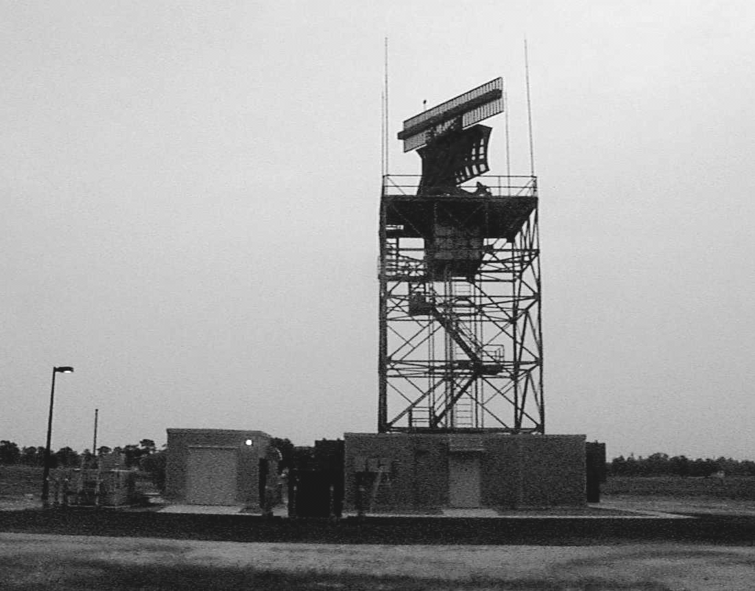 a. Digital Airport Surveillance Radar. DASR will consist of an Antenna Pedestal Group, a Primary System Radar Group, and a System Control and Monitoring/Radar Data Processor.
(1) Antenna Pedestal Group
(a) Primary Antenna. The primary antenna will be a doubly curved reflector with two-beam feed and modified cosecant squared vertical pattern.
(b) Secondary Antenna. The secondary antenna is a high gain planar array, monopulse Large Vertical Aperture antenna which meets FAA vertical coverage, sharp cutoff below beam peak, and Mode-S compatible standards.
(c) Pedestal. The pedestal will have dual drive motors, making it possible to service the alternate motor in the event of failure and still maintain an operational radar. The pedestal also features dual 14-bit optical encoders with individual power supplies.
(2) Primary System Radar Group
(a) Primary System Radar Transmitter. The eight module, all solid-state, coherent transmitter with fault tolerant fail-soft architecture features air cooled, hazard-free, low voltage operation, dedicated power supplies for each module, and built-in fault isolation down to a single Line Replaceable Unit (LRU).
(b) Primary System Radar Receiver. The redundant target and weather receivers use identical radio frequency wide-band receivers and converters operating in the 2700 to 2900 megahertz range with sensitivity time controls programmable from 0 to 72 decibels in six decibel steps.
(c) Signal Data Processor. Dual redundant processors carry out identical tasks synchronously, such that should a processor fail, the failure is transparent to the system. The signal data processor features programmable digital pulse compression with range sidelobes below 50 decibels and preprogrammed and adaptive threshold clutter and beam maps.
(3) System Control and Monitoring/Radar Data Processor. These two functions co-exist on dual redundant workstations.
(a) System Control and Monitoring. Graphic windows of system configuration, system controls, and LRU status are displayed on the workstation color display. Operational controls are accessed via buttons on the various control screens; reconfiguration of the system is available at a single control point accessible to the logged-on maintenance operator with control enabled. All four workstations (two at the radar site and two remote) display the current system status, and all menus apart from adaptation data can be viewed on any of the workstations.
(b) Radar Data Processor. The radar data processor receives track data from the primary surveillance radar and plot data from the secondary surveillance radar. Merging of primary surveillance radar and monopulse secondary surveillance radar tracks takes place if tracks from the two sensors fall within set limits. The on-line radar data processor provides redundant outputs to the radar data remoting equipment in ASTERIX format.
b. Standard Terminal Automation Replacement System. STARS is also known as the DoD Advanced Automated System (DAAS) in the FAA community, but for this document it will be referred to as STARS. STARS will provide a system that maximizes the use of Commercial Off-The-Shelf (COTS) items and Non-Developmental Items (NDI). STARS will provide a fully digital, fault tolerant, high availability system to support essential FAA and DoD Air Traffic Control (ATC) services. STARS is equipped with a single scaleable hardware and software system for all terminal facilities, plus an expandable and extensible platform to support future workloads. User benefit programs are also provided. STARS will improve the efficiency of controllers and maintenance technicians.
(1) Radar Data Processor. The Radar Data Processor (RDP) has two redundant processors (one on-line and one hot standby) mounted in the equipment room rack and interfaced to Full Service Level (FSL) Local Area Networks (LAN). The processor size depends on the number of radar systems: Sun Ultra 1 Model 170 for 0-3 radar systems (small), Sun Ultra 1 Model 200E for 4-13 radar systems (medium), and Sun Ultra 2 Model 1300 for 14-16 radar systems (large). System software handles radar data inputs, processes flight data, and maintains and monitors system tracks.
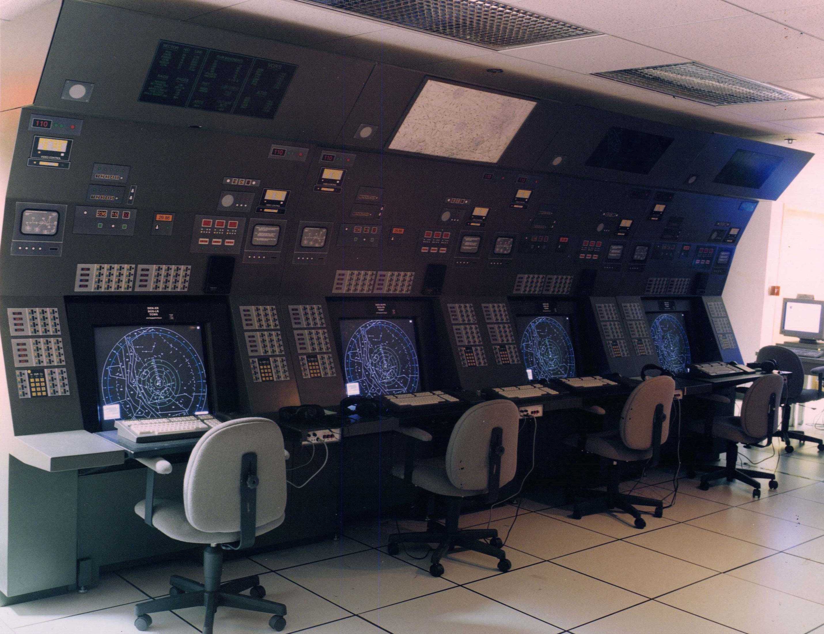
(2) Terminal Controller Workstation. The Terminal Controller Workstation (TCW) consists of one Full Service (FS) Display Processor, one Emergency Service (ES) Display Processor, and one Display Controller-Server mounted in the TCW Console. The ES Display Processor and Controller-Server is the Sun Ultra 1 Model 170. The FS Display Processor depends on the number of radar systems: Sun Ultra 1 Model 170 for 0-3 radar systems (small), Sun Ultra 1 Model 200 for 4-8 radar systems (medium), and Sun Ultra 2 Model 1300 for 9-16 radar systems (large).
(3) Tower Display Workstation. The Tower Display Workstation consists of one FS Display Processor, one ES Display Processor, and one Display Controller-Server mounted in the tower equipment room rack. The ES Display and Controller-Server is the Sun Ultra 1 Model 170E. The FS Display Processor depends on the number of radar systems: Sun Ultra 1 Model 170 for 0-8 radar systems (small) and Sun Ultra 1 Model 200E for 9-16 radar systems (large). Interface to remote towers (greater than 5,000 feet from parent facility) via two or four Government-Furnished Equipment lines.
(4) Monitor and Control Workstation. The Monitor and Control Workstation (MCW) consists of one FS Display Processor, one ES Display Processor, and one Display Server mounted in the MCW computer table in the equipment room. All processors are Sun Ultra 1 Model 200E. The MCW has one standard 21-inch 1024 x 1280 Cathode Ray Tube (CRT) display. The MCW provides control and monitoring display for control system operation, system status display and/or update, system message display, and control playback of recorded system data.
(5) General Purpose Workstation. The General Purpose Workstation (GPW) consists of one Sun Ultra 1 Model 170 with integrated graphics controller, one standard 21-inch 1024 x 1280 CRT display, and a Pseudo-pilot GPW for Pseudo-pilot position assigned training scenario flights to control in response to trainee position controller directions. Contract quantities provide for one Pseudo-pilot for each training TCW.
(6) Test and Training Simulator. The Test and Training Simulator consists of the Sun Ultra 1 Model 200E, and communicates with Pseudo-pilot GPWs via the supporting LAN. The Simulator creates simulated system inputs from scenario generation tools for use by FSL and ESL to aid in certification, test, and training of controllers. The Simulator has optional voice recognition and synthesis capability.
(7) Site Support Server. The Site Support Server (SSS) consists of the Sun Ultra 1 Model 200E with archival tape storage. Sites with less than three radar systems will have five Gigabit Digital Audio Tape (GB DAT), and sites with three or more radar systems will have 30 Gigabit Digital Linear Tape (GB DLT). SSS provides storage of Site Adaptation Data Files.
(8) Data Recording Equipment. The Data Recording Equipment (DRE) has two redundant Sun Ultra 1 Model 200E processors (one on-line and one hot standby), each with two tape drives. Each tape drive can record at least 24 hours of system data. Sites with less than three radar systems will have five GB DAT and sites with three or more radar systems will have 30 GB DLT.
(9) Peripheral Equipment
(a) Printer. The printer is the HP LaserJet 4MV, 16ppm, and 600dpi.
(b) Equipment Racks. Equipment racks come in two sizes, 6-foot and 3.5-foot racks. They are made of steel with a Plexiglas front door, and include a steel rear-access door. They are equipped with two independent, Alternating Current power feeds with Power Conditioning Units (PCU). The six-foot rack dimensions are 73.62" High (H) x 22.56" Wide (W) x 31.56" Deep (D) for the full service rack assembly and the local tower processor rack assembly. The 3.5-foot rack dimensions are 43.87" H x 22.56" W x 31.56" D for the workstation hub rack assembly, and the remote tower processor and automation rack assembly.
(10) Communications Gateway Equipment. The Communications Gateway Equipment (CGE) has dual redundant Sun Ultra 1 Model 170 processors (two each for ESL and FSL). Modem Sharing Units (MSU) split Air Route Traffic Control Center (ARTCC), Enhanced Traffic Management System (ETMS), and radar inputs for redundant ESL and FSL equipment (radar only for ESL). Processing includes Radar and ARTCC message validation and processing, Radar data rho-theta filtering, and multi-scan radar correlation.
(11) Network Equipment. Network equipment utilizes Ethernet LAN (both 100 and 10 Mbps) over twisted pair and/or fiber optics, plus a combination of switches, hubs, and routers. Units are stackable; the modular design allows for addition of components for specific site configurations. The units act as Server Network Management Protocol agents reporting to STARS monitor and control. Firewalls and routers provide network security.
c. Visual Information Display System. VIDS is a Commercial Off-The-Shelf network integration of many small systems used in an ATC facility. VIDS is a client server-based system integrating multiple information systems into a Touch Entry display for each operating position in ATC facilities.
VIDS uses redundant file servers with hubs, workstations, video integration components, audio components, 100BaseT Ethernet, and fiber optics to interface and manage all the system data. The network operating system is Windows NT 4.0. The display software was developed to support the requirements of each system interfacing with VIDS to maximize the information available to the user.
VIDS will consolidate the processing, control, and display of information for the following systems:
- ID-2446/U Master Wind Speed and Direction Indicator (WSDI)
- ML-661/F Digital Altimeter Setting Indicator (DASI)
- AN/FSA-7 Airfield Lighting Control System (AFLCS)
- Automated Terminal Information System (ATIS)
- SG-1064 Facility Time Code Generator (TCG)
- Automated Surface Observation System (ASOS)
- AN/GMQ-27 Weather Vision and/or Meteorological Information Distribution System (MIDS)
- FA-10095 FAA FDIO
- Remote Video Cameras
- Air Traffic Activity Analyzer (ATAA)
VIDS will replace the following system components in the control tower:
- ID-2447A/U Slave WSDIs
- ID-2423/F DASI Displays
- AN/FSA-7 AFLCS display, keyboard, trackball, and the Central Processor Unit (CPU)
- ATIS System
- ID-2384G and ID-2396 Clock Displays
- Weather Vision/MIDS Display
- FA-10095 FDIO, display, keyboard, and printer
- Remote Video Camera Displays and Controls
- ATAA display, keyboard, and printer
VIDS will automate the following control tower administrative functions using a centralized database:
- Daily Operations Log - FAA Form 7230-4
- Position Log - FAA Form 7230-10
- ATAA
2. Physical Description
a. Digital Airport Surveillance Radar. The DASR system includes the Prime Mission Equipment (PME) and facilities. The DASR PME includes the Primary Surveillance Radar (PSR) with weather channels, Monopulse Secondary Surveillance Radar (MSSR), PSR and MSSR antennas, operator maintenance terminals, surveillance data displays, modems, and surveillance data translators, with video display control units. The facilities are the tower, equipment shelter, power distribution system, uninterruptible power supply, engine generator, and interconnecting cabling. Ancillary equipment includes the PSR moving target indicator with towers and housing, the MSSR remote systems monitor with tower, housing, and local and remote control panels.
|
COMPONENT |
LENGTH (FEET) |
WIDTH (FEET) |
HEIGHT (FEET) |
WEIGHT (POUNDS) |
|
Engine-Generator Set |
12 |
15 |
10 |
41,000 |
|
Pre-fabricated Shelter |
30 |
12 |
10 |
82,000 |
Note: The physical dimensions of the remaining components will be added in future updates to this NTSP, as information becomes available.
b. Standard Terminal Automation Replacement System. The physical size of each STARS component is not available at this time. However, all equipment will fit within the two different size equipment racks provided. SPAWARSYSCEN Charleston conducted a site survey of the schoolhouse at NATTC Pensacola during Fiscal Year (FY) 99 to determine the physical constraints associated with the classroom and lab space to be used for the STARS maintenance course. The results are not yet available.
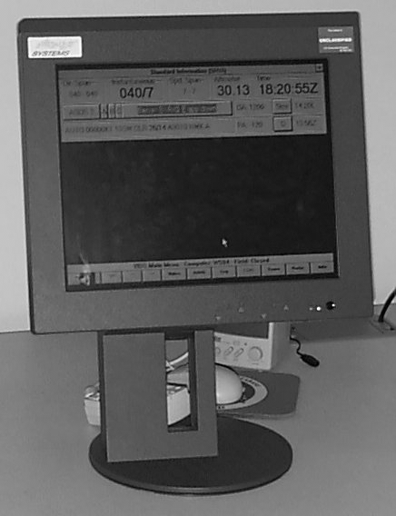
c. Visual Information Display System. VIDS contains a Standard Information Window that provides basic safety of flight information to the controller. This information is provided by live sensor data from the incorporated air traffic control systems. The Standard Information Window is normally located at the top of the Air Traffic Controller's display, and can be sized using the "Size" button to suit the operator's preference. Due to the critical nature of the information displayed, no other system window can cover the Standard Information Window.
VIDS also displays a main menu bar that provides a central point for the user to perform commonly occurring operations. It consists of a set of 11 buttons and is located near the bottom of the controller's display.
3. New Development Introduction. The NASMOD components are NDI, consisting of modified COTS equipment.
4. Significant Interfaces. The DASR will interface with the existing Navy Beacon System to obtain status and target plot outputs. The DASR will also interface with the STARS and the VIDS when they are introduced to the fleet.
5. New Features, Configurations, or Material. Not Applicable (NA)
H. CONCEPTS
1. Operational Concept. Operator duties for the NASMOD components consist of energizing and de-energizing the equipment. These actions will be performed by Navy Air Traffic Controllers (AC) with Navy Enlisted Classification (NEC) 6901, Marine Corps personnel with Military Occupational Specialty (MOS) 7257 or 7291, and civilian DoD personnel assigned to the Air Operations Department.
2. Maintenance Concept. The NASMOD components will be maintained using a two level maintenance concept, organizational and depot.
a. Organizational. Navy personnel in the Electronics Technician (ET) rating with NEC 15XX and Marine Corps personnel with MOS 5953 will perform on-site organizational level maintenance. This will include fault isolation and troubleshooting prime mission equipment as well as any required servicing, aligning, cleaning, and lubricating.
(1) Preventive Maintenance. Preventive maintenance consists of periodic inspections and servicing per applicable Maintenance Requirements Cards. Most preventive maintenance will be accomplished with the components in the operational state and without degrading system performance. Cleaning and lubrication of the rotary joint slip ring of the DASR will require that the system be shut down.
(2) Corrective Maintenance. Corrective maintenance will include on-equipment and off-equipment maintenance actions. On-equipment maintenance consists of fault isolation and removal and replacement of faulty LRUs in an operational environment. Off-equipment maintenance will include limited repair of Shop Replaceable Units (SRU) when failures can be isolated using Built-In Test and limited support equipment and technical data.
b. Intermediate. NA
c. Depot. Depot maintenance will consist of repairing failed LRUs and SRUs down to the piece part level. Depot maintenance may also include emergency maintenance, engineering support, and other logistics support not available at the organizational level. Initially, the contractor will provide all depot level maintenance functions. The FAA intends to establish an organic depot at the FAA Logistics Center in Oklahoma City, Oklahoma, for all DoD and FAA DASR systems by FY05.
d. Interim Maintenance
1. DASR. The contractor (Raytheon) will provide Interim Contractor Support (ICS). Future plans for parts acquisition via the Federal Aviation Administration Logistics Center (FAALC) 24-hour help desk are in place. The sites will contact the ISEA or the FAALC To Be Determined (TBD) for technical assistance.
2. STARS. The FAA depot is scheduled to be established by November 2001 and thus no interim support is anticipated to be required for Navy sites. STARS will have a one-year warranty that will be in effect after system acceptance from Raytheon at SPAWAR Systems Center Charleston (SSCC).
3. VIDS. SSCC will provide VIDS interim maintenance support.
e. Life Cycle Maintenance Plan. TBD
3. Manning Concept. Introduction of the NASMOD components will have no impact to the current manning levels for operators or maintainers in the Navy and Marine Corps. The Navy will establish a new NEC, ET-15XX - DASR/STARS Maintenance Technician. ET personnel currently having NEC 1574, 1578, or 1580 will initially fill these billets.
4. Training Concept. The object of the DASR/STARS training is to provide trained DASR/STARS maintenance technicians and operators to shore-based Navy and Marine Corps approach control facilities. The contractor will provide initial training for Operational Test and Evaluation (OT&E) personnel, site installation team members, and other key personnel. Initial maintenance training will be provided to NATTC Pensacola instructors concurrent with the installation of the first set of Technical Training Equipment (TTE). Follow-on DASR/STARS maintenance training for Navy ETs will be accomplished by developing a new DASR/STARS maintenance training track, C-103-XXXX, DASR/STARS Maintenance Technician Pipeline, which will be phased-in over a five-year period beginning in May 2002. The following three existing courses will be phased-out on a parallel schedule:
- C-103-2060, AN/GPN-27 Radar Maintenance Technician Pipeline
- C-103-2051, AN/TPX-42A(V)10 RATCF DAIR Maintenance Technician Pipeline
- C-103-2053, AN/TPX-42A(V)5 DAIR Maintenance Technician Pipeline
The current Marine Corps pipeline, C-103-2080, Marine Air Traffic Control Radar Technician Pipeline, will not change with the introduction of the NASMOD components.
The established training concept for most aviation maintenance training divides "A" School courses into two or more segments called Core and Strand. Many organizational level "C" School courses are also divided into separate Initial and Career training courses. "A" School Core courses include general knowledge and skills training for the particular rating, while "A" School Strand courses focus on the more specialized training requirements for that rating and a specific aircraft or equipment, based on the student's fleet activity destination. Strand training immediately follows Core training and is part of the "A" School. Upon completion of Core and Strand "A" Schools, graduates going to organizational level activities attend the appropriate Initial "C" School for additional specific training. Initial "C" School training is intended for students in paygrades E-4 and below. Career "C" School training is provided to organizational level personnel, E-5 and above, to enhance skills and knowledge within their field. ("A" School graduates going to intermediate level activities attend the appropriate intermediate level "C" School. Intermediate level "C" Schools are not separated into Initial and Career courses.)
a. Initial Training. Initial basic operator and maintenance training will be accomplished during installation at each site. This two-day installation and checkout course will focus on the Software User's Guide and On-the-Job Training (OJT) for STARS and VIDS.
(1) Operational Test and Evaluation Training. This training consisted of the DASR Site Maintenance Course with a two-week add-on. It was structured to specifically support the government's objectives for conducting OT&E.
|
Title |
Operational Test and Evaluation Course |
|
Description |
This training focuses on the skills needed to conduct government OT&E. |
|
Location |
Raytheon Canada Limited, Waterloo |
|
Length |
9 weeks |
|
RFT date |
January 1999 |
|
Prerequisites |
ET 1580 |
(2) Installation Training. System installation training for SPAWARSYSCEN personnel was conducted as follows:
|
Title |
Installation and Checkout Course |
|
Description |
This course provides DASR installation topics, including:
|
|
Location |
Raytheon Canada Limited, Waterloo |
|
Length |
2 weeks |
|
RFT date |
July 2000 |
|
Prerequisites |
DASR Site Maintenance Course |
(3) Maintenance Training. Initial maintenance training was conducted as follows:
|
Title |
DASR Site Maintenance Course |
|
Description |
This course provides the skills and knowledge required to perform both on-equipment and off-equipment organizational level maintenance on the DASR, including:
|
|
Location |
Raytheon Canada Limited, Waterloo |
|
Length |
7 weeks |
|
RFT date |
January 1999 |
|
Prerequisites |
|
(4) Operator Training. Operator training for ACs and Marine Corps personnel with MOS 7257 or 7291 is being accomplished using Computer-Based Training (CBT). This simulator software is provided to each site during DASR installation. The course takes approximately four to eight hours to complete and can be run on any Personal Computer with the following specifications: 486 or higher, Windows 95 or higher, 16 megabytes RAM, and a monitor with a resolution of 1024 x 768 using small fonts.
b. Follow-on Training. A training videotape and copies of all contractor training materials will be delivered to the Navy for use in course development.
(1) Operator. NATTC Pensacola trains Navy and Marine Corps Air Traffic Controllers for the fleet. The current Air Traffic Controller (AC) "A1" and Advanced Radar Air Traffic Control (ARATC) "C" school classroom curricula will require updating as VIDS is deployed to Navy and Marine Corps ATC facilities. More importantly, the AC "A1" Tower Operator Training System (TOTS) laboratories and the ARATC "C" school laboratory will require installation of a VIDS-like Training Device (TD) to properly support training requirements. This TD must be capable of interfacing with existing 15G31 (for ARATC) and 15G32 for AC "A1" TOTS. This installation should occur at the same time that approximately 50 percent of the Navy and Marine Corps ATC Facilities are equipped with VIDS (FY03).
Navy personnel in the AC rating and Marine Corps operators earn NEC 6901 and MOS 7257, respectively, upon completion of advanced air traffic control schools and certification to perform required tasks. When VIDS and STARS have been installed at 50 percent of the Navy and Marine Corps ATC facilities in the fleet, the current advanced "C" school course will begin training the VIDS and STARS as a stand-alone course, and phase-out the existing course. Since VIDS and STARS are an upgrade and consolidation of existing functions that an operator would normally perform, there will be no requirement for a new operator NEC or MOS.
The following ATC courses are available for Navy and Marine Corps operators. These courses will be modified and stand-up when fleet ATC facilities are 50 percent operational with VIDS and STARS. Training Equipment Change Requests (TECR) #N42146-99-2546 and 2547 have been submitted but have not been funded at this time.
|
Title ......................... |
Air Traffic Controller |
|
CIN .......................... |
C-222-2010 |
|
Model Manager ........ |
NATTC Pensacola |
|
Description ............... |
This course provides Navy and Marine Corps personnel with the basic tower and radar control technical knowledge and skills to meet FAA requirements and certification, including:
Upon completion, the student will have the knowledge to perform as an apprentice Air Traffic Controller in a base operations, control tower, or terminal radar environment. |
|
Location ................... |
NATTC Pensacola |
|
Length ...................... |
110 days |
|
RFT date .................. |
Currently available |
|
Skill identifier ........... |
None |
|
TTE/TD ................... |
A VIDS-like TD is necessary in the TOTS laboratories, capable of interfacing with existing 15G32 TD. TECR #N42146-99-2547 was submitted in August 1999 and remains unfunded. |
|
Prerequisites ............. |
|
|
Title ......................... |
Advanced Radar Air Traffic Control |
|
CIN .......................... |
C-222-2022 |
|
Model Manager ........ |
NATTC Pensacola |
|
Description ............... |
This course provides selected Air Traffic Control personnel with advanced knowledge in airspace management, navigational equipment, basic knowledge in Terminal Instrument Approach Procedures (TERPS), and the technical knowledge and practical application of procedures used at various control positions of a Radar Air Traffic Control Facility. Training includes:
Upon completion, the student will be able to perform the duties of an Air Traffic Control Specialist. |
|
Location ................... |
NATTC Pensacola |
|
Length ...................... |
26 days |
|
RFT date ................... |
Currently available |
|
Skill identifier ........... |
|
|
TTE/TD ................... |
A VIDS-like TD is necessary in the ARATC "C" school laboratory, capable of interfacing with existing 15G31 TD. TECR #N42146-99-2546 was submitted in August 1999 and remains unfunded. A STARS simulator will be used as TD. |
|
Prerequisites ............. |
|
(2) Maintainer. NATTC Pensacola currently has two maintenance technical pipelines that will become obsolete once VIDS and STARS are deployed to Navy and Marine Corps ATC facilities. A new STARS Maintenance Technician Pipeline will stand up and a new NEC established to support VIDS/STARS training requirements. The current NECs for the Basic Direct Altitude and Identity Readout (DAIR) and Radar Air Traffic Control Facility (RATCF) DAIR systems will be gradually phased-out as VIDS and STARS are installed at ATC facilities. Marine Corps personnel with MOS 5953 will attend the Navy maintenance training courses at NATTC Pensacola, as requirements dictate. A new MOS will not be required.
|
Title ......................... |
AN/TPX-42(V)5 DAIR Maintenance Technician Pipeline |
|
CIN .......................... |
C-103-2053 |
|
Model Manager ........ |
NATTC Pensacola |
|
Description ............... |
This course provides training for the Electronics Technician, including:
Upon completion, the student will be able to perform Air Traffic Control equipment maintenance under limited supervision. |
|
Location ................... |
NATTC Pensacola |
|
Length ...................... |
70 days |
|
RFT date .................. |
Currently available |
|
Skill identifier ........... |
ET 1574 |
|
TTE/TD ................... |
Basic DAIR System |
|
Prerequisites ............. |
A-100-0140, ET Strand "A" School or equivalent fleet experience |
|
Title ......................... |
AN/TPX-42(V)10 RATCF DAIR Maintenance Technician Pipeline |
|
CIN .......................... |
C-103-2051 |
|
Model Manager ........ |
NATTC Pensacola |
|
Description ............... |
This course provides training for the Electronics Technician, including:
Upon completion, the student will be able to perform Air Traffic Control equipment maintenance under limited supervision. |
|
Location ................... |
NATTC Pensacola |
|
Length ...................... |
89 days |
|
RFT date .................. |
Currently available |
|
Skill identifier ........... |
ET 1578 |
|
TTE/TD ................... |
RATCF DAIR System |
|
Prerequisites ............. |
A-100-0140, ET Strand "A" School or equivalent fleet experience |
|
Title ......................... |
AN/GPN-27 Radar Maintenance Technician Pipeline |
|
CIN .......................... |
C-103-2060 |
|
Model Manager ........ |
NATTC Pensacola |
|
Description ............... |
This course provides training for the Electronics Technician, including:
Upon completion, the student will be able to perform the duties of an AN/GPN-27 Radar Maintenance Technician under limited supervision. |
|
Location ................... |
NATTC Pensacola |
|
Length ...................... |
101 days |
|
RFT date .................. |
Currently available |
|
Skill identifier ........... |
ET 1580 |
|
TTE/TD ................... |
The AN/GPN-27 Radar system is used as TTE. |
|
Prerequisites ............. |
A-100-0140, ET Strand "A" School or equivalent fleet experience |
|
Title ......................... |
Marine Air Traffic Control Radar Technician Pipeline |
|
CIN .......................... |
C-103-2080 |
|
Model Manager ........ |
NATTC Pensacola |
|
Description ............... |
This course provides training for the Electronics Technician, including:
Upon completion, the student will be able to perform the duties of a Marine Air Traffic Control Radar Technician under limited supervision. |
|
Location ................... |
NATTC Pensacola |
|
Length ...................... |
247 days |
|
RFT date .................. |
Currently available |
|
Skill identifier ........... |
MOS 5953 |
|
TTE/TD ................... |
NA |
|
Prerequisites ............. |
C-100-2019, Marine Air Traffic Control Basic Technician |
Note: VIDS and STARS will be used as TTE for the VIDS and STARS maintenance course that replaces the DAIR and RATCF courses. The installation of the TTE is scheduled for second quarter FY00 for the first system and FY04 for the second system.
c. Student Profiles
|
SKILL IDENTIFIER |
PREREQUISITE SKILL AND KNOWLEDGE REQUIREMENTS |
|
AC 6901 |
C-222-2010, Air Traffic Controller |
|
ET 1574 |
|
|
ET 1578 |
|
|
ET 1580 |
|
|
MOS 5953 |
|
|
MOS 7257 |
|
d. Training Pipeline
|
Title |
DASR/STARS Maintenance Technician Pipeline |
|
CIN |
C-103-XXXX |
|
Model Manager |
NATTC Pensacola |
|
Description |
This pipeline provides training in the maintenance of the DASR and the STARS. |
|
Location |
NATTC Pensacola |
|
Length |
16 weeks (approximately) |
|
RFT date |
May 2002 |
|
Skill identifier |
ET 15XX |
|
TTE/TD |
DASR will be installed in October 2001. |
|
Prerequisites |
|
Note: The DASR/STARS Maintenance Technician Pipeline will consist of the following courses:
- C-103-2045, Air Traffic Control Maintenance Preparatory
- C-103-2026, Miniature Component Repair
- C-103-XXX2, AN/FAC-6(V)2 Fiber Optic Inter-site Maintenance
- C-103-XXXX, DASR Maintenance
- C-103-2XXX, STARS Maintenance
NEC 15XX will be awarded once all NASMOD equipment and curriculum is in place at NATTC Pensacola to support the establishment of the new maintenance training pipeline.
I. ONBOARD (IN-SERVICE) TRAINING
1. Proficiency or Other Training Organic to the New Development
a. Maintenance Training Improvement Program. Maintenance Training Improvement Program (MTIP) is a training management tool that, through diagnostic testing, identifies individual training deficiencies at the organizational and intermediate levels of maintenance. MTIP was implemented per OPNAVINST 4790.2 series. MTIP will be replaced by the Aviation Maintenance Training Continuum System (AMTCS). Current planning is for AMTCS to begin full implementation for fleet deployment in March 2001.
b. Aviation Maintenance Training Continuum System. AMTCS will provide career path training to the Sailor or Marine from their initial service entry to the end of their military career. AMTCS is planned to be an integrated system that will satisfy the training and administrative requirements of both the individual and the organization. The benefits will be manifested in the increased effectiveness of the technicians and the increased efficiencies of the management of the training business process. By capitalizing on technological advances and integrating systems and processes where appropriate, the right amount of training can be provided at the right time, thus meeting the CNO's mandated "just-in-time" training approach.
Technology investments enable the development of several state-of-the-art training and administrative tools: CBT for the technicians in the Fleet in the form of Interactive Courseware (ICW) with Computer Managed Instruction (CMI) and Computer Aided Instruction (CAI) for the schoolhouse.
Included in the AMTCS development effort is the Aviation Maintenance Training Continuum System - Software Module (ASM) which provides testing [Test and Evaluation (TEV)], recording [Electronic Training Jacket (ETJ)], and a Feedback system. The core functionality of these AMTCS tools are based and designed around the actual maintenance-related tasks the technicians perform, and the tasks are stored and maintained in a Master Task List (MTL) data bank. These tools are procured and fielded with appropriate COTS hardware and software, i.e., Fleet Training Devices (FTD) - Laptops, PCs, Electronic Classrooms (ECR), Learning Resource Centers (LRC), operating software, and network software and hardware.
Upon receipt of direction from OPNAV (N789H), AMTCS is to be implemented and the new tools integrated into the daily training environment of all participating aviation activities and supporting elements. AMTCS will serve as the standard training system for aviation maintenance training within the Navy and Marine Corps, and is planned to supersede the existing MTIP and Maintenance Training Management and Evaluation Program (MATMEP) programs. AMTCS implementation will begin with the F-14, E-2C, and all models F/A-18 aircraft. For more information on AMTCS refer to PMA205-3D3.
2. Personnel Qualification Standards. Personnel Qualification Standards (PQS) are not envisioned for STARS and VIDS maintenance technicians, or Air Traffic Controllers. The PQS Development Group, Naval Education and Training Professional Development and Technology Center, Pensacola, Florida, will update PQS for maintenance personnel with the DASR information provided by NATTC Pensacola.
3. Other Onboard or In-Service Training Packages. The NASMOD information will be integrated into existing operator OJT packages. Each of the Navy and Marine Corps approach control facilities has an OJT program that has been custom-tailored to their operational requirements and physical airfield layout.
Marine Corps onboard training is based on the current series of MCO P4790.12, Individual Training Standards System and the MATMEP. These programs are designed to meet Marine Corps, as well as Navy OPNAVINST 4790.2 series, maintenance training requirements. It is a performance-based, standardized, level-progressive, documentable, training management and evaluation program. It identifies and prioritizes task inventories by MOS through a front-end analysis process that identifies task, skill, and knowledge requirements of each MOS. MTIP questions coupled to MATMEP tasks will help identify training deficiencies that can be enhanced with refresher training. MATMEP will be replaced by the AMTCS.
J. LOGISTICS SUPPORT
1. Manufacturer and Contract Numbers
|
CONTRACT NUMBERS |
MANUFACTURER |
ADDRESS |
|
F19628-96-D-0038 DTFA01-96-D-03008 |
Raytheon Company Electronic Systems |
1001 Boston Post Road Marlboro, MA 01752-3789 |
2. Program Documentation. NA
3. Technical Data Plan. The contractor will design technical manuals that provide the full range and depth of coverage to support the NASMOD components. The Operations and Maintenance Manual will describe the integration of all NDI and COTS equipment into a single system. The Field Installation Manual will provide the procedures and information required for non-turnkey installation by SPAWARSYSCEN personnel at all Navy and Marine Corps facilities. Two sets of these manuals (paper and CD-ROM) will be delivered with each system along with one set of commercial manuals for all NDI and COTS equipment used. The Planned Maintenance System will be developed by SPAWARSYSCEN and will consist of Maintenance Index Pages and Maintenance Requirements Cards.
4. Test Sets, Tools, and Test Equipment. A Lifting Beam and a Tilting Adjuster manufactured by Cossor Electronics Limited are both required for removal and tilt adjustment of the Secondary Surveillance Radar Antenna. Currently, the FAA plans to procure only one of each and to store these items at the FAA Logistics Center in Oklahoma City. This will require the DASR sites to requisition this equipment each time it is needed. Due to Navy peculiar requirements it may be necessary to purchase two subsets of this equipment so that the Navy can retain one subset on each coast. There is also a Mono-pulse Beacon Test Set that is being acquired for the purpose of certifying the Mono-pulse Secondary Surveillance Radar for operation in the National Airspace System. Acquisition of the Mono-pulse Beacon Test Set is still under contract. Refer to element IV.A.1 for further information.
5. Repair Parts. Onboard critical item spares will be provided during installation; interim supply support will be provided by SPAWARSYSCEN Charleston, to ensure repair part support, initial, interim, and follow-on secondary item spares are budgeted. A Material Support Date (MSD) for each NASMOD component will be established and supply support, will transition to the Naval Inventory Control Point Philadelphia, Pennsylvania.
6. Human Systems Integration. Since the NASMOD components are an NDI, modified COTS acquisition, it will be difficult to change the current design of the system. Human Systems Integration will be utilized during evaluation of current facilities and new construction to take into account human engineering and equipment accessibility, and provide working clearance and space as required by safety regulations.
K. SCHEDULES
1. Installation and Delivery Schedules. The installation schedule below shows either completed or proposed dates. Proposed dates may change based on design changes and equipment availability.
|
LOCATION |
VIDS |
STARS |
DASR |
|
NAWC St. Inigoes (OSF) |
1999 |
2000 |
NA |
|
NATTC Pensacola (1) |
2000 |
2001 |
2001 |
|
NATTC Pensacola (2) |
2001 |
2005 |
2005 |
|
SPAWARSYSCEN |
1999 |
2001 |
2001 |
|
NAS Meridian |
2000 |
2004 |
2004 |
|
NAS Norfolk |
2001 |
2001 |
NA |
|
NAS Norfolk (Helo) |
2001 |
2001 |
NA |
|
MCAS Camp Pendleton |
2001 |
2001 |
NA |
|
NAS Oceana |
2001 |
2002 |
2002 |
|
NAS Pensacola |
2000 |
2003 |
2003 |
|
NAS JRB Fort Worth |
2001 |
2005 |
2005 |
|
NAS Willow Grove |
2002 |
2002 |
2001 |
|
MCAS Kaneohe Bay |
2002 |
2002 |
2002 |
|
NAS Whidbey Island |
2002 |
2002 |
2002 |
|
NAS Patuxent River |
2002 |
2002 |
2002 |
|
MCAS Beaufort |
2002 |
2002 |
2002 |
|
NALF San Clemente Island |
2002 |
2002 |
2002 |
|
NAS Kingsville |
2006 |
2003 |
2003 |
|
NALF Orange Grove |
2006 |
2003 |
NA |
|
NAS Whiting Field |
2004 |
2003 |
2003 |
|
MCAS Iwakuni |
2003 |
2003 |
2003 |
|
NAS Corpus Christi |
2004 |
2004 |
2004 |
|
NAS Lemoore |
2004 |
2004 |
2004 |
|
NAS North Island |
2006 |
2005 |
2005 |
|
NOLF Imperial Beach |
2006 |
2005 |
NA |
|
NALF Cabaniss |
2004 |
2003 |
NA |
|
NALF Waldron |
2004 |
2003 |
NA |
|
NOLF Choctaw |
2003 |
NA |
NA |
|
MCAS Cherry Point |
2004 |
2003 |
2003 |
|
MCAS New River |
2003 |
2003 |
2003 |
|
NAS Jacksonville |
2005 |
2004 |
2004 |
|
NAS New Orleans |
2006 |
2004 |
2004 |
|
MCAS Yuma |
2004 |
2004 |
2004 |
|
MCAS Miramar |
2005 |
2006 |
NA |
|
NOLF Joe Williams (Bravo) |
2003 |
NA |
NA |
|
NOLF Whitehouse |
2005 |
NA |
NA |
|
NALF Webster |
2002 |
NA |
NA |
|
NAS Fallon |
2006 |
2005 |
2005 |
|
NAWS Point Mugu |
2005 |
2005 |
2005 |
|
NAS Brunswick |
2008 |
2005 |
2005 |
|
NAS Key West |
2003 |
2005 |
2006 |
|
MCAS Futenma |
2008 |
2006 |
2006 |
|
NAVSTA Mayport |
2008 |
2006 |
2006 |
|
NS Roosevelt Roads |
2008 |
2006 |
2006 |
|
MCAF Quantico |
2008 |
2006 |
2006 |
|
NAVSTA Rota |
2006 |
2006 |
2006 |
|
NAS Keflavik |
2008 |
2006 |
2007 |
|
NOLF San Nicolas Island |
2005 |
NA |
NA |
|
NAS El Centro |
2009 |
2007 |
2007 |
|
PMRF Barking Sands |
2003 |
2007 |
NA |
|
NSF Diego Garcia |
2003 |
2007 |
NA |
|
NAVSTA Guantanamo Bay |
2003 |
2007 |
NA |
|
NAWC Lakehurst |
2003 |
NA |
NA |
|
NAWS China Lake |
2003 |
2007 |
NA |
|
SPAWARSYSCEN Trailers |
2007 |
2006 |
NA |
2. Ready For Operational Use Schedule. The NASMOD Components will be ready for operational use after successful installation, test, and certification by the installation crew. The air station ATC Operations Department will witness test and certification procedures where possible.
3. Time Required to Install at Operational Sites. Installation of the DASR is currently planned to be in conjunction with the installation of the STARS and the VIDS. Time required for completion of the DASR installation will be between 34 and 54 days per site. Early STARS systems will be installed independently. STARS systems will be installed in conjunction with DASR systems beginning in Calendar Year (CY) 02. Installing the two systems together eliminates disrupting facility operations more than once for each system installation. SPAWARSYSCEN Charleston estimates the installation process will take five months. This includes setting up temporary ATC facilities if required, installing STARS and DASR, and the initial test and check of the new systems. Installation at each site will be accomplished via one of three methods listed below:
(1) First method. The concurrent approach method involves the installation of replacement systems side-by-side with the existing operational equipment. This method allows the current ATC equipment to remain fully operational while the new equipment is being installed and tested. It requires sufficient floor space available for parallel equipment installation, sufficient power for existing and replacement equipment, and sufficient Heating, Ventilation, and Air Conditioning (HVAC) capacity for existing and replacement equipment. Upon successful installation, test, and certification of the new equipment the facility transitions over to the new system for operational use, and the old systems are removed.
(2) Second method. The Marine Air Control Squadron (MACS) approach can be used when the concurrent approach method is not feasible due to facility space limitations. The MACS unit deploys to the airfield being upgraded and sets up mobile ATC equipment. Once the MACS is operational, control of all ATC operations is transferred to the MACS, and the old equipment is shut down for removal and replacement. MACS requirements include six months advanced scheduling; ample telephone landline circuits available at the MACS site; and messing, berthing, and transportation for MACS operators and maintainers. Requirements also include a letter of agreement between the MACS and Air Station-Air Operations, accurate field data in advance for the efficient setup and generation of video maps, and time for station controllers to train on MACS equipment and familiarize MACS controllers with local operations. Upon successful installation, test, and certification of the new equipment, the facility transitions over to the new system for operational use.
(3) Third method. The Transportable Air Traffic Control Facility (TATCF) Approach can be utilized when the concurrent approach is not technically feasible and no MACS unit is available. This approach involves the construction of mobile trailers with standard Navy ATC processing, display, communications control, and ancillary equipment. After the TATCF is set up, tested, and certified at an air station, control of the radar operations will be turned over to the TATCF and the old radar facility equipment will be removed and replaced with the new system. Requirements include construction of two sets of TATCF trailers, each with a full complement of standard Navy ATC systems, sitting close to the existing facility, with sufficient power for the trailers. The TATCF will interface with the existing Precision Approach Radar, Airport Surveillance Radar, radios, and telephone landline circuits. Following successful testing and certification of the new systems, control is transferred back to the new equipment in the RATCF and ATC Tower.
4. Foreign Military Sales and Other Source Delivery Schedule. For Air Force, Army, or FAA delivery schedules contact the Developing Agency, NAVAIRSYSCOM, PMA213.
5. Training Device and Technical Training Equipment Delivery Schedule
(1) Maintenance Training. Two AN/FSQ-204 STARS systems will be delivered to NATTC Pensacola to support maintenance training. One system will be installed in CY01 and the second in CY05. Coordination between the NATTC Project Manager and SPAWARSYSCEN Charleston is required for relocation of AN/FSC-104 ECS radio antennas to ensure proper maintenance course lab space for STARS equipment. Two DASR systems will be installed at NATTC Pensacola. The first will be Ready For Operational Use (RFOU) in October 2001 and the second will be RFOU in August 2005. These systems will be the primary TTE. No new training devices will be required to support the DASR training. VIDS TTE for the STARS Maintenance Technician course is required in FY00 for the first system and FY04 for the second.
(2) Operator Training. Training Device 15G31 Shore-based Radar ATC Training Systems supporting AC "A1" laboratory and ARATC "C" laboratory instruction must be modified to replicate STARS operations. This modification will be developed by NAWC TSD Orlando, Florida, and will be in place when 50 percent of the Navy and Marine Corps STARS installations are complete. VIDS-like TD for the AC "A1" TOTS laboratories and the ARATC "C" school laboratory should occur at the time that 50 percent of Navy and Marine Corps ATC facilities are equipped with VIDS (FY03).
L. GOVERNMENT-FURNISHED EQUIPMENT AND CONTRACTOR-FURNISHED EQUIPMENT TRAINING REQUIREMENTS. NA
M. RELATED NTSPs AND OTHER APPLICABLE DOCUMENTS
|
DOCUMENT OR NTSP TITLE |
DOCUMENT OR NTSP NUMBER |
PDA CODE |
STATUS |
|
Statement of Operational Need |
USAF SON 001-85 |
Air Force |
Approved 11 Jun 87 |
|
Operational Requirements Document |
USAF ORD 04-87 |
Air Force |
Approved 14 May 92 |
|
Naval and Marine Corps Air Traffic Control Facility Transition Program |
NA |
SPAWARSYSCOM Code 313 |
Approved Dec 96 |
|
DASR Integrated Logistics Support Plan |
ATC-ILSP-011 |
SPAWARSYSCOM |
Approved Jul 98 |
|
STARS Phase II Operational Requirements Document (ORD) |
NA |
Joint Program Office (JPO) |
Approved 18 Jun 95 |
|
U.S. Department of Transportation FAA and DoD STARS Phase III (Final) ORD |
NA |
Joint Program Office (JPO) |
Approved 30 May 96 |
|
AN/GPN-27 Airport Surveillance Radar |
N-88-NTSP-A-50-7902A |
PMA213 |
Approved 28 Sep 89 |
|
AN/TPX-42A(V)5/10 |
N-88-NTSP-E-50-7005F |
PMA205 |
Approved 6 Jan 94 |
|
Enhanced Terminal Voice Switch (ETVS) |
N-88-NTSP-A-50-9701A |
PMA205 |
Approved Apr 99 |
|
NEWSLETTER
|
| Join the GlobalSecurity.org mailing list |
|
|
|