Chapter 15
SAFETY
AR 385-63 (MCOP3570.1A), Chapter 11, implements the chain-of-command safety concept. Under this concept, the firing battery chain of command is responsible for safety during firing, training, and combat. This chapter reinforces AR 385-63. However, if local range regulations are more restrictive than the material in this chapter, the local range regulations must be followed.
Section I
Responsibilities and Duties
This section describes safety responsibilities, the duties of safety personnel, and the safety aids used by those personnel.
15-1. Responsibilities
a. Commanders of Field Artillery Units. Commanders establish and maintain a safety training and certification program for their personnel. The purpose of this program is to train and qualify personnel of the firing battery in the safety procedures for their specific areas of responsibility. When the commander is satisfied that the personnel are qualified to perform the safety duties as required, he certifies them.
b. Battalion Commander. The FA battalion commander is responsible for safety during all phases of a firing exercise under his control. He selects, trains, and certifies the personnel needed to help him discharge this responsibility. These personnel include, but are not limited to, the following:
- Battery commander.
- Executive officer.
- Fire direction officer.
- XO or platoon leader.
- Chief of firing battery.
- Gunnery sergeant.
- FDC chief computer.
- Howitzer section chief.
If any position is not filled by a command safety-certified individual, another individual who is certified and qualified to fill that position performs the safety checks.
c. Officer in Charge. The officer in charge (OIC) is the battery commander or his command safety-certified representative. The OIC is responsible for all aspects of safety in the firing unit and on the assigned firing range. Before the firing exercise, the range officer provides the OIC with the required safety data and any firing limitations. The OIC verifies that the unit is in the proper firing position. He supervises the conversion of the safety data into a safety diagram and ensures that this diagram is verified by another command safety-certified individual. The safety data determined from the safety diagram provide right and left deflection limits, minimum and maximum quadrant elevations for authorized charges, and minimum safe fuze times. The safety T, modified as needed by the XO's minimum QE, is given to the appropriate members of the firing battery.
d. XO or Platoon Leader. The XO or platoon leader is responsible for the safety practices of the firing element. He ensures that the section chiefs have safety data. He is responsible for determining the lowest QE that can be fired safely from his firing position and will ensure that projectiles clear all immediate crests (XO's minimum QE). He is assisted by the FDO, the platoon sergeant, and/or the gunnery sergeant.
e. Fire Direction Officer. The FDO has primary responsibility for computing safety data and for ensuring that all safety data are updated after registrations and receipt of current met data. He is responsible for plotting the impact area on a map or chart in the FDC. He is assisted in his duties by the chief computer. He ensures that all firing data are within prescribed safety limits before they are sent to the firing sections. He is responsible for adjusting minimum QE for intervening crests.
f. Platoon Sergeant. The platoon sergeant helps the XO or platoon leader in his duties and must be prepared to perform many of the duties in his absence. His main responsibilities are laying the battery, performing the duties of the XO or platoon leader, and working in shifts with the XO or platoon leader.
g. Howitzer Section Chief. The section chief is responsible for supervising all practices that take place at or near his weapon. These include verifying that the announced safety data are applied to his weapon and that the proper charge, fuze, and projectiles are fired. He has the final responsibility for the firing of his weapon.
h. Range Officer. The range officer gives the OIC of the firing unit the following safety data:
- Grid coordinates of the firing position.
- Lateral safety limits.
- Minimum and maximum ranges.
- Authorized ammunition to be fired (fuze, projectile, and charge).
- Maximum ordinate (high angle or low angle).
- Hours during which firing is conducted.
15-2. Duties of Safety Personnel
In accordance with AR 385-63 (MCOP3470.1A), a separate battery safety officer is not required during the firing of field artillery. Normally, the XO or platoon leader perforrns this function. The XO or platoon leader is not required to verify all data placed on the on-carriage fire control equipment. He may rely on safety stakes, safety tape, or physical constraints on the weapon to ensure that the safety limits are not exceeded. All key personnel must be thoroughly familiar with six references:
- AR 385-63 (MCOP3570.1A).
- FM 6-40.
- FM 6-50.
- TM 43-0001-28.
- Appropriate TM for the weapon.
- Local range regulations.
In case of conflict, the most restrictive, usually local range regulations, takes precedence.
|
NOTE: The following are guidelines that can help units develop SOPs. |
a. Specific duties of safety personnel before firing are, but are not limited to, the following:
(1) Verify that the data the range officer gives the OIC apply to the unit firing, that the unit is in the correct location, and that the data are correct. (OIC and safety officer)
(2) Compute and verify the safety diagram (at least two safety-certified personnel. (normally XO or platoon leader and FDO)
(3) Check DA Form 581 (Request for Issue and Turn-in of Ammunition) and the range safety card to ensure that only authorized ammunition is fired. (XO or platoon leader or platoon sergeant)
(4) Ensure that no safety violations occur at or near the weapon(s). (all members of the firing unit)
(5) Check the weapons for correct boresighting. (section chief)
(6) Verify the lay of the battery. (XO, platoon leader, or platoon sergeant)
(7) Compute and verify minimum QE. (XO, platoon leader, or FDO)
(8) Compare minimum QE with the QE for minimum range shown on the safety diagram. Use the larger of the two as the minimum QE. (XO, platoon leader, or FDO)
(9) Verify that the section chief has safety data (safety T). (XO, platoon leader, or platoon sergeant)
(10) Supervise and check the emplacement of safety aids (stakes, tape, and other devices). (XO, platoon leader, platoon sergeant, or gunnery sergeant)
(11) Verify that range clearance has been obtained. (XO, platoon leader, or FDO)
b. Specific duties of safety personnel during firing are, but are not limited to, the following:
(1) Verify the serviceability of ammunition. (section chief)
(2) Supervise key safety personnel in the performance of their duties. (OIC or safety officer)
(3) Verify that the charges, projectiles, and fuzes being fired are only those prescribed on the safety card. (section chief, XO, platoon leader, or platoon sergeant)
(4) Verify that rounds are not fired below the minimum QE or above the maximum QE. (section chief, XO, platoon leader, or platoon sergeant)
(5) Verify that rounds are not fired outside the lateral (deflection) safety limits specified on the safety card. (section chief, XO, platoon leader, or platoon sergeant)
(6) Verify that time-fuzed rounds are not fired with fuze settings that are less than the minimum time prescribed on the safety T. (section chief, XO, platoon leader, or platoon sergeant)
(7) On all commands that are unsafe to fire, command CHECK FIRING and give the reason(s) why the command(s) is(are) unsafe. (any person)
(8) Recompute and issue updated safety Ts under the following conditions: (FDO or chief computer)
- When a registration is completed.
- When met conditions change.
(9) Suspend firing when any unsafe condition exists. (Any person who sees an unsafe act) Examples of unsafe conditions areas follows:
- Powder bags exposed to fire.
- Personnel smoking near pieces or ammunition.
- Improper handling of ammunition.
- Time fuze previously set and not reset to safe.
- Personnel or aircraft directly in front of the weapon.
- Primer inserted into the firing assembly before the breech is closed (separate-loading ammunition).
- Failure to inspect the powder chamber and bore after each round is fired.
- Failure to swab powder chamber after each round of separate-loading ammunition is fired.
c. All safety personnel will perform their duties in a manner that ensures compliance with all safety regulations and limits.
15-3. Safety Aids
From the range safety card, the FDO prepares a safety diagram, computes safety data, and safety Ts for use by the safety-certified personnel. Safety aids are used to ensure that only safe data are fired from the position. The most common safety aids are the safety stakes and safety tape. These aids are then used as a visual check to ensure that the howitzer is laid within safety limits.
a. Emplace safety aids for the M102 howitzer as follows:
(1) For deflection safety aids--
- Set off the left deflection limit on the pantel by using the deflection counter. Traverse the tube to establish the proper sight picture on the aiming point.
- Emplace the safety stake against the right side of the lunette, and drive it firmly into the ground.
- Mark the right deflection limit in the same manner, but emplace the safety stake on the left side of the lunette.
(2) For QE safety aids--
- Use the cam follower as an index mark.
- Set off the maximum QE on the fire control quadrant. Elevate the tube until the bubbles center in the elevation level vials.
- Mark the cam with apiece of tape in line with the cam follower.
- Mark the minimum QE in the same manner.
b. Emplace safety aids on the M119 howitzer as follows:
(1) For deflection safety aids--
- Determine the left deflection limit. Set off the left deflection limit on the pantel by using the deflection counter.
- Traverse the tube to the left as much as possible.
- Traverse the carriage (shift trails) until the correct left deflection limit sight picture on the aiming point is established.
- Place a left limit safety stake against the right side of the spade.
- Mark the right deflection limit in the same manner, but emplace the safety stake on the left side of the spade.
(2) For quadrant elevation aids--
- Use the stationary bracket on the elevation gear box as an index mark.
- Set off the maximum QE on the fire control quadrant. Elevate the tube until the bubbles center in the elevation level vials.
- Mark the elevation arc with a piece of tape in line with the stationary bracket on the elevation gear box.
- Mark the minimum QE in the same manner.
c. Emplace safety tape on the Ml98 howitzer as follows:
(1) For deflection safety aids--
- With the tube parallel to the azimuth of lay, place a piece of tape over the azimuth counter (bottom carriage).
- Set off the left deflection limit on the pantel by using the deflection counter. Traverse the tube to establish the proper sight picture on the aiming point.
- Using a straight edge, draw a line on the tape placed on the bottom carriage directly below the azimuth counter index mark found on the upper carriage. Record the left deflection limit next to that line.
- Mark the right deflection limit in the same manner.
- With the tube elevated to 0 mils, place a piece of tape on the trunnion support and draw a straight line as an index.
- Set off the minimum QE on the fire control quadrant. Elevate the tube until the bubble centers in the elevation level vial.
- Place a piece of tape on the quadrant mount, and draw a line across from the index line established on the trunnion support. Record the minimum QE next to that line.
- Mark the maximum QE in the same manner.
d. Emplace safety aids on the Ml09A3, A4, or A5 howitzer as follows:
(1) Deflection safety aids. These may be marked on the exterior and/or interior of the hull.
- Make an index mark on the top carriage with a piece of tape.
- Set off the left deflection limit on the pantel by using the reset counter. Traverse the tube to establish a proper sight picture on the aiming point.
- Place a piece of tape on the bottom of the carriage directly under the index mark.
- Mark the right deflection limit in the same manner.
(2) Quadrant elevation safety aids. These may be marked on the exterior or the interior of the weapon. To emplace the safety aids on the interior of the weapon, follow the steps in paragraph c(2) above. To mark the exterior of the weapon, perform the following steps:
- Mark an index on the tube with a piece of tape.
- Set off the maximum QE on the fire control quadrant. Elevate the tube until the bubble centers in the elevation level vial.
- Place a mark on the top carriage in line with the index mark.
- Mark the minimum QE in the same manner.
Section II
Manual Computation of Safety Data
Minimum and maximum quadrant elevations, deflection limits, and minimum fuze settings must be computed to ensure that all rounds fired impact or function in the target area. These data are presented and arranged in a logical manner on a safety T. This section describes the manual computation of safety data by use of tabular and graphical equipment. As stated earlier, the range officer gives the OIC the lateral safety limits and the minimum and maximum ranges of the target areas. These data must be converted to fuze settings, deflections, and quadrants. The computations discussed in this section should be done by two safety-certified personnel working independently.
15-4. Manual Computational Procedures
Manual safety computations are accomplished in four steps, beginning with receipt of the range safety card and ultimately ending with the production of the safety T. These steps are listed in Table 15-1.
Table 15-1. Four Steps of Manual Safety Production.
|
STEP |
ACTION |
|
1 |
Receive the Range Safety Card (Produced by unit or from Range Control). |
|
2 |
Construct the Safety Diagram in accordance with Table 15-2. |
|
3 |
Construct and complete the computation matrix using Figure 15-3 for Low Angle Safety and Figure 15-12 for High Angle Safety. |
|
4 |
Construct the Safety T and disseminate in accordance with unit SOP |
|
NOTE: Figures 15-16 and 15-17 are reproducible safety computation forms |
15-5. Safety Card
A Range Safety Card (Figure 15-1), which prescribes the hours of firing, the area where the firing will take place, the location of the firing position, limits of the target area (in accordance with AR 385-63/MCO P3570) and other pertinent data is approved by the range officer and sent to the OIC of firing. The OIC of firing gives a copy of the safety card to the position safety officer, who constructs the safety diagram based on the prescribed limits.
|
Note: The range safety card depicted in Figure 15-1 is used for all safety computation examples in this chapter. |

Figure 15-1. Example of a Range Safety Card
15-6. Basic Safety Diagram
a. The FDO, on receipt of the safety card, constructs a basic safety diagram. The basic safety diagram is a graphical portrayal of the data on the safety card or is determined from the surface danger zone (AR 385-63, Chapter 11) and need not be drawn to scale. Shown on the basic safety diagram are the minimum and maximum range lines; the left, right, and intermediate (if any) azimuth limits; the deflections corresponding to the azimuth limits; and the azimuth of lay.
b. The steps for constructing a basic safety diagram are shown in table 15-2. An example of a completed safety diagram is shown in Figure 15-2.
Table 15-2. Construction of a Basic Safety Diagram.
|
STEP |
ACTION |
|
1 |
On the top third of a sheet of paper, draw a line representing the AOL for the firing unit. Label this line with its azimuth and the common deflection for the weapon system. NOTE: If the AOL is not provided, use the following procedures to determine it: Subtract the maximum left azimuth limit from the maximum right azimuth limit. Divide this value by two, add the result to the maximum left azimuth limit, and express the result to the nearest 100 mils. Expressing to the nearest 100 mils makes it easier for the aiming circle operator to lay the howitzers. |
|
2 |
Draw lines representing the lateral limits in proper relation to the AOL. Label these lines with the corresponding azimuth from the range safety card. |
|
3 |
Draw lines between these lateral limits to represent the minimum and maximum ranges. Label these lines with the corresponding ranges from the range safety card. These are the Diagram Ranges. NOTE: If the minimum range for fuze time is different from the minimum range, draw a dashed line between the lateral limits to represent the minimum range for fuze time. Label this line with the corresponding range from the range safety card. This is the minimum time Diagram Range. |
|
4 |
Compute the angular measurements from the AOL to each lateral limit. On the diagram, draw arrows indicating the angular measurements and label them. |
|
5 |
Apply the angular measurements to the deflection corresponding to the AOL (Common Deflection) and record the result. This will be added to the Drift and GFT Deflection Correction determined in the Safety Matrices to produce the Deflection Limits on the Safety T. (Note: If no GFT Deflection Correction has been determined, then the Deflection Limits = Drift + Diagram Deflection. If a GFT setting has been determined, then the Deflection Limits = Drift + GFT Deflection Correction + Diagram Deflection). Drift is applied to the Basic Safety Diagram by following the "least left, most right" rule. The lowest (least) drift is applied to all left deflection limits, and the highest (greatest) drift is applied to all right deflection limits. |
|
6 |
Label the diagram with the following information from the range safety card: firing point location (grid and altitude), charge, shell, fuze, angle of fire, and azimuth of lay. |
c. When the basic safety diagram is complete, it will be constructed to scale, in red, on the firing chart. Plot the firing point location as listed on the range safety card. Using temporary azimuth indexes, an RDP, and a red pencil to draw the outline of the basic safety diagram. To do this, first draw the azimuth limits to include doglegs. Then, by holding the red pencil firmly against the RDP at the appropriate ranges, connect the azimuth lines.
d. Only after drawing the basic safety diagram on the firing chart may the base piece location be plotted and deflection indexes be constructed. Should the diagram be drawn from the base piece location, it would be invalid unless the base piece was located over the firing point marker.
e. After the basic safety diagram has been drawn on a sheet of paper and on the firing chart, it is drawn on a map of the impact area using an RDP and a pencil. These limits must be drawn accurately, because they will be used to determine altitudes for vertical intervals. Determine the maximum altitude along the minimum range line. This is used to ensure that the quadrant fired will cause the round to clear the highest point along the minimum range line and impact (function) within the impact area. At the maximum range, select the minimum altitude to ensure that the round will not clear the lowest point along the maximum range. Once the altitudes have been selected, label the basic safety diagram with the altitudes for the given ranges.
|
NOTE: The rule for determining the correct altitude for safety purposes is called the mini-max rule. At the minimum range, select the maximum altitude; at the maximum range, select the minimum altitude. If the contour interval is in feet, use either the GST or divide feet by 3.28 to determine the altitude in meters. (Feet ÷ 3.28 = Meters) This rule applies to both manual and automated procedures. |
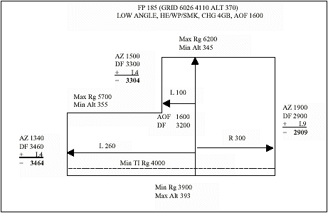
Figure 15-2. Example of a Completed Safety Diagram, HE/WP/SMK
15-7. Computation of Low Angle Safety Data
Use the steps outlined in Table 15-3 and in the matrix in Figure 15-3 as examples for organizing computations. The Low Angle Safety Matrix is used for all munitions except M712 CLGP (Copperhead). Paragraph 15-13 describes M712 safety computations. The data are determined by either graphical or tabular firing tables. In the case of expelling charge munitions, the Safety Table located in the Firing Tables or Firing Table Addendums is utilized to determine Elevation, Time of Flight, Fuze Setting, and Drift. (Note: the Safey Tables used for computing the examples in this chapter are located after the Illum and M825 Low Angle examples). Use artillery expression for all computations except where noted.
Table 15-3: Low Angle Procedures
|
STEP |
ACTION |
|
1 |
On the top third of a blank sheet of paper, construct the basic safety diagram |
|
2 |
In the middle third of the sheet of paper, construct the Low Angle Safety Matrix |
|
3 |
Record the Diagram Ranges from the basic safety diagram. |
|
4 |
Record the Charge from the range safety card. |
|
5 |
Enter the Range Correction, if required. This range correction is only necessary if a nonstandard condition exists and is not already accounted for in a GFT setting, such as correcting for the always heavier than standard White Phosphorous projectile. See figure 2, paragraph (b) to determine range correction. If a range correction is required, it is expressed to the nearest 10 meters. If no range correction is required, enter 0 (zero). |
|
6 |
Determine the Total Range. Total range is the sum of the Diagram Range and the Range Correction. Total Range is expressed to the nearest 10 meters. |
|
7 |
Enter the Range K. Range K is only required if a GFT setting has been obtained but cannot be applied to a GFT (i.e., determining Illumination safety with a HE GFT setting). Range K is simply the Total Range Correction from the GFT setting expressed as a percentage. This percentage, when multiplied by the Total Range, produces the Entry Range. If no GFT setting is available (i.e., pre-occupation safety), then enter 1.0000 as the Range K. If a GFT setting is available, (i.e., post occupation safety), then enter the Range K expressed to four decimal places (i.e., 1.1234). Step 7a demonstrates how to compute Range K. |
|
7a |
Divide Range ~ Adjusted Elevation by the Achieved Range from the GFT setting to determine Range K: Range ~ Adjusted Elevation = Range K, expressed to four decimal places. |
|
8 |
Determine the Entry Range. Multiply the Total Range times Range K to determine the Entry Range. If Range K is 1.0000, then the Entry Range will be identical to the Total Range. Entry Range is expressed to the nearest 10 meters. |
|
9 |
Following the Mini-Max rule, determine the Vertical Interval by subtracting the unit altitude from the altitude corresponding to the Diagram Range, and record it. (Note: Diagram Range is used for computations of VI and Site because this is the actual location of the minimum range line. VI is not computed for minimum time range lines. The Range Correction, Total Range, and Range K are used to compensate for nonstandard conditions, and represent the aimpoint which must be used to cause the round to cross the Diagram Range.) VI is expressed to the nearest whole meter. |
|
10 |
Compute and record Site to the Diagram Range. Use the GST from the head of the projectile family whenever possible. Site is expressed to the nearest whole mil. |
|
11 |
Determine the Elevation from Table C (base ejecting) or TFT/GFT (bursting), and record it. (Note: GFT Settings are not used to determine Elevation, as Range K represents total corrections, and to use a GFT setting would double the effects of those corrections). Elevation is expressed to the nearest whole mil. |
|
12 |
Compute the Quadrant Elevation and record it. Quadrant Elevation is the sum of Elevation and Site. Quadrant Elevation is expressed to the nearest whole mil. |
|
13 |
Determine and record the minimum fuze setting for M564/M565 fuzes. These fuze settings correspond to the Entry Range and are extracted from Table C (base ejecting) or TFT/GFT. (Note: Minimum Fuze Settings are only determined for minimum range lines, and may be computed for separate minimum fuze range lines). Fuze Settings are expressed to the nearest tenth of a fuze setting increment. |
|
14 |
Determine and record the minimum fuze setting for M582/M577 fuzes. These fuze settings correspond to the Entry Range and are extracted from Table C (base ejecting) or TFT/GFT. (Note: Minimum Fuze Settings are only determined for minimum range lines, and may be computed for separate minimum fuze range lines). Fuze Settings are expressed to the nearest tenth of a second. |
|
15 |
Determine and record the Time of Flight corresponding to the entry range from Table C, (base ejecting) or TFT/GFT. Time of Flight is expressed to the nearest tenth of a second. |
|
16 |
Determine the minimum fuze setting for M728/M732 fuzes. Add 5.5 seconds to the time of flight, and express to the next higher whole second. The VT fuze is designed to arm 3.0 seconds before the time set. They have been known to arm up to 5.5 seconds before the time set. That is why this value is added and always expressed up to the next whole second. (Note: Minimum Fuze Settings are only determined for minimum range lines, and may be computed for separate minimum fuze range lines). VT Fuze Settings are expressed up to the next higher whole second. |
|
17 |
Determine and record Drift corresponding to the Entry Range from Table C (base ejecting) or TFT/GFT. Drift is applied to the Basic Safety Diagram by following the "least left, most right" rule. The lowest (least) drift is applied to all left deflection limits, and the highest (greatest) drift is applied to all right deflection limits. Drift is expressed to the nearest whole mil. |
|
18 |
Ensure computations are verified by a second safety-certified person. |
|
19 |
On the bottom third of the sheet of paper, record the data on the safety T. |
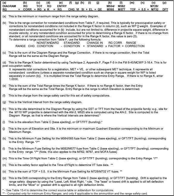
Figure 15-3. Low Angle Safety Matrix
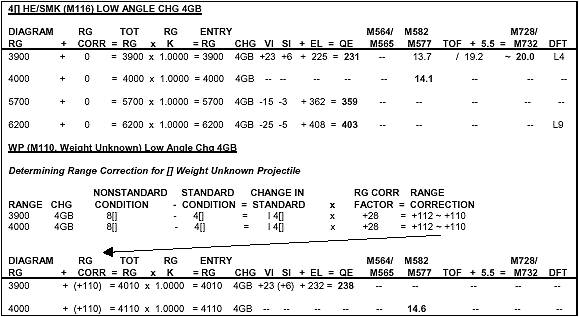
Figure 15-4. Completed Low Angle Safety Matrix, HE/WP/SMK
15-8. Safety T
a. The safety T is a convenient method of arranging safety data and is used to verify the safety of fire commands (Figure 15-5). The information needed by the FDO, XO, or platoon leader, and section chief is organized in an easy to read format. The safety T is labeled with a minimum of firing point location, charge, projectiles(s), fuze(s), angle of fire, and AOL. Other optional entries are subject to unit SOP. Any time new safety data are determined, new safety Ts are constructed and issued only after the old safety Ts have been collected (that is, after a move or after a registration or MET + VE). Use only one charge per Safety T. (Note: The examples in this demonstrate which data is transferred from the Safety Matrix to the Safety Tee. This data is in bold type in the matrix and the associated safety T).
b. It is the FDO's responsibility to ensure that all data transmitted from the FDC is within the limits of the safety T. It is the section chief's responsibility to ensure that all data applied to the ammunition or howitzer is within the limits of the safety T. The FDO must ensure that deflection to fire is between the deflections listed on the safety T. He then must determine if the quadrant elevation corresponding to that deflection is between the minimum and maximum QE on the safety T. Finally, he must ensure that the fuze setting is equal to or greater than the minimum fuze setting listed on the safety T for the specific fuze type.
|
NOTE: A reproducible copy of DA Form 7353-R (Universal Safety T) is included at the end of this manual, in the reproducible forms section. |
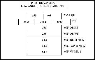
Figure 15-5. Example of a Completed Safety T.
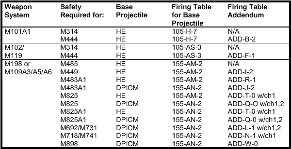
Table 15-4. Tables and Addendums required for Safety Computations
15-9. Updating Safety Data after Determining a GFT Setting
a. After a GFT setting is determined (result of registration or MET + VE technique), the
FDO must compute new safety data. The GFT setting represents all nonstandard conditions in effect at the time the GFT setting was determined (Chapter 10 and 11 discuss Total Corrections in detail). The effect on safety is that the data determined before the GFT setting was determined no longer represent the safety box, and could result in an unsafe condition if not applied to safety computations. In order to update safety, new elevations are determined which correspond to the minimum and maximum ranges. Deflections are modified by applying the GFT deflection correction to each lateral limit. Minimum fuze settings are also recomputed. The basic safety diagram drawn in red on the firing chart does not change. It was drawn on the basis of azimuths and ranges, and it represents the actual limits.
b. There are two techniques which can be used to update safety computations: The
Range K Method and Applying a GFT setting to a GFT. Both methods use the same safety matrices, and apply to both low and high angle fire. The preferred technique for updating safety is to apply a GFT setting to the appropriate GFT. Unfortunately, not all munitions have associated GFTs. Application of Total Corrections is the same as for normal mission processing. The Total Corrections, in the form of a GFT setting or Range K, must be applied in accordance with the data on which they were determined (i.e., the GFT setting for a HE registration applies to all projectiles in the HE family, while a MET + VE for DPICM would apply to all projectiles in the DPICM family). If automation is available a false registration with M795 graze burst data may be used to determine total corrections for all projectiles in the DPICM family (see ST 6-40-2 for procedures). The principle difference between the two techniques is the manner in which minimum fuze setting is determined.
(1) Determining Minimum Fuze Setting with a GFT with a GFT Setting Applied: When a GFT setting is applied and a fuze setting is to be determined, it is extracted opposite the Time Gage Line (if it is the fuze listed on the GFT setting) or as a function of elevation (for all others). Use the procedures in Table 15-5 to update safety using a GFT with a GFT setting applied.
(2) Determining Fuze Setting using the Range K Technique: In order to simplify updating safety, the Range K technique determines all fuze settings as a function of elevation. The difference between registered fuze settings and fuze settings determined using the Range K technique in actual firings and computer simulations varies by only zero to two tenths (0.0 - 0.2) of a Fuze Setting Increment/Second. The safety requirements in the AR 385-63 and incorporation of Minimum Fuze Setting Range Lines adequately compensate for the difference in computational techniques. Figure 15-7 demonstrates how to update safety when no GFT is available, utilizing the Range K technique. Use the procedures in Table 15-3 (Low Angle) or Table 15-8 (High Angle) to update safety using the Range K method.
Table 15-5: Low Angle Procedures using a GFT with GFT Setting applied
|
STEP |
ACTION |
|
1 |
On the top third of a blank sheet of paper, construct the basic safety diagram in accordance with the range safety card. (See Table 15-1 for procedures) |
|
2 |
In the middle third of the sheet of paper, construct the Low Angle Safety Matrix (Figure 1). |
|
3 |
Record the Diagram Ranges from the basic safety diagram. |
|
4 |
Record the Charge from the range safety card. |
|
5 |
Enter the Range Correction, if required. This range correction is only necessary if a nonstandard condition exists which requires a change in aimpoint and is not already accounted for in a GFT setting, such as correcting for the always heavier than standard White Phosphorous projectile. See figure 2, paragraph (b) to determine range correction. If a range correction is required, it is artillery expressed to the nearest 10 meters. If no range correction is required, enter 0 (zero). |
|
6 |
Determine the Total Range. Total range is the sum of the Diagram Range and the Range Correction. Total Range is expressed to the nearest 10 meters. |
|
7 |
Range K. This is not used when determining data with a GFT with a GFT setting applied, as the Elevation Gage line represents Range K. |
|
8 |
Entry Range. This value is the same as the Total Range. Entry Range is artillery expressed to the nearest 10 meters. |
|
9 |
Following the Mini-Max rule, determine the Vertical Interval by subtracting the unit altitude from the altitude corresponding to the Diagram Range, and record it. (Note: Diagram Range is used for computations of VI and Site because this is the actual location of the minimum range line. VI is not determined for minimum fuze range lines. The Range Correction, Total Range, and Range K are used to compensate for nonstandard conditions, and represent the aimpoint which must be used to cause the round to cross the Diagram Range). VI is artillery expressed to the nearest whole meter. |
|
10 |
Compute and record Site to the Diagram Range. Use the GST from the head of the projectile family whenever possible. Site is artillery expressed to the nearest whole mil. |
|
11 |
Place the MHL on the Entry Range and determine the Elevation from the Elevation Gage Line on the GFT and record it. Elevation is artillery expressed to the nearest whole mil. |
|
12 |
Compute the Quadrant Elevation and record it. Quadrant Elevation is the sum of Elevation and Site. Quadrant Elevation is artillery expressed to the nearest whole mil. |
|
13 |
Using the procedures from Appendix G, determine and record the minimum fuze setting for M564/M565 fuzes. These fuze settings correspond to the Entry Range. If the GFT Setting was determined using the M564/M565 fuze, then determine the fuze setting opposite the Time Gage Line. If the GFT setting was not determined using the M564/M565 fuze, then extract the fuze setting corresponding to adjusted elevation. (Note: Minimum Fuze Settings are only determined for minimum range lines, and may be computed for separate minimum fuze range lines). Fuze Settings are artillery expressed to the nearest tenth of a fuze setting increment. |
|
14 |
Using the procedures from Appendix G, determine and record the minimum fuze setting for M582/M577 fuzes. These fuze settings correspond to the Entry Range. If the GFT Setting was determined using the M582/M577 fuze, then determine the fuze setting opposite the Time Gage Line. If the GFT setting was not determined using the M582/M577 fuze, then extract the fuze setting corresponding to adjusted elevation. (Note: Minimum Fuze Settings are only determined for minimum range lines, and may be computed for separate minimum fuze range lines). Fuze Settings are artillery expressed to the nearest tenth of a second. |
|
15 |
Using the procedures from Appendix G, determine and record the Time of Flight corresponding to the Entry Range. Extract the Time of Flight corresponding to adjusted elevation from the TOF scale. Time of Flight is artillery expressed to the nearest tenth of a second. |
|
16 |
Using the procedures in Appendix G, determine the minimum fuze setting for M728/M732 fuzes. Add 5.5 seconds to the time of flight, and express to the next higher whole second. (Note: Minimum Fuze Settings are only determined for minimum range lines, and may be computed for separate minimum fuze range lines). VT Fuze Settings are expressed up to the next higher whole second. |
|
17 |
Determine and record Drift corresponding to adjusted elevation. Drift is applied to the Basic Safety Diagram by following the "least left, most right" rule. The smallest (least) drift is applied to all left deflection limits, and the greatest (most) drift is applied to all right deflection limits. Drift is artillery expressed to the nearest whole mil. |
|
18 |
Ensure computations are verified by a second safety-certified person. |
|
19 |
On the bottom third of the sheet of paper, record the data on the safety T. |

Figure 15-6. Post Occupation Low Angle Safety, Range K Method, HE/WP/SMK
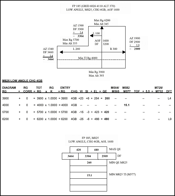
Figure 15-7. Example of Low Angle Safety Shell M825
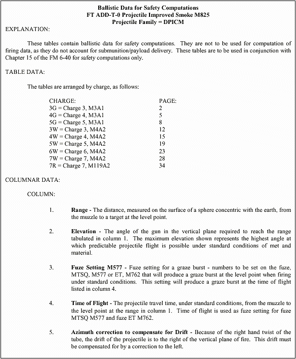
Figure 15-8. Safety Table Data for M825 Example
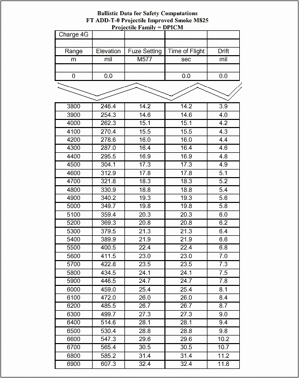
Figure 15-8. Safety Table Data for M825 Example (continued)
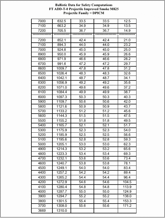
Figure 15-8. Safety Table Data for M825 Example (continued)
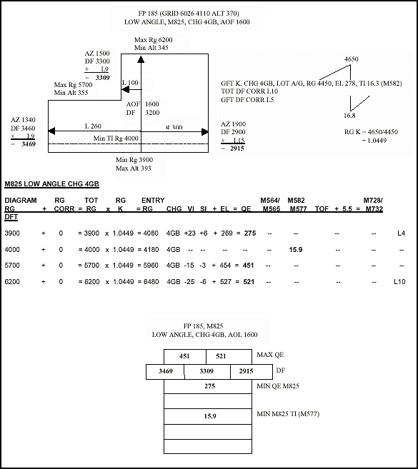
Figure 15-9. Example of Post Occupation Low Angle Safety with Range K applied, Shell M825
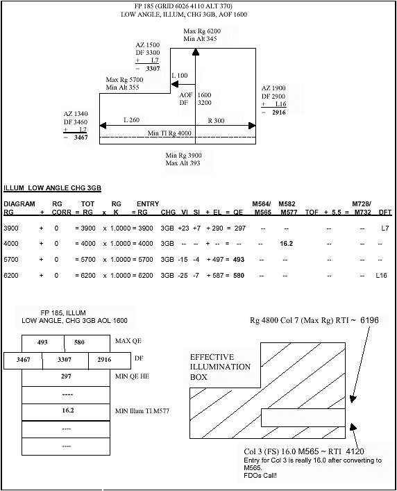
Figure 15-10. Example of Low Angle Safety, Shell Illum
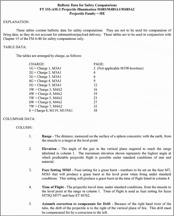
Figure 15-11. Safety Table Data for M485 Illumination Example
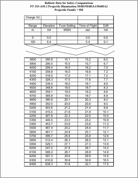
Figure 15-11. Safety Table Data for M485 Illumination Example (continued)
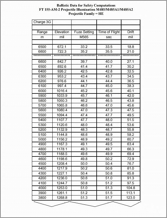
Figure 15-11. Safety Table Data for M485 Illumination Example (continued)
15-10. Determination of Maximum Effective Illumination Area
All illumination safety data are for graze burst. Therefore, when illumination fire mission data are computed, the QE determined includes the appropriate HOB. This will prevent achieving a 600 meter HOB (750 meter HOB for 105 mm) at the minimum and maximum range lines. Before processing illumination fire mission, it is beneficial to determine the maximum effective illumination area for the current range safety card. This area should be plotted on the firing chart to help determine if illumination can be fired and to let the Forward Observers know where they can fire illumination effectively. This area will always be significantly smaller than the HE safety area. See Table 15-6 for steps outlining the general procedure. This area can be increased by computing High Angle data.
|
NOTE: The procedures used to determine the Maximum Effective Illumination Area can be used to for all expelling charge munitions to depict their Maximum Effective Engagement Area. |
Table 15-6. Procedures to Determine Maximum Effective Illumination Area
|
STEP |
ACTION |
|
1 |
Enter the TFT, Part 2, Column 7 (RTI) with the nearest range listed without exceeding the maximum range. |
|
2 |
Determine the corresponding range to target in column 1. This is the maximum range the unit can achieve a 600 meter (155mm) HOB and keep the projectile in the safety box if the fuze fails to function. |
|
3 |
Determine the minimum range for which a 600 meter (155 mm) HOB is achieved and have the fuze function no earlier than the minimum range line. Enter the TFT, Part 2, Column 3, with the nearest listed FS that is not less than the determined minimum FS. Column 3 is the Fuze Setting for the M565 Fuze, so if M577 is to be used, the fuze setting must be corrected by using Table B. Determine the corresponding range to target in Column 1. |
|
4 |
The area between these two lines is the maximum effective illumination area where a 600 meter HOB (155mm) is achieved, the fuze functions no earlier than the minimum range line, and the round does not exceed the maximum range line if the fuze fails to function. Note: High Angle fire produces a much greater effective illumination area. The FDO must use Column 6, Range to Fuze Function, to determine the minimum effective illumination range line. The maximum effective illumination range line is determined by using fuze setting corresponding to Column 7, Range to Impact. |
15-11. Safety Considerations for M549/M549A1 RAP
RAP safety data are computed using the Low Angle Safety or High Angle Safety matrix, as appropriate. The only difference is that a safety buffer must be incorporated for rocket failure or rocket cap burn through. For firing in the Rocket-Off Mode, a 6000 meter buffer must be constructed beyond the maximum range line to preclude the projectile exceeding the maximum range line. For firing in the Rocket-On Mode, a 6000 meter buffer must be constructed short of the minimum range line to preclude the projectile falling short of the minimum range line.
15-12. Safety Considerations for M864 Base Burn DPICM/M795A1 Base Burn HE
Base Burn safety data are computed using the Low Angle Safety or High Angle Safety matrix, as appropriate. The only difference is that a safety buffer must be incorporated for Base Burn Element Failure. A 5000 meter buffer must be constructed short of the minimum range line to preclude the projectile falling short of the minimum range line.
15-13. Safety Procedures for M712 Copperhead
a. Copperhead safety data are determined from ballistic data developed specifically for the Copperhead projectile. Computations are much like those for normal projectiles. The Copperhead round should never be fired with standard data. Therefore, the computation of safety data requires the solving of a Copperhead Met to Target technique for each listed range using the FT 155-AS-1, as covered in Chapter 13, Section 1. See Table 15-7 for steps to compute Copperhead safety. Surface Danger Zones (SDZs) for shell Copperhead are significantly different than normal indirect fire SDZs. AR 385-63 (MCO P3570), chapter 11, contains the SDZs for Copperhead.
b. All ranges listed on the range safety card may not fall within the ranges listed in the TFT charge selection table for that charge and mode. Therefore, additional safety computations may be required for additional charge(s) and mode(s) to adequately cover the impact area. If ranges listed on the range safety card overlap charge and mode range limitations in the charge selection table, then safety for both affected charges and modes must be computed.
Table 15-7. Copperhead Safety Data Procedures
|
STEP |
ACTION |
|
1 |
Construct the basic safety diagram. |
|
2 |
For low angle, circle the lower left hand corner of the safety diagram. Proceed in a clockwise manner, and circle every other corner. For high angle, start in the lower right hand corner and circle every other corner in a clockwise manner. |
|
3 |
Complete a Copperhead Met to Target technique for each circled corner. Record the FS, deflection, and QE in the safety T. The lower left hand corner will provide the minimum FS, maximum left deflection, and minimum QE. The upper right hand corner will provide the maximum right deflection and maximum QE. Intermediate deflections and ranges will provide intermediate deflection limits. |
15-14. Computation of High Angle Safety
a. The safety data for high angle fire is computed in much the same manner as that for low angle fire except for the ballistic variations caused by the high trajectory. Site is computed differently (by using the 10 mil Site Factor and the Angle of Site/10), and mechanical or electronic fuze settings are not determined. (Note: It is the FDO's responsibility to ensure that all High Angle Fuze Settings will cause the fuze to function within the safety box). Table 15-8 contains the steps required for computation of High Angle Safety.
b. Use the steps outlined in Table 15-8 and in the matrix in Figure 15-12 as examples for organizing computations. The High Angle Safety Matrix is used for all munitions except M712 CLGP (Copperhead). The data are determined by either graphical or tabular firing tables. In the case of expelling charge munitions, the Safety Table located in the Firing Tables or Firing Table Addendums is utilized to determine Elevation, Time of Flight, Fuze Setting, and Drift. (Note: The Safety Tables which are used to compute the High Angle examples are located after the Low Angle Safety examples). Use artillery expression for all computations except where noted.
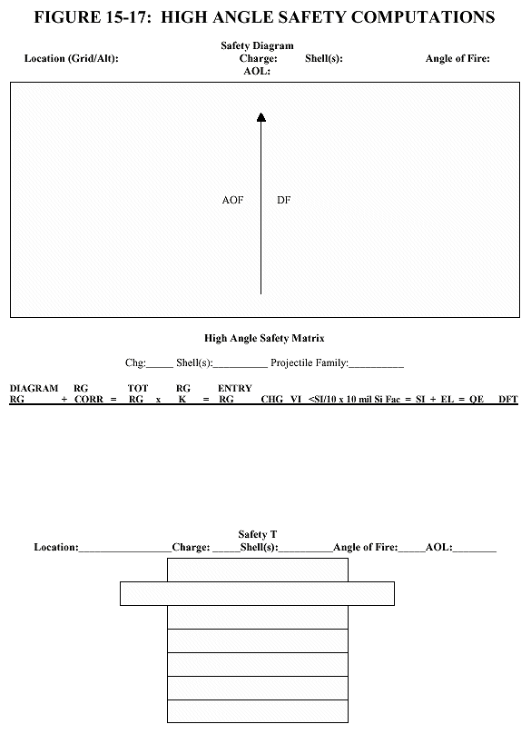
Table 15-8. High Angle Procedures
|
STEP |
ACTION |
|
1 |
On the top third of a blank sheet of paper, construct the basic safety diagram in accordance with the range safety card. (See Table 15-1 for procedures) |
|
2 |
In the middle third of the sheet of paper, construct the High Angle Safety Matrix (Figure 2) |
|
3 |
Record the Diagram Ranges from the basic safety diagram. |
|
4 |
Record the Charge from the range safety card. |
|
5 |
Enter the Range Correction, if required. This range correction is only necessary if a nonstandard condition exists which requires a change in aimpoint and is not already accounted for in a GFT setting, such as correcting for the always heavier than standard White Phosphorous projectile. See figure 2, paragraph (b) to determine range correction. If a range correction is required, it is artillery expressed to the nearest 10 meters. If no range correction is required, enter 0 (zero). |
|
6 |
Determine the Total Range. Total range is the sum of the Diagram Range and the Range Correction. Total Range is expressed to the nearest 10 meters. |
|
7 |
Enter the Range K. Range K is only required if a GFT setting has been obtained but cannot be applied to a GFT (i.e., determining Illumination safety with a HE GFT setting). Range K is simply the Total Range Correction from the GFT setting expressed as a percentage. This percentage, when multiplied by the Total Range, produces the Entry Range. If no GFT setting is available (i.e., pre-occupation safety), then enter 1.000 as the Range K. If a GFT setting is available, (i.e., post occupation safety), then enter the Range K expressed to four decimal places (i.e., 1.1234). Step 7a demonstrates how to compute Range K. |
|
7a |
Divide Range ~ Adjusted Elevation by the Achieved Range from the GFT setting to determine Range K: Range ~ Adjusted Elevation = Range K, expressed to four decimal places. |
|
8 |
Determine the Entry Range. Multiply the Total Range times Range K to determine the Entry Range. If Range K is 1.0000, then the Entry Range will be identical to the Total Range. Entry Range is artillery expressed to the nearest 10 meters. |
|
9 |
Following the Mini-Max rule, determine the Vertical Interval by subtracting the unit altitude from the altitude corresponding to the Diagram Range, and record it. (Note: Diagram Range is used for computations of VI and Site because this is the actual location of the minimum range line. The Range Correction, Total Range, and Range K are used to compensate for nonstandard conditions, and represent the aimpoint which must be used to cause the round to cross the Diagram Range). VI is artillery expressed to the nearest whole meter. |
|
10 |
Determine and record the Angle of Site divided by 10 to the Diagram Range. This is performed by dividing the Angle of Site (use the appropriate GST, if possible) by 10. <SI/10 is artillery expressed to the nearest tenth of a mil, and has the same sign as the VI. |
|
11 |
Determine and record the 10 mil Site Factor from the GFT or TFT which heads the projectile family. (Note: Remember to use the Diagram Range to compute 10 mil Si Fac). 10 mil Si Fac is artillery expressed to the nearest tenth of a mil and is always negative. |
|
12 |
Compute and record Site. Site is the product of <SI/10 times 10 mil Si Fac. Site is artillery expressed to the nearest whole mil. |
|
13 |
Determine the Elevation from Table C (base ejecting) or TFT/GFT (bursting), and record it. (Note: GFT Settings are not used to determine Elevation, as Range K represents total corrections, and to use a GFT setting would double the effects of those corrections). Elevation is artillery expressed to the nearest whole mil. |
|
14 |
Compute the Quadrant Elevation and record it. Quadrant Elevation is the sum of Elevation and Site. Quadrant Elevation is artillery expressed to the nearest whole mil. |
|
15 |
Determine and record Drift corresponding to the Entry Range from Table C (base ejecting) or TFT/GFT. Drift is applied to the Basic Safety Diagram by following the "left least, right most" rule. The lowest (least) drift is applied to all left deflection limits, and the highest (greatest) drift is applied to all right deflection limits. Drift is artillery expressed to the nearest whole mil. |
|
16 |
Ensure computations are verified by a second safety-certified person. |
|
17 |
On the bottom third of the sheet of paper, record the data on the safety T. |
|
Note: Minimum fuze settings are not computed for High Angle safety. It is the FDO's responsibility to ensure that all fuze settings will cause the projectile to function in the impact area. |
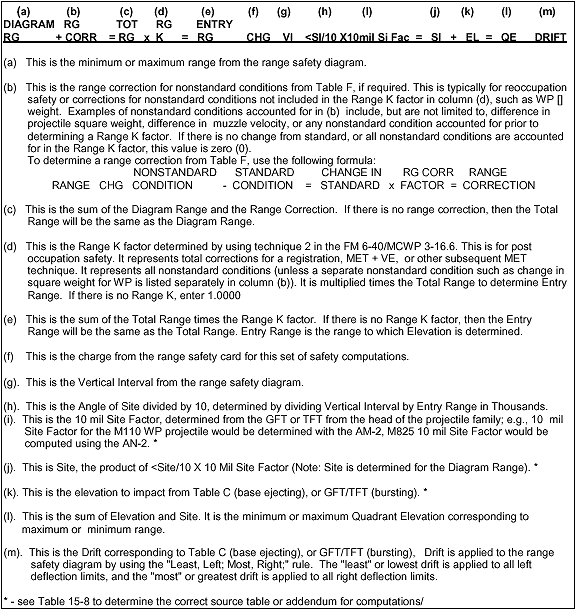
Figure 15-12. High Angle Safety Matrix
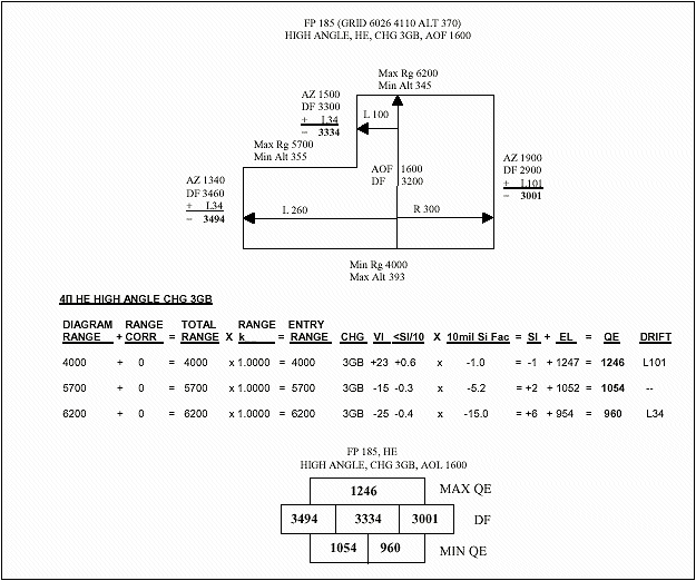
Figure 15-13. Example of High Angle Safety, Shell HE
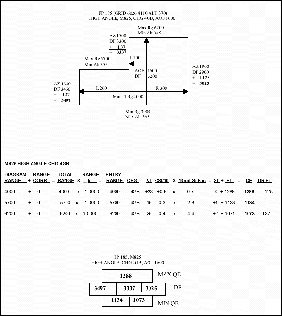
Figure 15-14. Example of High Angle Safety, Shell M825
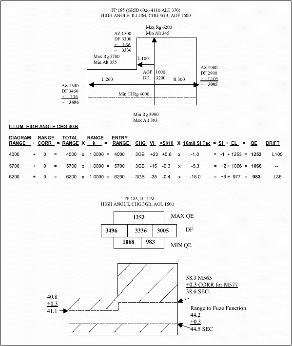
Figure 15-15. Example of High Angle Safety, Shell Illum

Section III
Minimum Quadrant Elevation
The XO or platoon leader is responsible for determining the lowest QE that can be safely fired from his position that will ensure projectiles clear all visible crests (minimum QE).
15-15. Elements of Computation
A minimum quadrant for EACH howitzer is ALWAYS determined. The maximum of these minimum quadrants is the XO's minimum quadrant. Use of the rapid fire tables in ST 6-50-20 is the fastest method of computing minimum QE. The QE determined from ST 6-50-20 is always equal to or greater than (more safe) than manual computations. Manual computations are more accurate than the rapid fire tables and are used if the sum of the site to crest and the angle needed for a 5-meter vertical clearance is greater than 300 mils. Figure 15-18 shows the elements of minimum QE.
a. Piece-to-crest range (PCR) is the horizontal distance between the piece and the crest, expressed to the nearest 100 meters. Procedures for measurement are discussed in paragraph 15-16.
|
NOTE: All angles are determined and expressed to the next higher mil. |
b. Angle 1 (Figure 15-18) is the angle of site to crest measured by the weapons. See paragraph 15-16 for procedures.
c. Angle 2 (Figure 15-18) is the vertical angle required to clear the top of the crest. For quick, time, and unarmed proximity (VT) fuzes, a vertical clearance of 5 meters is used. For armed VT fuzes, see paragraph 15-19.
d. Angle 3 (Figure 15-18) is the complementary angle of site. It is the complementary site factor (TFT, Table G) for the appropriate charge at the piece to crest range mulitiplied by the sum of angles 1 and 2. Site is the sum of angles 1, 2, and 3.
|
NOTE: The entry argument for Table G is PCR. If it is not listed, do not interpolate, use the next higher listed value. |
e. Angle 4 (Figure 15-18) is the elevation (TFT, Table F) for the appropriate charge corresponding to the PCR.
f. Angle 5 (Figure 15-18) is a safety factor equivalent to the value of 2 forks (TFT, Table F) for the appropriate charge at the PCR.
g. The sum of angles 1 through 5 (Figure 15-18) is the minimum QE for the weapon and the charge computed.
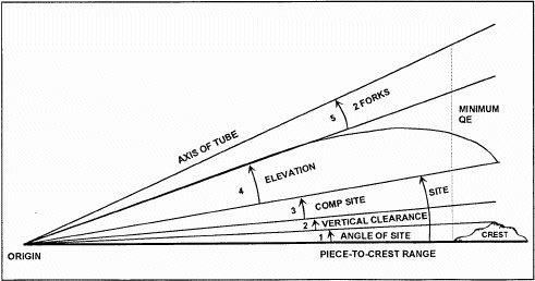
Figure 15-18. Angles of Minimum QE
15-16. Measuring Angle of Site to Crest
As soon as the piece is "safed", prefire checks conducted, and ammunition prepared , position improvement begins with verification of site to crest as measured by the advance party. The advance party measures site to crest with an M2 compass or aiming circle. The section chief measures the angle of site to crest and reports it to the XO or platoon leader. To measure the angle of site to crest, the section chief sights along the bottom edge of the bore, has the tube traversed across the probable field of fire, and has the tube elevated until the line of sight clears the crest at the highest point. He then centers all bubbles on the elevation mount and reads the angle of site to the crest from the elevation counter. This angle of site and the PCR are reported as part of the section chief's report.
15-17. Measuring Piece-To-Crest Range
a.
(1) Taping. This is the most accurate method; however, it is normally too time-consuming.
(2) Subtense. This method is fast and accurate.
(3) Map Measurement. This method is fast and accurate if the obstacle can be accurately located (for example, a lone tree will not appear on a map).
(4) Pacing. This method is time-consuming and depends on the distance and accessibility to the crest.
(5) Estimation. This method is least accurate, but it is used when other methods are not feasible.
b. Regarless of the method used to measure PCR, the XO or platoon leader must verify PCR before he computes QE. He can do this by using any of the five methods.
15-18. Computation of Fuzes Other Than Armed VT
a. The XO or platoon leader does the computations indicated in this section if the sum of angles 1 and 2 (Figure 15-18) exceeds 300 mils or if the rapid firing tables (RFTs) are not available. All angles are determined and expressed to the next higher mil. Table 15-9 lists the steps and solves an example of an XO's or platoon leader's manual computations.
Table 15-9. Manual Minimum QE Computations.
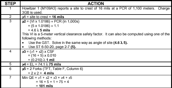
b. The same example is solved in Table 15-10 by using RFTs in the ST 6-50-20, Appendix B.
Table 15-10. RFT Minimum QE Computations.

c. One howitzer section may report a site to crest that is unusually high. If the XO or platoon leader determines that it is the result of a single narrow obstruction (such as a tree), the piece can be called out of action when firing a deflection that would engage the obstruction. This would enable the platoon to use the next lower site to crest. Other alternatives are to remove the obstruction or move the weapon.
d. Table 15-11 illustrates why minimum QE is computed for all guns, regardless of which has the largest site to crest.
Table 15-11. RFT Example for Howitzer Platoon.

15-19. Computations for Armed VT Fuze (Low-Angle Fire)
a. The method of computing the XO's minimum QE for firing a projectile fuzed with an M728 or M732 fuze depends on the method in which the fuze is used. The proximity (VT) fuze is designed to arm 3 seconds before the time set on the fuze; however, some VT fuzes have armed as early as 5.5 seconds before the time set on the fuze. Because of the probability of premature arming, a safety factor of 5.5 seconds is added to the time of flight to the PCR. Since time on the setting ring is set to the whole second, the time determined in computing minimum safe time is expressed up to the nearest whole second. A VT fuze is designed so that it will not arm earlier than 2 seconds into its time of flight, which makes it a bore-safe fuze.
b. In noncombat situations, the XO or platoon leader determines the minimum safe time by adding 5.5 seconds to the time of flight to the minimum range line as shown on the range safety card. The minimum QE determined for fuzes quick and time is also valid for fuze VT.
c. In combat situations, the XO or platoon leader determines the minimum QE and a minimum safe time for fuze VT. The minimum QE determined for PD fuzes is safe for VT fuzes if the fuze setting to be fired equals or is greater than the minimum safe time determined in paragraph a above. If the XO or platoon leader finds it necessary to fire a VT fuze with a time less than the minimum safe time, he must modify the minimum QE. He does this by increasing the vertical clearance to ensure that the fuze will not function as it passes over the crest. In addition, he must ensure the fuze will not function over any intervening crests along the gun-target line (See paragraph 15-21).
d. If the projectile is to be fired with the VT fuze set at a time less than the minimum safe time, allowance must be made for vertical clearance of the crest. Vertical crest clearances for armed M728 and M732 VT fuzes fired over ordinary terrain for all howitzer systems is 70 meters.
e. If the projectile is to be fired over marshy or wet terrain, the average height of burst will increase. The vertical clearance is increased to 105 meters. If the projectile is fired over water, snow, or ice, the vertical clearance is 140 meters.
f. The minimum QE for armed fuze VT when a fuze setting less than the minimum safe time is fired is based on the piece-to-crest range and a vertical clearance as indicated in paragraphs d and e above.
g. Figure 15-19 shows a decision tree for application of armed VT minimum QE.
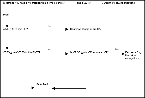
Figure 15-19. Armed VT Decision Tree.
h. Table 15-12 is an example of computations to determine minimum QE for an armed VT fuze.
Table 15-12. Manual Armed VT Minimum QE Computations.

i. The same example is solved in Table 15-13 by using the RFT in the ST 6-50-20, Appendix A.
Table 15-13 RFT Minimum QE Computations.
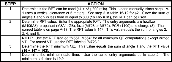
j. If the VT fuze setting to be fired is equal to or greater than the minimum safe VT time, the minimum QE for fuzes quick and time applies. If the VT fuze setting to be fired is less than the minimum safe VT time, the minimum QE determined for armed VT applies.
15-20. Using Minimum Quadrant Elevation
After computing minimum QE for each charge authorized, the XO or platoon leader must compare the minimum QE to the QE required to clear the minimum range line. The XO must then select the highest quadrant for each charge to be used as the minimum QE to be fired from that position.
15-21. Intervening Crest
(1) Determine firing data to the crest (include all nonstandard conditions) and add 2 forks (Table 15-12).
(2) Determine a minimum QE in a similar manner as XO's minimum QE (Table 15-13).
(3) Use the trajectory tables in the appendix of the TFT.
b. Option 1 is preferred because it incorporates all current nonstandard conditions that will affect the projectile along the trajectory. The FDO has the responsibility to determine on the basis of availability of corrections for nonstandard conditions if this really is the best option. Table 15-12 lists the steps.
Table 15-14. Intervening Crest, Option 1.
|
STEP |
ACTION |
|
1 |
Upon occupation, the FDO analyzes the terrain for intervening crests. |
|
2 |
Upon determining the altitude of this crest, he computes firing data to this point (QE). The best solution includes all available corrections for nonstandard conditions (current and valid GFT setting). |
|
3 |
Add the value of 2 forks (TFT, Table F, Column 6) to the QE determined in step 2 to ensure that round-to-round variations (probable errors) will clear the crest. |
|
4 |
The FDO then records this QE and charge on his situation map as a check to ensure that rounds will clear the intervening crest. |
|
5 |
Upon receipt of a fire mission, the FDO will compare his intervening crest QE to his fire mission quadrant. One of the three following situations will occur: 1) The target is located short of the intervening crest. The FDO does not consider the effects of the crest at this time. 2) The mission QE exceeds intervening crest QE by a significant margin, indicating the rounds will clear the crest. 3) Fire mission QE exceeds intervening crest QE by only a small margin or is less than intervening crest QE, indicating the round may or may not clear the crest. The FDO must determine if the round will clear after considering the following: |
Table 15-14. Intervening Crest, Option 1 (Continued).
|
STEP |
ACTION |
Upon realizing that the round may not or will not clear the crest, the FDO can either fire high angle or a reduced charge. The quickest choice would be to fire high angle, but tactical situations may prevent this. Firing a lower charge will increase dispersion more than high angle. For example, at a range of 6,000 meters, the following applies:
If a lower charge is selected, steps 2 through 5 must be repeated. |
|
|
6 |
If VT fuzes are to be fired (M700 series), the FDO must take additional steps to ensure that the VT fuze does not arm before passing over the crest. Follow the steps for determining armed VT minimum QE and FS in paragraph 15-15. |
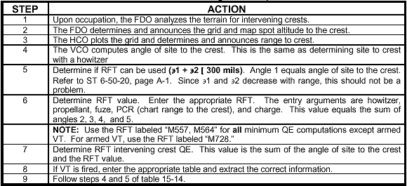
c. Option 2 does not include current conditions for all nonstandard conditions. Table 15-15 lists the steps.
Table 15-15. Intervening Crest, Option 2.
d. The least preferred option is using the trajectory charts in the appendix of the TFT. This offers a quicker but less accurate method to clear the intervening crest since it is based off of standard conditions. The FDO must make a judgment call when to use these charts. The FDO must use caution when making this decision.
|
NEWSLETTER
|
| Join the GlobalSecurity.org mailing list |
|
|
|

