Chapter 13
SPECIAL MUNITIONS
This chapter describes procedures for special munition employment. Appendix H provides further information on special mission processing.
Section I
Copperhead
The cannon-launched guided projectile (CLGP) M712 (Copperhead) is a 155-mm, separate-loading, laser-guided, HE projectile. It is heavier (137.6 pounds) and longer (54 inches) than the standard 155-mm projectile. The M712 projectile consists of three main sections: a guidance section (forward), warhead section (center), and control section (rear). The guidance section contains the seeker head assembly and the electronics assembly. The nose of the projectile houses a laser seeker in a plastic cone. The warhead section contains an HE antitank warhead consisting of 14.75 pounds of composition B. The control section includes the fins and wings that deploy in flight and allow the round limited maneuverability.
13-1. Description
a. The Copperhead projectile is shipped and stored in a sealed container. The projectile requires no assembly or testing at the firing site.
b. The FDC can compute firing data for shell Copperhead by using either a shaped trajectory or a ballistic trajectory.
|
NOTE: The shaped trajectory is based on a revised targeting logic that was first introduced with FT 155-AS-0 (Rev 1) and continued with FT 155-AS-1. The change essentially results in firing higher charges at lower quadrant elevations, resulting in flatter trajectories. This was done to maximize the employment of Copperhead projectiles under low cloud ceilings. Many of the tables in FT 155-AS-1 refer to ballistic or "glide" mode (for example, Table F). In this current FT, the terms glide and shaped are used synonymously, even though they are different trajectories. A true glide mode is only achieved when computing data by using FT 155-AS-0. However, this method is not recommended because it will produce poor results under low cloud ceilings. |
(1) The trajectory of the Copperhead projectile is similar to that of a conventional round. Only when the projectile reaches a point on the descending branch of the trajectory does it differ. At that point, on the basis of the two-digit timer setting included in the fire commands, the guidance and control systems are activated. This enables the projectile to alter the remainder of its trajectory.
(2) At 20 seconds from impact, the FDC cues the laser designator operator, who begins designating the target. The ground laser operator may use a G/VLLD, a laser target designator (LTD), or modular universal laser equipment (MULE). Airborne systems include the AH-64, OH-58D, and unmanned aerial vehicles. The Copperhead projectile acquires the reflected laser energy and initiates internal guidance and control, allowing it to maneuver to the target. If the time of flight of the projectile is less than 20 seconds, the FDC will inform the observer to designate the target concurrent with the shot message (that is, LASER ON, SHOT, OVER).
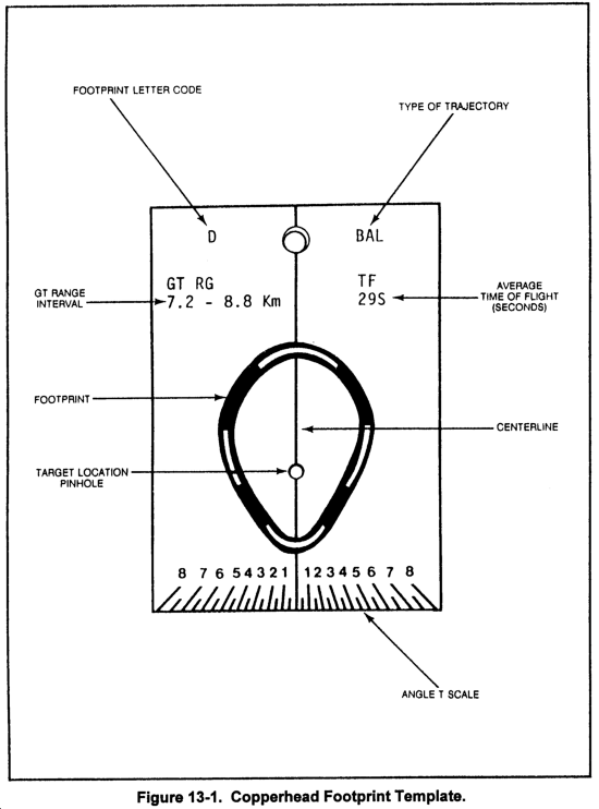
c. The ground surface area in which the round can maneuver is limited. The optimum limits of maneuverability of the Copperhead round is called a footprint (Figure 13-1). The size of the footprint is determined by the GT range and the shape of the trajectory, but it can also be affected by cloud height. The ballistic aimpoint is on the GT line, usually short of the target location sent by the laser designator operator. The distance that the ballistic aimpoint is short of the target location varies and is called the offset correction. This offset distance is used to ensure that the maximum probability of hit occurs at the original target location sent by the observer. The larger the target location error, the lower the probability of hitting the target.
d. Copperhead missions, like conventional missions, can be fired on either planned targets or targets of opportunity. Planned targets are priority targets or on-call targets.
(1) Because of its relatively short response time, the Copperhead planned target is the preferred method for employing Copperhead. Unless otherwise specified on the target list, two Copperhead rounds are prepared in advance for each Copperhead priority target. DA Form 5711-R (Copperhead Planned Target List Work Sheet) may be used to quickly update data for planned Copperhead targets. These data can then be transferred to DA Form 4504 when the mission is fired. Figure 13-2 shows an example Copperhead planned target list work sheet.
|
NOTE: A reproducible copy of DA Form 5711-R is provided at the back of this publication. |
(2) On-call target procedures for Copperhead are the same as those for conventional on-call missions.
|
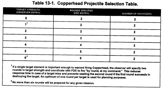
NOTE: FDC personnel must ensure that at least two howitzers and two Copperhead rounds are prepared for any mission. This action increases firing unit responsiveness if a round or howitzer malfunctions. The criteria in Table 13-1 are used for all Copperhead missions. |
13-2. Computations for Shell Copperhead
a. When a target list is received from the battalion FDC, Copperhead priority targets are processed first. Battery or platoon FDC personnel must know how to use the Copperhead footprint templates and must be aware of the maximum 800-mil angle T requirement. Priority target firing data usually are sent to two adjacent howitzers. The FDC transmits the message to observer and informs the observer when the unit is prepared to fire the priority target. Response time is excessive if the Copperhead rounds and the howitzers are not prepared in advance. Firing data for the rest of the targets on the target list are then computed and recorded by target number in the FDC.
b. As the situation changes, recomputation may be required and is done by the FDC.
13-3. Copperhead SOP
a. Unit SOPs dealing with Copperhead (Cphd) missions are helpful in rapidly disseminating mission-essential information with a minimum of discussion. When used with extensive training, a unit SOP can result in more responsive fires.
(1) An observer requesting Copperhead fires on planned targets and targets of opportunity will send a call for fire to the battery or platoon FDC over an established fire net.
(2) The standard target list is used to initiate a planned target.
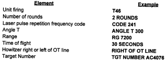
(3) To fire on a planned target, the observer transmits a call for fire that includes the following elements:
(4) To enhance mission responsiveness when engaging priority targets, the observer may omit the target description, method of engagement, and method of control; for example, T46 THIS IS T18, FIRE TARGET AB2213, OVER.
(5) If the number of rounds to be fired is not specified in the call for fire, the FDC will fire the number of rounds specified for that target on the Copperhead target list. If the number of rounds is not specified on the target list, the FDC will fire one round at the target and direct the howitzer(s) to prepare, but DO NOT LOAD, a second round. The MTO will reflect 1 round.
(6) When the observer requests AT MY COMMAND, the Copperhead rounds will be freed at intervals of at least 30 seconds when the observer gives the initial command to fire. When BY ROUND AT MY COMMAND is requested, the observer will control the firing of each Copperhead round. The observer must understand this and act accordingly so as not to waste rounds.
b. For targets of opportunity, the call for fire includes the following elements:
|
NOTE: For a target of opportunity, the call for fire must specify Copperhead. |
13-4. Message to Observer
a. After a call for fire is processed, an MTO is sent as soon as possible before firing.
b. The MTO for Copperhead missions includes the following elements:
c. For a Copperhead mission to be successful, the three-digit pulse repetition frequency (PRF) code set on the Copperhead round must match the PRF code set on the observer's designator. The FDC should have a list of all observer PRF codes by call sign. The FDC selects the proper PRF code on the basis of the identification of the observer sending the call for fire. The PRF code is then sent to the howitzers in the fire commands and is placed on the Copperhead round. The observer verifies the PRF code announced in the MTO.
13-5. Fire Order
The elements established as standard are not addressed unless a change in the standard is desired. Two howitzers will support a given Copperhead fire mission.
13-6. Computation of Firing Data
| NOTE: FT 155-AS-1 is used to compute firing data for Copperhead. There are no GFTs for FT 155-AS-1. FT 155-AS-1 supersedes FT 155-AS-0 (Rev 1) firing tables. |
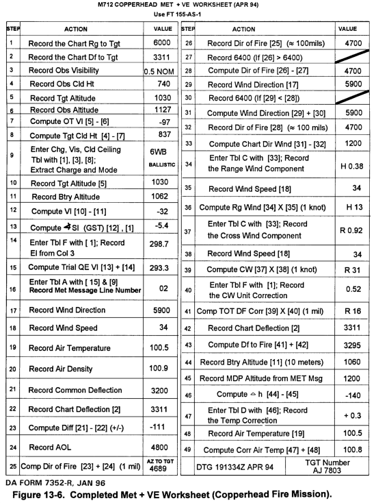
a. Initial Chart Data. The computation of firing data for Copperhead begins with the determination of chart data. This applies to both planned targets (target locations taken from the Copperhead target list) and targets of opportunity (target location provided in the call for fire). The initial chart data required for Copperhead missions is chart range, chart deflection, and angle T. Chart data are determined and announced by the HCO.
b. Trajectory and Charge Selection. Given the chart range to the target, observer visibility, and target cloud height, the FDO enters the Copperhead charge selection table in the Copperhead TFT. Determine the charge to fire by entering the table with the visibility followed by cloud height. Identify the range interval that includes the chart range. To determine the visibility and cloud height to use, see the table on page xxx in the introduction of the TFT. For example, for an M109A3 unit with nominal visibility, cloud height of 900, and chart range of 6300, the unit would use the ballistic mode and fire charge 6 white bag.
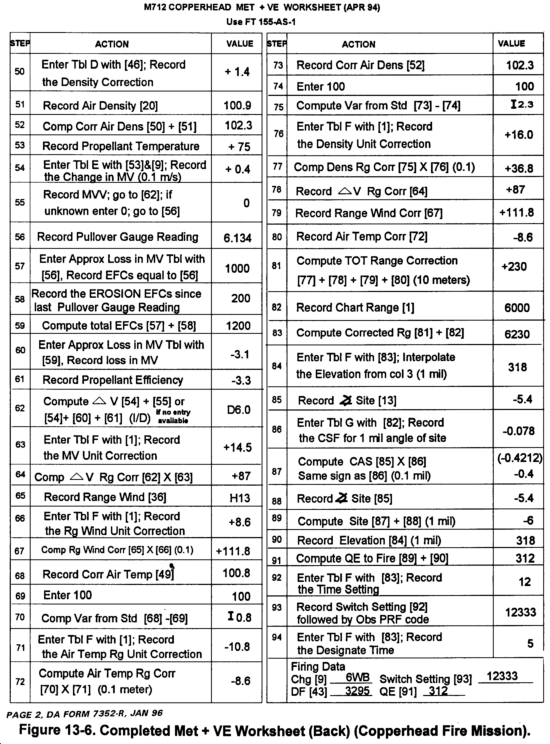
c. Computations. Met corrections have a large impact on the Copperhead projectile; therefore, firing data should not be determined without compensating for nonstandard conditions.
(1) Priority or planned targets. Firing data for planned targets is based on the solving of a met to target with the AS-1 TFT.
(2) Targets of opportunity. Because of the decreased response time for targets of opportunity, solving a met to a target is not practical. The following procedures can be used to determine firing data for targets of opportunity.
(a) FDO selects charge(s) to cover area of operations. FDO must also consider expected visibility and cloud height.
(b) Solve a met + VE for selected charge(s) by using the center range of the range interval for the charge(s).
(c) Use the total range correction determined as a "range K" to be applied to other missions with that charge.
(d) When the observer requests a Copperhead target of opportunity, apply the range K to the chart range to determine the entry argument for Table F, Column 1.
(3) Manual met to target. The following guidelines apply when a met to target for Copperhead is solved manually:
(a) Use a position deflection correction of zero.
(b) Use MVV calibration data determined from the M90 velocimeter and corrected for nonstandard conditions as the velocity error.
|
NOTE: In most situations, an MVV for shell Copperhead will be unavailable. The loss in muzzle velocity due to tube erosion (as determined from a recent pullover gauge reading and/or from EFC rounds) can be used as the position VE. Be sure to use the AS-1 TFT to determine an estimated loss in MV base on the current pullover gauge reading. Refer to Chapter 4 for further information on predictive MVV techniques. |
(c) No fuze setting correction is determined.
13-7. Angle T and Target Cloud Height Checks
a. The FDO makes the angle T check by listening to the announced angle T and determining if it meets the angle T requirement for Copperhead (800 mils or less). Copperhead should not be fired when the angle T is greater than 800 mils. An angle T of this magnitude may seriously degrade the ability of the round to successfully acquire and engage its intended target. The FDO should also check the observer location to ensure he is not located "long" along the GT line. If this were the situation, the Copperhead projectile may not be able to seek the reflected laser energy.
b. Depending on the method used to locate the target, the target cloud height can be computed in one of two ways.
(1) If the target is located by grid coordinates, subtract the OT VI from the observer cloud height to determine the target cloud height.
(2) If the target is located by laser polar plot, as targets of opportunity normally are, compute the target cloud height as follows: First, use the OT distance and the VA reportedly the observer to compute the OT VI with the C and D scales of the GST. Then subtract the OT VI from the observer cloud height to determine the target cloud height.
c. The VCO computes the target cloud height and reports it to the FDO. The FDO enters the table with the target cloud height to determine the cloud ceiling.
d. An OT vertical interval of less than 30 meters can be ignored for targets of opportunity. In such cases, target cloud height equals observer cloud height.
e. Insufficient target cloud height will adversely affect the accuracy of the Copperhead round.
13-8. Trajectories
a. The Copperhead projectile travels in a trajectory determined by the switch setting applied. The trajectory used is dependent on the chart range to the target observer visibility, and target cloud height. The targeting logic used in the FT 155-AS-1 allows the FDC to select from one of two trajectories--ballistic or shaped.
b. The ballistic trajectory has a greater angle of fall, resulting in greater target area effects. In the ballistic mode, the projectile travels in a ballistic trajectory. This trajectory is only affected near the end of the descending branch when the projectile acquires and homes in on the reflected laser energy. If the projectile fails to acquire the designator, the projectile would continue to follow the ballistic trajectory to the ballistic aimpoint. The ballistic aimpoint is the point to which the fining data are computed, usually offset along the GT line by 0 to 500 meters.
c. The angle of fall generated by the ballistic solution is so steep as to limit the time that the projectile has, after exiting the cloud cover, to acquire the laser energy. The shaped trajectory allows the projectile to approach the target at a shallow angle and thus stay below cloud cover. The projectile may be caused to glide at a constant angle in the descending branch of the trajectory, allowing longer exposure of the projectile to the reflected laser energy and thereby enhancing acquisition probability. (See Figure 13-3.)
13-9. Switch Setting
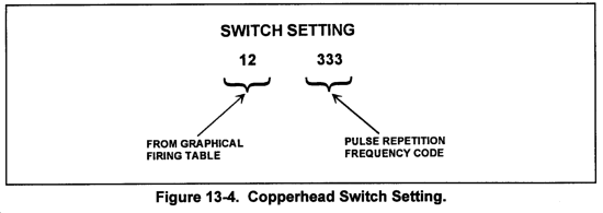
The Copperhead switch setting consists of five digits. (See Figure 13-4.) The first two numbers are the time setting determined by the FDC. The first digit programs the projectile for a specific trajectory. A first digit of 1 or 2 results in a ballistic trajectory, while a first digit of 3 through 8 results in a shaped trajectory. The second digit programs a time delay based on the duration of flight and type of trajectory. The program delay digits of 1 through 8 will result in a delay of 0 to 45 seconds for the ballistic mode and 0 to 48 seconds for the shaped trajectory. After the time delay has expired, the main portion of the battery will activate, providing power to the electronic circuits and deploying the wings. The last three digits are the PRF code for the G/VLLD or MULE operator. This setting establishes a common laser frequency between the projectile and the G/VLLD or MULE.
13-10. Computing Site
The VCO manually computes site for Copperhead by using the ballistic aimpoint.
13-11. Computing Deflection Correction
The Copperhead round has no correction for drift. Therefore, the total deflection correction equals the GFT deflection correction and is applied without modification throughout that charge and mode.
13-12. Limits of the Base Piece Solution
a. Firing data for Copperhead is initially computed from the base piece location. If the center of the two howitzers firing the Copperhead mission is within 100 meters of the base piece, the firing data computed at the base piece may be used. If the two howitzers are located father than 100 meters from the base piece, deflection and elevation corrections from the two-howitzer subelement should be computed and applied to the base piece solution.
b. When time for computing data is limited, as is normally the case for targets of opportunity, and the two howitzers are located further than 100 meters from the base piece, the FDC should compute at least a deflection correction. The Copperhead round can compensate for errors in range easier than it can for errors in deflection.
13-13. Target Attack Contingencies
a. If the Copperhead round cannot be fired on a target because of insufficient target cloud height, the FDC must inform the observer requesting the mission. Coordination between the observer and the FDC can then be made to fire other types of munitions on the target.
b. If the Copperhead round cannot be fired on a target because the angle T is greater than 800 mils, the battery or platoon FDC should contact the battalion FDC to see if the mission can be taken by another unit having an angle T of 800 mils or less. If another unit is available, the original battery or platoon FDC tells the observer to contact the FDC of the unit taking the mission. If no other units are available, the observer and the FDC can coordinate to fire other types of munitions on the target.
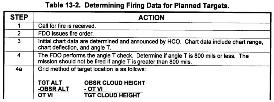
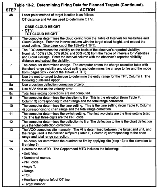
c. The steps in Table 13-2 are used to determine firing data for planned targets.
|
NOTE: Receipt of the Copperhead MTO by the observer indicates that the unit is ready to fire. |
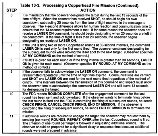
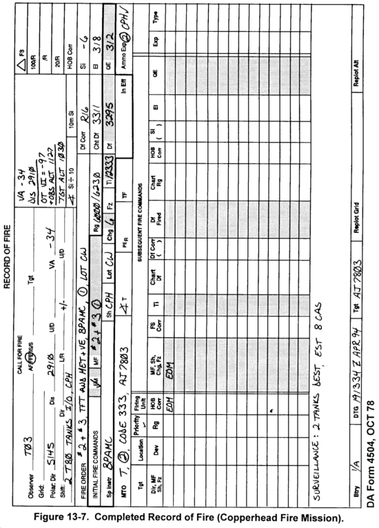
d. The steps in Table 13-3 are used to process a Copperhead mission with a record of fire.
|
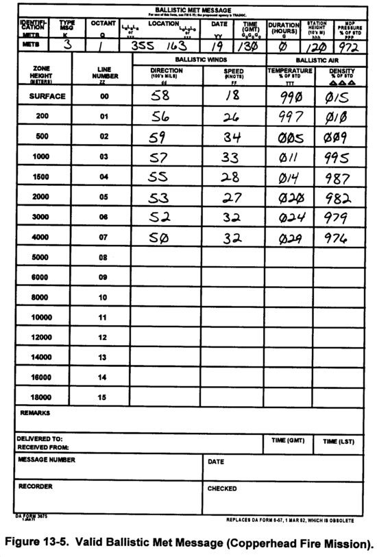
NOTE: Figures 13-5 through 13-7 show a completed Copperhead fire mission using the 155-AS-1 TFT. The Met + VE Worksheet (DA Form 7352-R) is a new reproducible form located at the back of this book. |
Section II
ROCKET-ASSISTED PROJECTILE
Rocket-assisted projectiles are available for the 105-mm and 155-mm howitzers. They are designed to extend the range of the howitzers. The basic rocket-assisted projectiles are filled with HE material. They produce blast and fragmentation in the target area. Computation procedures for the two basic HE RAPs are identical. Firing tables are available for the rocket on mode only.
13-15. Description
a. The 105-mm RAPs are the M548 and M913. The 155-mm projectiles are the M549 and M549A1. For the M109A2/A3 weapons, these projectiles are fired with charges 7 (M4A2), 8 (M119A1), and 7 (M119A2). The M198 howitzers may use charges 7 (M4A2), 8 (M119A1), 7 (M119A2), and 8S (M203 only for the M549A1 projectile).
b. Rocket-assisted projectiles should always be fired by using current GFT settings because most RAP missions are expected to be FFE missions. The multiplot GFT setting is recommended for use with RAP. When no RAP registration data are available, a met-to-target technique should be solved by using MV data, propellant temperature, and rocket motor temperature (assumed to be the same as the propellant temperature).
13-16. Manual Computations
a. Procedures for computing HE RAP firing data are identical to those for conventional HE rounds. The RAP GFTs and GSTs are similar to and are read in the same way as those for conventional HE rounds with two exceptions. The 155-mmM549A1 GFT has no fuze setting scale.
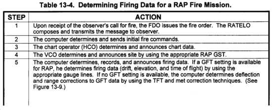
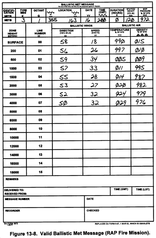
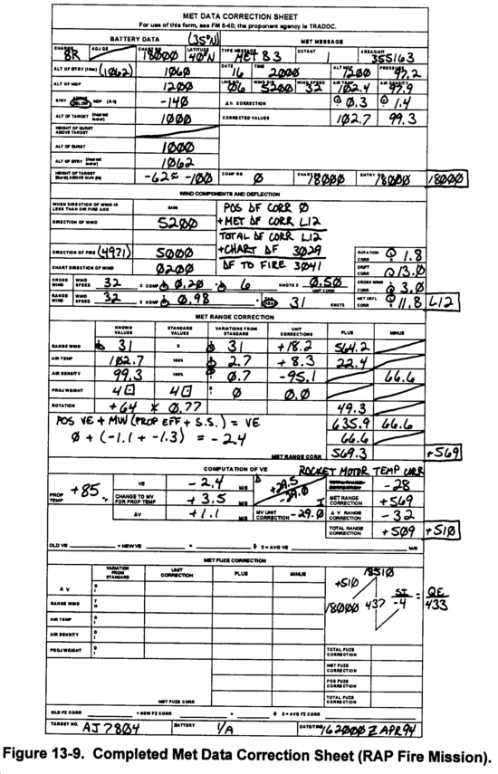
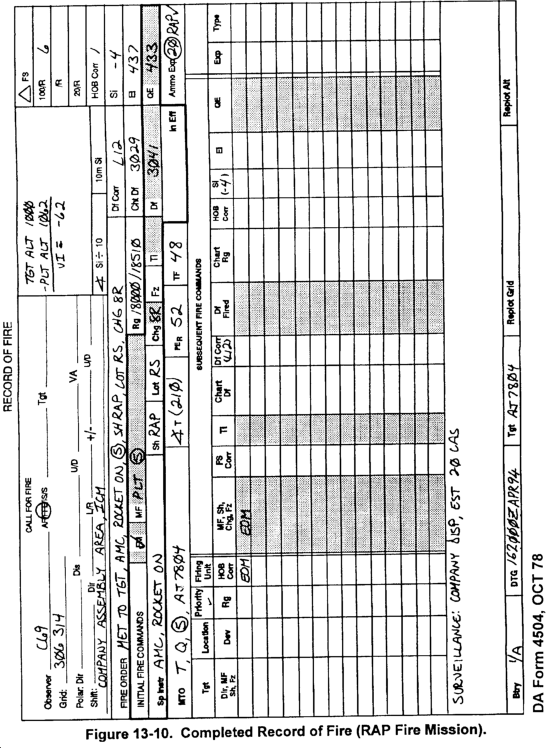
b. Table 13-4 shows the steps for determining firing data for the RAP.
|
NOTE: Figures 13-8 through 13-10 show a completed RAP fire mission. An M109A3 howitzer, propellant M1 19AI, and TFT 155-AO-0 were used. |
3-17. Registration and Determining a GFT Setting
a. Units most likely will not register with the rocket-assisted projectile. An inferred GFT setting can be computed without registration data. Use a subsequent met technique such as met + VE, met to target, or met to met-check gauge point. Assume position constants are zero. As time allows, compute a multiplot GFT setting to improve accuracy at all ranges. Include range corrections for rocket motor temperature (Table E-1) for solving RAP met techniques for rocket motor on mode. For 105-mm howitzers in the rocket motor on mode, met techniques or registrations for RAP will yield unacceptable fuze corrections because of the large fuze-related probable errors. Therefore, do not compute them. For 155-mm howitzers, there is no Table J for fuze correction computations in the RAP TFT, since it can only be fired in the rocket motor on mode.
b. In a combat environment, the unit may conduct registrations with RAP. All of the probable errors involved in firing RAP force the observer to modify a precision registration and severely degrade its accuracy. For this reason, an MPI registration is the best option. However, probable errors also affect the MPI registration. Since the observer obtains spottings of a number of impacts without adjustment, the effects of the probable errors are lessened in comparison to a precision registration. The determined mean point of impact most likely is not as accurate as one determined for an HE MPI registration. However, the RAP MPI registration still provides a GFT setting and increases accuracy. If the unit does register, it also solves a concurrent met and derives position constants for use with later RAP missions. Use the position constants and a subsequent met technique to determine a GFT setting for new missions. As time allows, use the position constants and subsequent met techniques to construct a multiplot GFT setting and improve accuracy at all ranges.
Section III
SMOKE PROJECTILES
Smoke projectiles are used for smoke screens, obscuring smoke, and marking targets for aircraft.
13-18. Description
a. Types. The three types of smoke projectiles areas follows:
(1) Hexachloroethane. Hexachloroethane (HC) smoke (smk) projectiles are available for 105-mm and 155-mm howitzers. They are used for screening, obscuration, spotting, and signaling purposes. The projectile has no casualty-producing effects. This base-ejection projectile is ballistically simailar to the HE projectile. It is fitted with a mechanical time fuze M565 or M577. The round expels smoke canisters that emit smoke for a period of 40 to 90 seconds.
(2) Burster-type white phosphorus. White phosphorus projectiles are available for 105-mm and 155-mm howitzers. They are bursting-tube type projectiles that can be fired with point-detonating (PD) or MTSQ fuzes. The projectile has an incendiary-producing effect and is ballistically similar to the HE projectile. Normally, shell WP is employed for its incendiary effect. The projectile also can be used for screening, spotting, and signaling purposes.
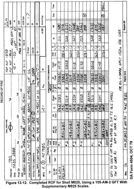
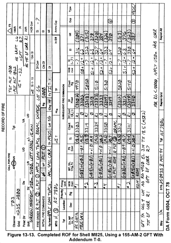
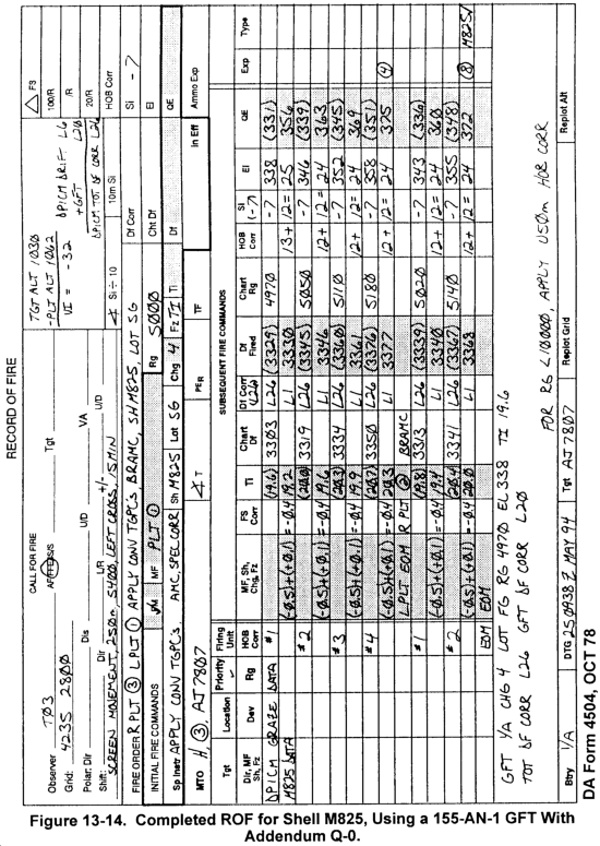
(3) M825 white phosphorus. The M825 WP projectile is an FA-delivered 155-mm base-ejection projectile designed to produce a smoke screen on the ground for a duration of 5 to 15 minutes. It consists of two major components--the projectile carrier and the payload. The projectile carrier delivers the payload to the target. The payload consists of 116 WP-saturated felt wedges. The smoke screen is produced when a predetermined fuze action causes ejection of the payload from the projectile. After ejection, the WP-saturated felt wedges in the payload fall to the ground in an elliptical pattern. Each wedge then becomes a point or source of smoke. The M825 is ballistically similar to the M483A1 (DPICM) family of projectiles.
b. Employment. Smoke is employed by using the quick smoke and immediate smoke techniques.
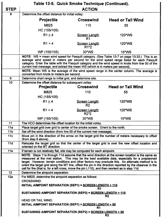
(1) Quick smoke. A quick smoke mission is used to build a screen 100 to 1,500 meters in length, depending on the munition selected. It may be fired as a preplanned target or as a target of opportunity. Targets greater than 250 meters in length should be preplanned because of ammunition constraints and the possible need to segment the target. Quick smoke may be processed as an adjust-fire or FFE mission. Accurate FFE mission processing on preplanned targets presupposes a positive correlation between wind direction at the screen location and that listed on line 00 of the current computer met message, in addition to meeting the five requirements for accurate predicted fire. The following is a list of quick smoke mission characteristics.
- Delivery technique: Quick smoke.
- Type of target: Planned, or target of opportunity, 100 to 1,500 meters.
- Number of howitzers: 2 to 16.
- Type of ammunition: M825, HC or WP.
- Sheaf: Linear.
- Obscuration Time: 5 to 15 minutes.
- Command and Control: Approval of maneuver commander.
- Computations (155 mm): FT 155-AM-2 for HC and WP data, FT 155-AM-2 and FT 155-ADD-T-0 or FT 155-AN-2 and FT 155-ADD-Q-0 for M825 data, and/or corresponding GFTs and GSTs.
|
NOTE: GFTs are available for 155 AM-2 that have M825 scales in place of ICM scales. The M825 data are determined on the basis of the HE quadrant and fuze setting. |
(2) Immediate smoke. An immediate smoke mission may be fired as a separate mission or as a follow-up to immediate suppression. Immediate smoke missions normally are fired by platoon. The initial volley may be fired with shell WP, fuze quick, or a mix of shell WP and shell HC. If additional volleys are fired, all howitzers should fire HC smoke. When firing the M825 smoke round, all howitzers should fire the M825 projectile for the initial and any subsequent volleys. Unit SOP should dictate the number of volleys and which howitzers will fire WP and which will fire HC smoke, if applicable. The following is a list of immediate smoke mission characteristics.
- Delivery technique: Immediate smoke (point suppression). The immediate smoke technique can be used in an immediate suppression mission on a target of opportunity by unit SOP. A mix of WP and HC normally will follow the initial suppression rounds when immediate smoke is requested.
- Type of target: Point or small area of 150 meters or less.
- Number of howitzers: One platoon.
- Type of ammunition: First volley, WP and/or HC; subsequent volleys, HC; or all volleys M825 smoke.
- Sheaf: Parallel.
- Obscuration time: 30 seconds to 5 minutes.
- Command and control: By SOP and/or approval of maneuver commander.
- Computations (155 mm): FT 155-AM-2 for HC and WP data, FT 155-AM-2 and FT 155-ADD-T-0 or FT 155-AN-2 and FT 155-ADD-Q-0 for M825 data, and/or corresponding GFTs and GSTs.
13-19. Quick Smoke
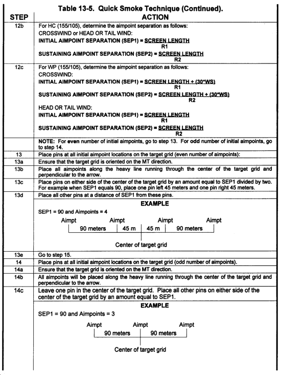
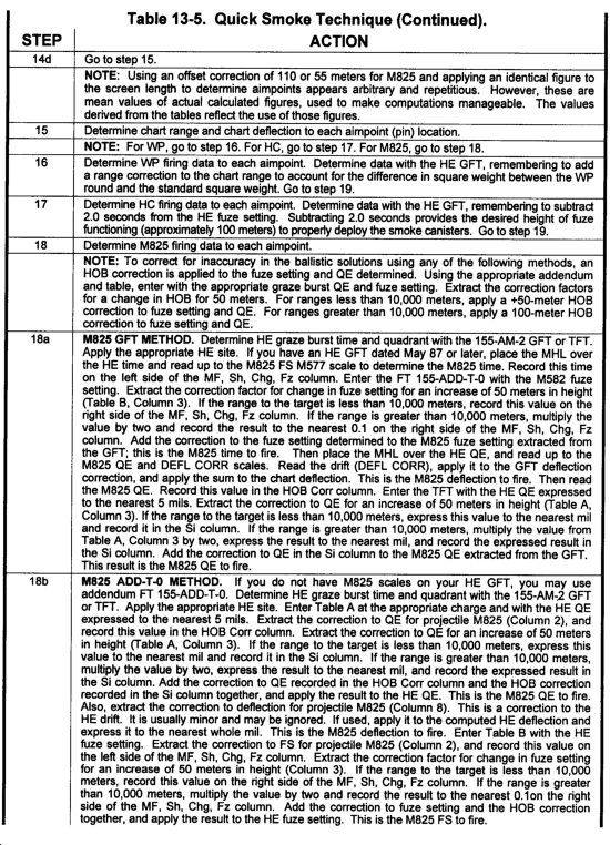
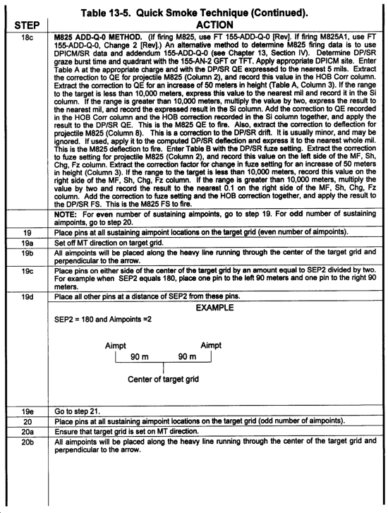
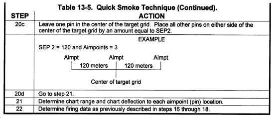
a. Quick smoke missions are fired by using linear sheafs and TGPCs or special corrections. Depending on the atmospheric conditions and the type of smoke desired, the FDC may need to determine two sets of firing data--one set for the initial rounds and one set for the sustainment rounds. The initial rounds establish the smoke screen, and the sustainment rounds ensure the smoke screen is in place for the desired duration.
b. For the FDC to provide an effective smoke screen, the FDO needs to obtain additional information not normally provided for other missions. From the observer, the FDO needs the following:
- The center grid of the desired smoke screen. The FDC will compute offset aimpoints on the basis of the type of munition, wind speed, and/or wind direction.
- The length of the smoke screen.
- The maneuver target (MT) direction. The direction from the point at which the maneuver element will be most susceptible to enemy observation to the target.
- Wind direction in reference to the maneuver target line. The observer must let the FDC know if the wind is a head wind, tail wind, left crosswind, or right crosswind in relation to the maneuver target line.
- The screen time (duration), in minutes.
|
NOTE: The acronym "LMDIRT" is used as a memory aid by the observer to report this information. Maneuever-target line direction. DIRection of wind. Time (duration). |
c. From the met station, the FDO will need to know the relative humidity for line 00 of the latest met message. This should be prearranged by unit SOP.
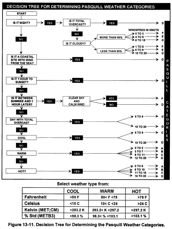
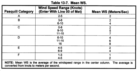
d. When the call for fire is received, the FDO will use a series of tables to determine the Pasquill weather category, mean wind speed, the number of rounds to fire to establish the smoke screen (initial rounds), and the number of rounds to fire to maintain the screen for the desired duration requested (sustainment rounds). If the number of aimpoints, rounds, or guns exceeds unit capabilities, the FDO will notify higher headquarters per unit SOP.
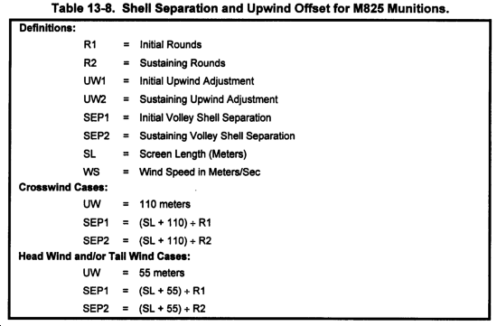
e. Once the number of rounds has been determined, the FDO will go through a series of computations to determine the number of meters between rounds (separation distance) and the necessary upwind offset corrections.
f. The HCO will plot the center grid of the smoke screen on the firing chart and will plot the upwind offset correction on the basis of the wind direction, the maneuver target direction, and the upwind offset correction. He will then plot the aimpoints and determine chart data to each aimpoint.
|
NOTE: It is necessary to determine individual piece data to each aimpoint. Proper manual computational procedures entail the use of the M17 plotting board and the TGPC/Special Correction Worksheet. This must be prepared in advance. Different aimpoint values for the initial and sustainment volleys would normally require the computation of two sets of special corrections for each mission. An alternative method is to plot the aimpoints on the firing chart, and determine firing data for each howitzer on the basis of the base piece location. When converged sheaf TGPCs (recomputed for the appropriate sector and already relayed to each gun section) are applied, the solution approximates the previous method. Errors induced by this alternate method (that is, because of screen location at other than center of the TGPC sector) are offset by decreased computational time and complexity and the nature of the effects of smoke (large area covered per round). This latter method of computation will be used in this chapter. |
g. The computer will determine and announce firing commands for each piece for the initial and sustainment volleys.
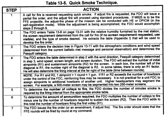
13-20. Quick Smoke Technique
The steps in Table 13-5 are used to determine firing data for the quick smoke technique.
|
NOTE: A study of the RI and R2 factors for HC and WP under poor conditions for smoke (calm, clear, warm, daylight) reveals an excessive number of aimpoints for a given screen width. The use of M825 or other means of screening should be considered in those instances. |
13-21. Smoke Munitions Expenditure Tables and Equations
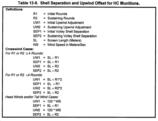
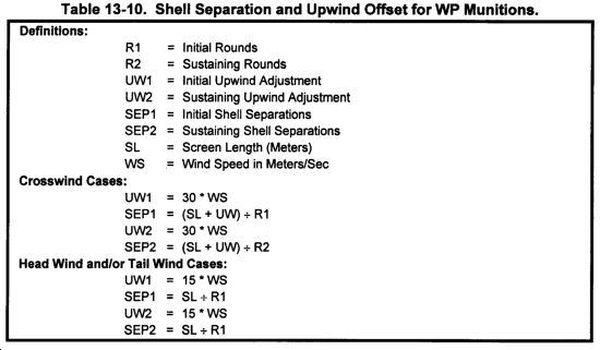
Smoke munitions (M825, M116, and M110) are used to establish and maintain smoke screens. The following tables and equations can help you determine data when firing M825, M116, or M110 smoke munitions. (See Tables 13-8 through 13-10.)
13-22. M825 Smoke Procedures
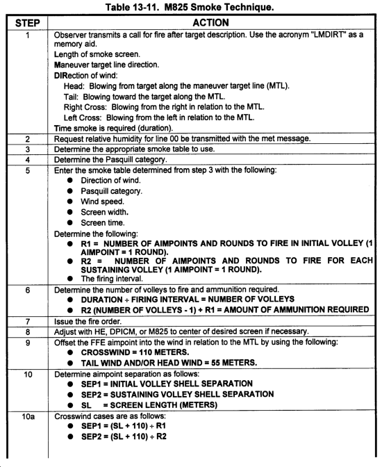
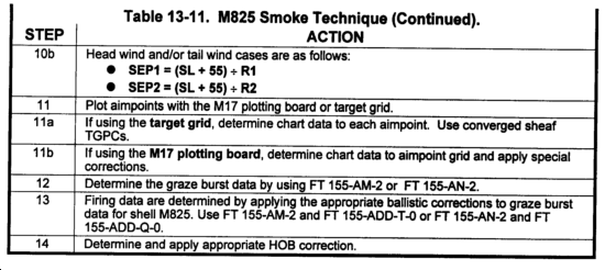
The steps in Table 13-11 are used to determine firing data for shell M825.
13-23. M825 Examples
The following data are used in the examples shown in Figures 13-12 through 13-14.
Known Data:
- Unit: 1/A, four-gun platoon
- Azimuth of fire: 4800
- Altitude: 1062
Conditions:
- Completely overcast afternoon
- Wind speed: 10 knots
- Humidity: 50 percent
- Wind direction: 3900 (left crosswind)
- Met line number: 00
- Assumed screening: Normal visibility
- Screen length: 250 meters
- Duration: 15 minutes
Tactical Solution:
- Pasquill category: D
- Table: I-5
- R1: 4
- R2: 2
- Firing interval: 5 min
- Number of volleys: 15 5 = 3
Aimpoint Separation:
- SEP1: 90 meters
- SEP2: 180 meters
- Offset aimpoint: 110 meters
Section IV
Dual-Purpose Improved Conventional Munitions
Dual-purpose improved conventional munitions are base-ejection (155 mm only), payload-carrying projectiles. These projectiles are fired with M577 MT fuzes and are filled with 88 dual-purpose grenades. During flight, the base of the projectile is blown off and centrlfugal force disperses the grenades radially from the projectile line of flight.
13-24. Overview
The 155-mm DPICM projectile contains two types of dual-purpose grenades (64 M42 and 24 M46). Both types are capable of penetrating more than 2.5 inches of rolled homogeneous armor. They are also capable of fragmentation for incapacitating personnel. The M577 MT fuze is preset to function over the target area and initiate the expulsion charge. The expulsion charge pushes the grenades out of the container and onto the target area. The projectile can be modified for the SR mode. The SR mode causes the round to point detonate so as to be visible to the observer and destroy the submunitions. It also may produce an airburst for high-burst registrations.
13-25. Determining DPICM Firing Data
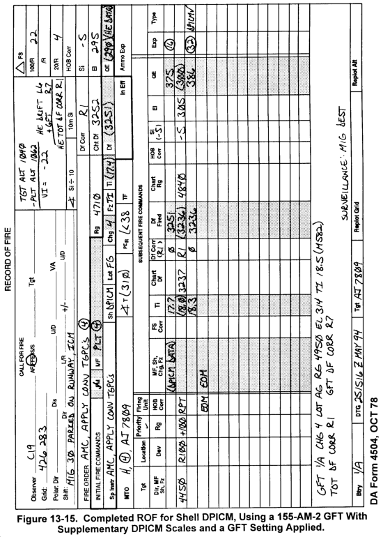
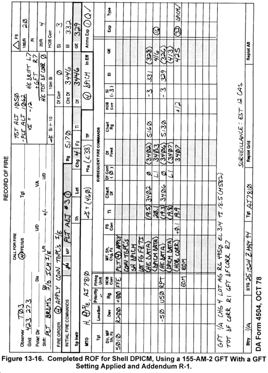
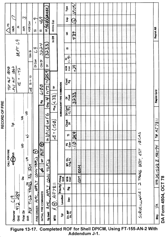
a. There are three ways to determine DPICM firing data. The preferred method is to use the 155-AM-2 GFT with the DPICM scales and a GFT setting. The second way is to use either the 155-AM-2 GFT without a GFT setting or the FT 155-AM-2 and the addendum for DPICM (ADD-R-1). The third way is to use the FT 155-AN-2 and the addendum for DPICM (ADD-J-1). Because the DPICM scales on the 155-AM-2 GFT are based on HE data, HE data from the base (graze burst) scale must be determined before DPICM data can be determined.
(1) To determine the DPICM fuze setting, you must first determine the HE fuze setting. Once the HE fuze setting has been determined, move the MHL over the HE fuze setting on the base scale and read up to the DPICM fuze scale. This is the DPICM fuze setting. Since DPICM is fired with the M577 fuze, the HE fuze setting must be determined from the M582 scale.
(2) To determine the DPICM deflection to fire, you must first have the chart deflection from the HCO. There are three different ways to determine the deflection to fire on the basis of the type of mission being fired.
(a) If DPICM is the only shell fired during the mission, to include the adjustment and fire for effect phases, or if a straight FFE mission was conducted, the drift is taken from the DPICM scale instead of the HE base scale. The MHL is placed over the HE QE on the base HE EL scale. Read up to determine the proper value for drift on the DPICM scale. This drift will be used throughout the remainder of the mission.
(b) If HE is used in the adjust-fire phase and DPICM is used to fire for effect, then as soon as the type of shell is changed (HE to DPICM) a new value for drift must be determined from the DPICM drift scale. This drift will be determined by placing the MHL over the HE QE on the base scale and then reading up to the DPICM drift scale. Compare this DPICM drift to the HE drift to determine the change in drift (DPICM DRIFT - HE DRIFT = CHANGE IN DRIFT). This change in drift is applied to the HE deflection fired (not to be confused with the chart deflection) to determine the DPICM deflection. Another method is to use DPICM DRIFT + GFT DF CORR + CHART DF = DPICM DF TO FIRE.
(c) The last method is to use the appropriate addendum. As soon as the projectile changes, go to the addendum and extract the drift correction from Table A, Column 8. Take this new drift correction, express it to the nearest mil, and add it to the HE deflection fired so that anew DPICM deflection can be determined for this mission.
(3) To determine the DPICM QE, first determine the HE QE. Place the MHL over the HE QE on the base HE EL scale. Now read up to the DPICM QE scale, and determine the QE to fire.
(4) To determine HOB corrections for DPICM, we must use the ADD-R-1. Table A is used to determine the correction factor that will be applied to the QE. Table B is used to determine the correction factor that will be applied to the fuze setting. Remember, the HE data are used to enter the tables, but the correction factors extracted are applied to the DPICM data.
b. To determine firing data without a GFT setting for DPICM, use the 155-AM-2 GFT or the FT 155-AM-2 and the ADD-R-1. This procedure is valid for low-angle fire only.
(1) Using the proper charge and range, begin by determining HE data from the FT 155-AM-2, Table F. Elevation is extracted from Column 2, the fuze setting is extracted from Column 7 (M582), and the drift that will be added to the chart deflection is in Column 8. Site is computed in the normal way and then algebraically added to the elevation.
(2) Once the base HE data have been determined, the ballistic corrections to compensate for the DPICM projectile need to be extracted from the ADD-R-1. Table A of the appropriate charge will yield corrections for QE and deflection. Table A is entered with the HE QE expressed to the nearest listed value. Column 2 will yield the correction factor that must be added to the HE QE to determine the DPICM QE. Column 8 has the deflection correction that must be applied to the HE deflection (chart deflection plus drift) before firing. Table B contains the correction factor that will be applied to the HE fuze setting. Enter Table B with the HE fuze setting, and extract the fuze correction. Apply this correction to the HE fuze setting to determine the DPICM fuze setting.
(3) The HOB of the DPICM projectile is dependent on the charge fired. If the observer transmits a request for an HOB correction, the ADD-R-1 will be used to determine the correction factors that must be applied to the DPICM fuze setting and QE. Table A, Column 3, of the appropriate charge will yield the correction factor for a 50-meter change in HOB. Multiply the correction factor by the number of 50-meter increments needed. Express the answer to the nearest mil. Apply the HOB correction to the DPICM QE. If it was an up correction, add the HOB correction to the DPICM QE; if it was a down correction, subtract the HOB correction from the DPICM QE. Table B, Column 3, of the appropriate charge will yield the FS correction for a 50-meter change in HOB. Multiply the correction factor by the number of 50-meter increments needed. Express the answer to the nearest FS increment. Apply the HOB correction to the DPICM fuze setting. If it was an up correction, add the HOB correction to the DPICM fuze setting; if it was a down correction, subtract the HOB correction from the DPICM fuze setting.
c. To determine firing data without a GFT setting for DPICM, use the FT 155-AN-2 and the ADD-J-1. This procedure is valid for low-angle fire only.
(1) Begin by determining DPICM graze burst data from the FT 155-AN-2, Table F, by using the proper charge and range. Elevation is extracted from Column 2, the graze burst fuze setting is extracted from Column 3 (M577), and the drift that will be added to the chart deflection is extracted from Column 8. Site is computed manually or by using the 155-AN-1 GST and then algebraically adding it to the elevation.
(2) Once the graze burst DPICM data have been determined, the ballistic corrections to compensate for the HOB of the DPICM projectile need to be extracted from the ADD-J-1. Table A of the appropriate charge will yield the corrections for QE. Table A is entered with the DPICM graze burst QE expressed to the nearest listed value. Column 2 will yield the correction factor that must be added to the DPICM graze burst QE so that the actual DPICM QE can be determined. Table B contains the correction factor that will be applied to the DPICM graze burst fuze setting. Enter Table B with the DPICM graze burst fuze setting, and extract the fuze correction. Apply this correction to the DPICM graze burst fuze setting so that the actual DPICM fuze setting can be determined.
(3) If during the course of a fire mission an HOB correction is sent to the FDC for shell DPICM, the ADD-J-1 will be used to determine the correction factors that must be applied to the DPICM fuze setting and QE. Table A, Column 3, of the appropriate charge will yield the correction factor for a 50-meter change in HOB. Multiply the correction factor by the number of 50-meter increments needed. Express the answer to the nearest mil. Apply the HOB correction to the DPICM QE. If it was an up correction, add the HOB correction to the DPICM QE; if it was a down correction, subtract the HOB correction from the DPICM QE. Table B, Column 3, of the appropriate charge will yield the FS correction for a 50-meter change in HOB. Multiply the correction factor by the number of 50-meter increments needed. Express the answer to the nearest FS increment. Apply the HOB correction to the DPICM fuze setting. If it was an up correction, add the HOB correction to the DPICM fuze setting; if it was a down correction, subtract it from the DPICM fuze setting.
|
NOTE: APICM data can be determined in a similar manner. The preferred method is to use the 155-AM-2 GFT with the APICM scales and a GFT setting. The other way is to use the 155-AM-2 GFT without a GFT setting or the FT 155-AM-2 and the addendum for APICM (ADD-1-2). |
d. Figures 13-15 through 13-17 show completed ROFs for all three methods of determining firing data for shell DPICM.
Section V
Family of Scatterable Mines
|
This section implements STANAG 2963 and QSTAG 802. |
The family of scatterable mines adds new dimension to mine warfare, providing the maneuver commander with a rapid, flexible means of delaying, harassing, paralyzing, canalizing, or wearing down the enemy forces in both offensive and defensive operations. Mines can force the enemy into kill zones, change their direction of attack, spend time in clearing operations, or take evasive actions. FASCAM presents an array of air and FA-delivered scatterable mines available to maneuver force commanders. The two types of FA-delivered scatterable mines are ADAM and RAAMS.
13-26. Types of Scatterable Mines
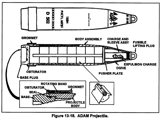
a. ADAM is an antipersonnel mine activated by deployed trip lines. There are 36 wedge-shaped mines contained in the 155-mm projectile. Minefield density can be selectively determined by altering the number of rounds applied. There are currently three densities: low, medium, and high. The mines are expelled from the projectile (approximately 600 meters) over the designated target. Shortly after ground impact, up to seven trip line sensors are released out to a maximum length of 20 feet. The detonators are armed to fiction in the event of any small disturbance. The ADAM mine has lethality out to 15 feet. Self-destruct times are 4 hours for short self-destruct (M731) and 48 hours for long self-destruct (M692). Figure 13-18 shows an ADAM projectile.
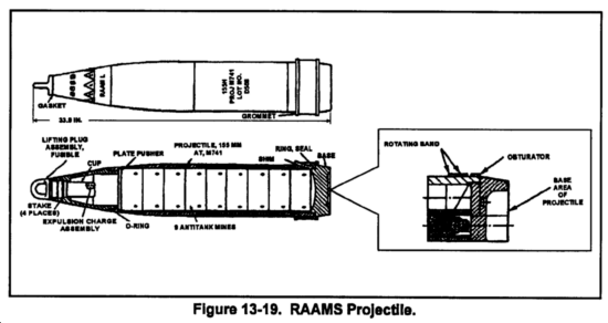
b. RAAMS is effective against armored vehicles. The mines are expelled from the rear of the projectile over the target. After ground impact and roll, the mine is armed and ready to detonate upon sensing a proper armored vehicle signature (electromagnetic). A percentage of the nine RAAMS mines are equipped with an antidisturbance device. RAAMS is highly effective when used in conjunction with the ADAM mine, which helps prevent neutralization by enemy ground troops. There are nine RAAMS mines per 155-mm projectile. Minefield densities and self-destruct times are the same as ADAM (M741 short-destruct, M718 long-destruct). Figure 13-19 shows a RAAMS projectile.
13-27. FASCAM Tactical Considerations and Fire Order Process
a. Two types of minefields can be developed with FASCAM--planned minefield and target of opportunity minefields.
(1) Planned minefields begin with the development of the scheme of maneuver and then the barrier and/or obstacle plan by the G3 and/or S3 and engineer. Before deciding on the employment of ADAM and/or RAAMS, the FSCOORD is brought into the planning process to provide guidance on the availability of FA mines and delivery units. The process is then initiated with the DA Form 5032-R (Field Artillery Delivered Minefield Planning Sheet).
(2) Minefields employed against targets of opportunity (unplanned) must be emplaced immediately because of the tactical nature of the targets. They are requested through the fire support channels at any level. Once the maneuver brigade or division commander has approved the use of FA mines, they can be emplaced appropriately. Normally, targets of opportunity are used when the delivery of the mines can be observed. Aimpoints for target of opportunity minefields can be computed as in a planned minefield. However, this will be time-consuming and may not meet the demands of the tactical situation. Therefore, it is recommended that units establish an SOP for a "standard minefield" to fire when the tactical situation requires an immediate minefield. For example, the unit SOP may be for a 400 x 400 minefield, high angle, medium density, with two aimpoints. The SOP will allow FSOs to determine the number of target of opportunity minefields that are available for the maneuver commander. This determination is based on the unit's FASCAM unit basic load (UBL).
b. Upon receiving a request for a FASCAM minefield, the FDO must begin a detailed process to determine the fire order. The first thing that the FDO must understand is that FASCAM employment is based on a concept known as planning modules. The planning module for RAAMS low angle is 200 meters x 200 meters. The planning module for RAAMS high angle and for ADAM low or high angle is 400 meters x 400 meters. This does not mean that the minefield planner cannot request a minefield that is larger than the planning module. In any FASCAM minefield, the requesting agency defines the minefield size in terms of the length, width, and attitude. The length of the minefield is always the longest axis. The concept of the planning modules is based on the minefield width. In other words, the width of all minefields must be in multiples of the planning module defined above. The FDO will use the length, width, and planning module to determine the number of linear sheafs required to establish the required minefield. The linear sheafs will evenly divide each module and will be parallel to the long axis (length) of the minefield. Refer to paragraph (13) for an example that illustrates this concept.
(1) Once the call for fire on a DA Form 5032-R is received, the FDO will plot the target. In FASCAM missions, DPICM graze burst data, battery-minefield angle (BMA), angle of fire, number of aimpoints, and the desired minefield density must be determined before issuing the fire order.
(2) Plot the minefield linear sheaf, determine the minefield center point of each linear sheaf, and determine the chart range and deflection to the minefield center point(s). Record the chart range and chart deflection on the ROF.
(3) Determine DPICM graze burst data to the center point computed in (2) above. For RAAMS only, determine chart range. For ADAM, determine chart range and DPICM QE.
(4) Determine the battery minefield angle. The BMA is defined as the smaller angle formed by the intersection of the attitude of the minefield and the GT line with the vertex at the center point of the minefield. Using the target grid, set off the minefield attitude and with the vertex at the battery or platoon location, place the RDP against the center point. The smaller interior angle is the BMA. BMA is always less than 1,600 mils. Record this in the computation block of the ROF.
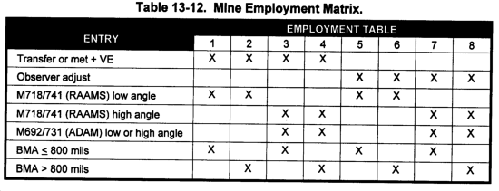
(5) To determine the appropriate mine employment table to use, the FDO must ask three questions:
- What delivery technique am I using?
- Met + VE (FFE).
- Observer adjust (AF).
- What shell and trajectory will I fire?
- M718/M741 (RAAMS) low angle.
- M718/M741 (RAAMS) high angle.
- M692/M731 (ADAM) low or high angle.
- What is the BMA?
- Less than or equal to 800.
- Greater than 800.
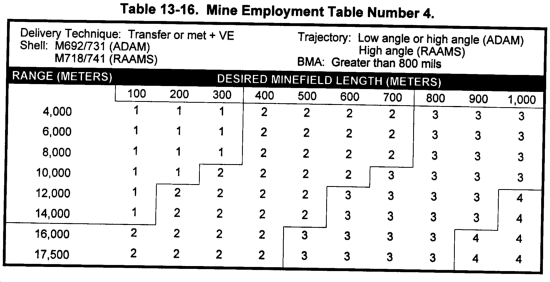
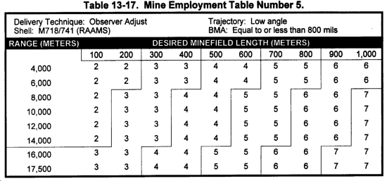
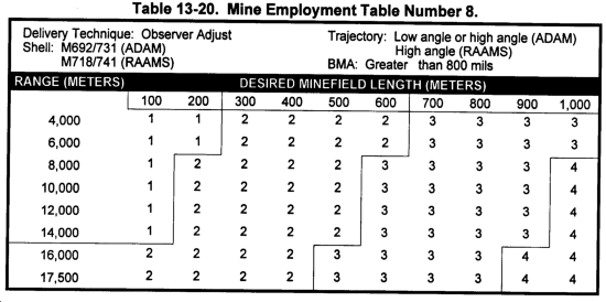
(6) The matrix key is used to determine the mine employment table to use. The table number that is displayed for each of the three entry arguments is the table used for mine employment. See the matrix shown in Table 13-12.
(7) The trajectory makes a difference in the minefield module that can be achieved. RAAMS low-angle planning module is 200 x 200. RAAMS high-angle planning module is 400 x 400. ADAM low- or high-angle planning module is 400 x 400. So, only with RAAMS low angle can you achieve a minefield width of 200 meters, or every 200 meters.
|
NOTE: If ADAM and RAAMS are employed together, then the process for determination of the appropriate mine employment table is done for each shell. |
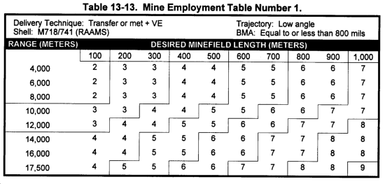
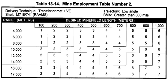
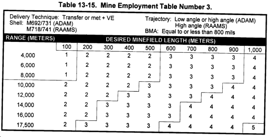
(8) The mine employment tables are used to determine the number of aimpoints required. Review the header information to verify the appropriate table is being used. The entry argument into the mine employment tables are the length (greatest axis) along the top and chart range for entering along the left side of the table (enter with the nearest listed value). If the chart range falls exactly halfway between two ranges, use the lower listed range. The mine employment tables are shown in Tables 13-13 through 13-20.
NOTE: These tables are number of aimpoints per linear sheaf (planning module width). |
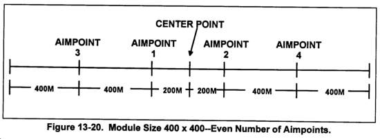
(a) Module size 400- by 400-meters--even number of aimpoints. Place aimpoints 200 meters left and right of the center point along each centerline. Place the others at intervals of 400 meters. (See Figure 13-20.)
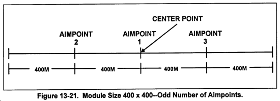
(b) Module size 400- by 400-meters--odd number of aimpoints. Place the first aimpoint at the center point of the minefield. Place the others at intervals of 400 meters left and right of the center point along each centerline. (See Figure 13-21.)
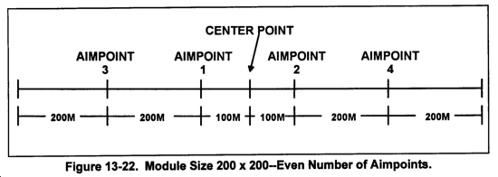
(c) Module size 200- by 200-meters--even number of aimpoints. Place the aimpoints 100 meters left and right of the center point along each centerline. Place the others at intervals of 200 meters. (See Figure 13-22.)
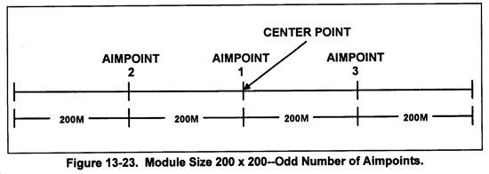
(d) Module size 200- by 200-meters--odd number of aimpoints. Place the first aimpoint at the center point of the minefield. Place the others at intervals of 200 meters left and right of the center point along each centerline. (See Figure 13-23.)
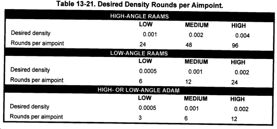
(10) On the basis of the desired density, enter Table 13-21 below to determine the number of rounds needed to achieve that density.
|
NOTE: A density of .001 means that there will be approximately one mine every 1,000 square meters. In other words, there will be one mine in every 32- x 32 meter area. These density numbers are used for planning purposes only. Dispersion of the projectiles in the target area will dictate the actual pattern of mines. Tables 13-22 and 13-23 show recommended minefield densities. |
(11) Now, using all available information, the FDO issues the fire order and the computer records it on the ROF.
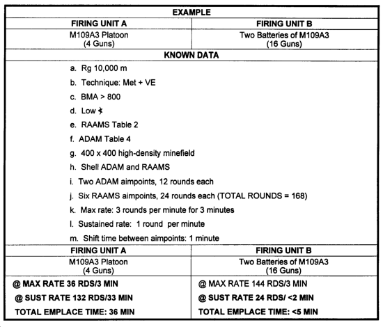
(12) There are some additional tactical considerations to consider when determining which firing unit(s) will deliver the mines on target. The FDO must consider the total emplacement time, the BMA angles of the firing units, the units available, distribution of FASCAM ammunition, and distribution of aimpoints. When firing a minefield containing both ADAM and RAAMS mines, RAAMS should be fired first to prevent premature detonation of ADAM mines.
|
NOTE: The above example is for illustrative purposes only and does not include the time required to shift between aimpoints. |
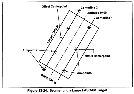
(13) The FDO must also consider how to segment a target that is larger than the established planning modules. Segmenting a large target may require the FDO to establish two or more linear sheafs in the target area. The tactical considerations discussed in paragraph (12) are considered for each linear sheaf as if it were a separate fire mission. This decision to segment a large target is normally the responsibility of the battalion FDO.
(a) To illustrate this concept, consider the following situation:
- Weapon: M109A3
- Minefield size: 1,000 x 800
- Attitude: 0400
- Munitions: RAAMS
- Angle of fire: High angle
- Module size: 400 x 400
(b) Since the width of the minefield is a multiple of the planning module (800/400 = 2), the FDO can continue with the fire order process. If the establishing agency requests a minefield width that is not a multiple of the planning module, this must be resolved before the FDO can properly segment the target to achieve the desired density. In this example, the FDO will segment the minefield into two targets of 1,000 x 400 each. On the firing chart, the FDO will establish a centerline along each separate minefield. The easiest way to do this is to place the target grid over the center of the grid to the minefield and orient along the attitude. Next, place plotting pins left and right of the attitude (200 meters) to establish the offset center points.
(c) The FDO will use the offset center points to determine chart range and the BMA. In some cases, this may cause the number of aimpoints to be different for each centerline, In this example, the chart operator determined the following data:
Centerline 1:1/A RG 10,930, BMA 1150
Centerline 2:1/A RG 11,350, BMA 1170
(d) The FDO will enter the appropriate minefield employment table and determine the number of aimpoints for each centerline. Finally, he will determine the aimpoint spacing along each centerline. In this example, the FDO determined the following data:
Centerline 1 Centerline 2
Mine Table: 4 Mine Table: 4
Entry Range: 10,000 Entry Range: 12,000
No Aimpoints: 3 No Aimpoints: 4
Spacing: Center, 400 L/R Spacing: 200 L/R, 400
(e) The remainder of the tactical considerations are performed as described in the steps from paragraph 13-27b(l3). Figure 13-23 depicts the results achieved from the above situation.
13-28. Technical Fire Direction Procedures
a. Now that the fire order is issued, technical fire direction must be determined by using DPICM graze burst data and then converting these DPICM data to either RAAMS or ADAM data. To convert these DPICM data, use the FT 155-ADD-L-1 (for ADAM) or FT 155-ADD-N-1 (for RAAMS). The preferred technique is to conduct a DPICM registration and transfer the GFT setting. Other techniques used are met + VE or met to target. The computer records the initial fire commands through the Fz block and the MTO block on the ROF.
b. Now plot the aimpoints on the (target grid) firing chart (placing plotting pins left and right along the centerline arrow, representing the attitude) and determine chart data to the aimpoints. These are aimpoints where you want the rounds to impact. For ADAM, these chart data are not recorded on the ROF but are used to determine VI and site (we determine site to the actual impact of the rounds, not to an offset aimpoint location). For future use, record the chart range, VI, and site in the computational space of the ROF. For RAAMS, record the chart data, VI, and site for each aimpoint.
c. Since low-level winds will cause ADAM mines to be blown away from the intended aimpoint, a modification in meters must be made to the location of the aimpoints. This will allow the mines to impact at the intended location. Low-level wind corrections are not computed for RAAMS. For RAAMS, go to paragraph f(3).
d. The computer must enter FT 155-ADD-L-1, Table A, Column 1, with the DPICM graze burst quadrant determined to the center point grid (paragraph 13-27b(3)) and extract the correction for low-level winds from Column 5. This offset correction allows the delivered ADAM mines to be on target for a wind speed of 1 knot. The Low-level wind correction is recorded in the subsequent fire commands portion of the ROF.
(1) Since ADAM has a 600-meter HOB, line 02 from a current met message is used to determine the wind speed and direction. Line 02 is used because 00 = 0 to 250 meters, 01 = 250 to 500 meters, and line 02 = 500 to 1,000 meters.
(2) The computer multiplies the correction factor in paragraph d by the wind speed in paragraph d(1) to determine the total distance, in meters, needed to offset each aimpoint to compensate for low-level winds. Express this value to the nearest 10 meters, and record it on the ROF. This distance in meters, in conjunction with the direction of the wind, will be used to offset the aimpoints.
e. The HCO uses the target grid to offset the aimpoints.
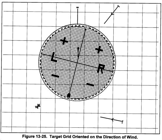
(1) The HCO places the target grid over the center point and sets off the direction of wind. Remember, this is the direction from which the wind is blowing. The HCO then offsets the center point into the wind by the distance determined in step d(2). (See Figure 13-25.)
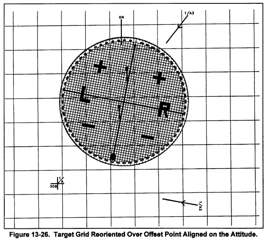
(2) The HCO reorients the target grid over this point, resets the minefield attitude off, and places plotting pins left and right of the center point as determined in step (9) above, using the target grid centerline (arrow). Note that the "head and tail" of the target grid represents the attitude. (See Figure 13-26.)
f. The computer determines FASCAM firing data to each offset aimpoint.
(1) The HCO determines and announces chart range and deflection to the two aimpoints.
(2) The VCO determines site. Using the location and range to the original aimpoints which are recorded in the computational space of the ROF, the VCO determines VI and site.
(3) The computer determines DPICM graze burst time, deflection, elevation, and quadrant elevation to each aimpoint. Since these are not the data to be fired, place the time, deflection, and quadrant in parentheses.
(4) The computer determines and records FASCAM firing data by placing the MHL over the DPICM graze burst time and quadrant. The deflection to fire is the chart deflection to the aimpoint plus the total deflection correction (GFT DF CORR + DPICM DRIFT).
(5) The preliminary FT 155-AN-2 and FT 155-AN-1 TFTs can be used to determine graze burst data for DPICM. The FT 155-AN-2 supersedes the FT 155-AN-1 and is the preferred source of firing data.
(6) The firing table addendums are used in conjunction with the firing tables to determine the firing data FASCAM.
13-29. ADAM
a. Firing Table Addendum L-1 is used in conjunction with the AN-1/AN-2 base TFT to determine firing data for shell ADAM.
b. Table A, Column 1, is entered with the graze burst QE that was determined by using the AN-1/AN-2 TFT. The correction to quadrant is found in Column 2 and is added to the graze burst data.
c. Table B, Column 1, is entered with the graze burst fuze setting that was determined by using the AN-1/AN-2 TFT. The correction to fuze setting is found in Column 2 and is added to the graze burst data.
d. Subsequent corrections for quadrant are determined from Table A, Columns 3 and 4; for fuze setting, Table B, Columns 3 and 4.
13-30. RAAMS
a. Firing Table Addendum N-1 is used in conjunction with the AN-1/AN-2 base TFT to determine firing data for shell RAAMS.
b. Table A, Column 1, is entered with the graze burst QE that was determined by using the AN-1/AN-2 TFT. The correction to quadrant is found in Column 2 and is added to the graze burst data.
c. Table B, Column 1, is entered with the graze burst fuze setting that was determined by using the AN-1/AN-2 TFT. The correction to fuze setting is found in Column 2 and is added to the graze burst data.
d. Subsequent corrections for quadrant are determined from Table A, Columns 3 and 4; for fuze setting, Table B, Columns 3 and 4.
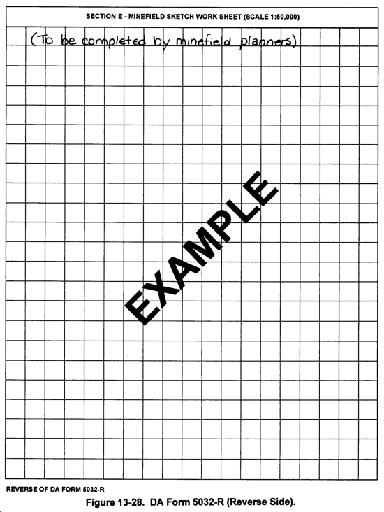
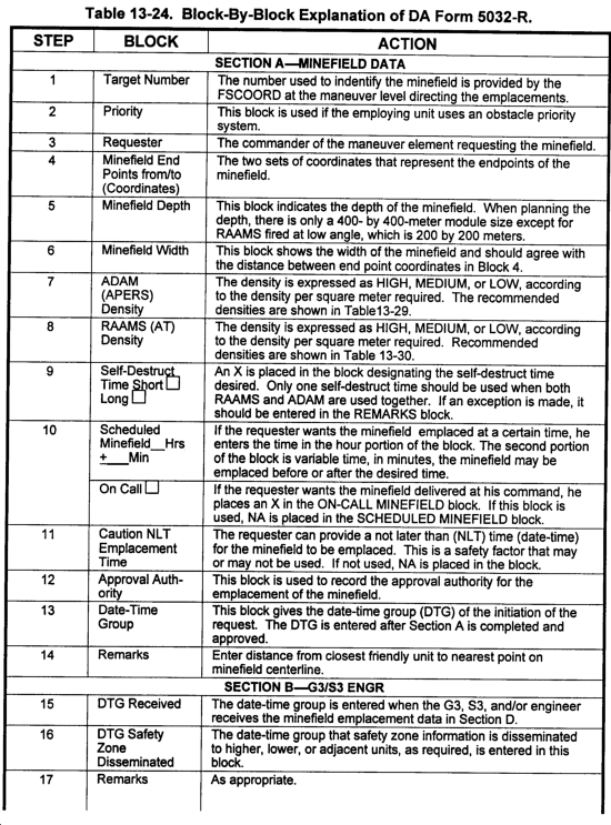
13-31. DA Form 5032-R
a. DA Form 5032-R (Figure 13-27) is used for planned FA-delivered barrier or obstacle minefields, target of opportunity minefields, and minefields established in conjunction with other munitions.
b. The sections shown on this sheet are completed at different levels during the planning and execution sequence. The purpose of the planning sheet is as follows:
(1) Provide a standard procedure for placing planned minefield data into fire support channels.
(2) Provide data for computation and dissemination of a safety zone after minefield emplacement.
13-32. Planned Minefields
The planning sequence starts with the G3, S3, and engineer with guidance from the FSCOORD.
a. Section A is completed by the G3, S3, and/or engineer when requesting an FA-delivered scatterable minefield to support a barrier or obstacle plan.
b. Section B is completed by the G3, S3, and/or engineer to record dissemination of safety zones.
c. Section C is completed by the FSE.
d. Section D is completed by the firing unit FDO.
13-33. Target of Opportunity Minefields and Minefields Established in Conjunction With Other Munitions
These minefields are initiated over fire support channels directly to the firing units. Therefore, the use of the planning sheet starts in reverse sequence.
a. Section D is completed by the firing unit FDO.
b. Section C is completed by the FSE.
c. Section B is completed by the G3, S3, and/or engineer to record dissemination of safety zones.
d. Section A is not applicable.
|
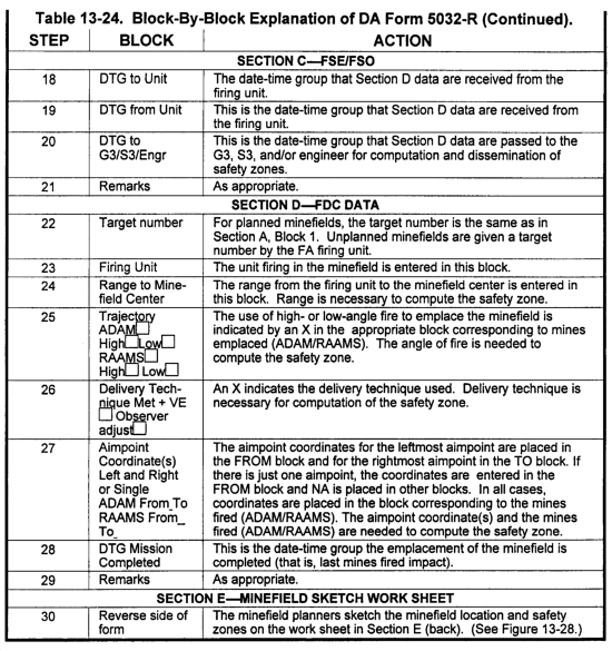
NOTE: A blank DA Form 5032-R is shown in Figures 13-27 and 13-28, and a description of each block is shown in Table 13-24. |
13-34. Safety Zone Determination
a. The G3, S3, and/or engineers are normally responsible for determining the safety zones for FASCAM and disseminating them to the appropriate higher, lower, and adjacent units. The FSCOORD at any level can also determine safety zones for minefields that are fired into the maneuver area for which he is providing support. This would only be done for expediency to support maneuver operations.
b. As a safety check, the FDO should also determine the safety zone before firing FASCAM. The determined safety zone should be compared to the situation map to ensure there are no units within the safety zones for FA-delivered scatterable minefields. The two techniques used to determine the safety zone are as follows:
- Safety zone tables.
- Safety zone templates.
|
NOTE: About 99 percent of all mine delivery missions will result in the entire minefield (minefield modules) being inside the safety squares. |
For both techniques, the following information is required:
- Type of projectile (ADAM or RAAMS).
- Trajectory (high angle or low angle).
- Range to center of the minefield.
- Aimpoint coordinates.
- Delivery technique (met + VE, or observer adjust).
13-35. Safety Zone Tables
The steps for using the safety zone tables are shown in Table 13-25.
13-36. Safety Zone Templates
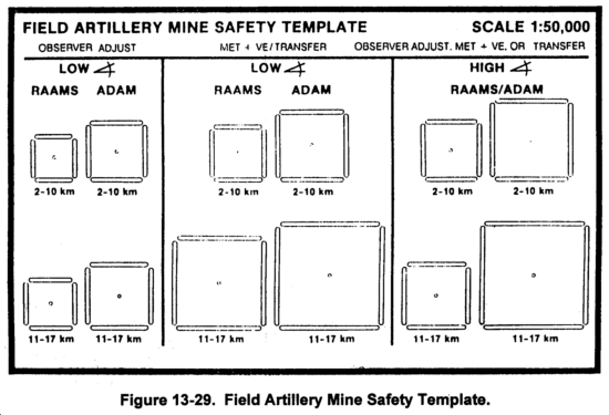
If safety zone templates are available, the steps are basically the same as the safety zone tables. The selected template is centered over the aimpoint locations and the safety zone is traced onto the situation map. The field artillery mine safety template is shown in Figure 13-28.
13-37. FASCAM Employment Steps
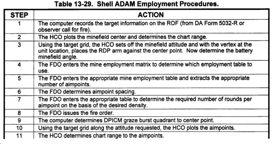
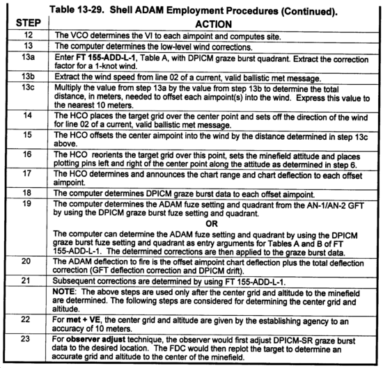
a. Table 13-29 shows the employment procedures for shell ADAM.
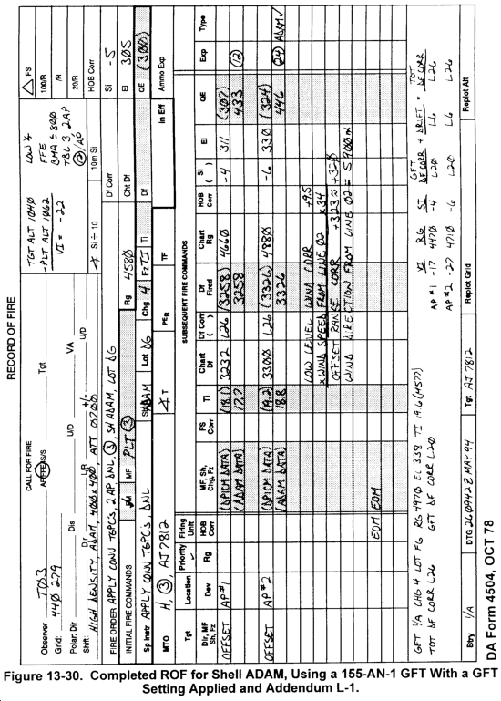
| NOTE: Figure 13-30 shows a completed ROF for shell ADAM. |
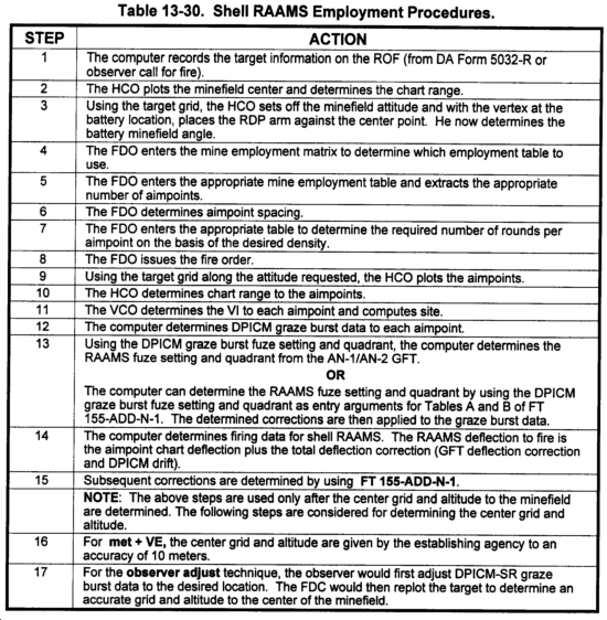
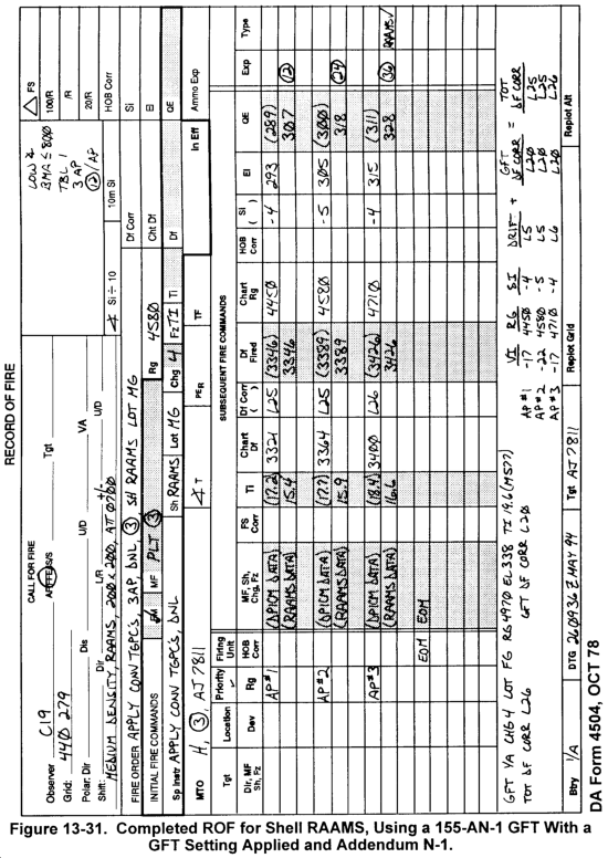
b. Table 13-30 shows the employment procedures for shell RAAMS.
|
NOTE: Figure 13-31 shows a completed ROF for shell RAAMS. |
13-38. Base Burn DPICM (M864)
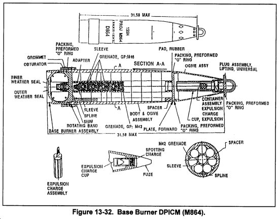
The M864 projectile is a dual-purpose ICM projectile that incorporates base burn technology to increase its range. Base burn technology was developed to reduce the amount of base drag on a projectile, thereby increasing the achieved range. The drag is reduced by a (base) burner unit located on the base of the projectile. Once ignited, the base burner unit bleeds hot gas which causes the flow of air at the base to be less turbulent. The decrease in turbulence causes less base drag. (Base drag accounts for about 50 percent of total drag.) The amount of thrust produced by the base burner unit is negligible and does not serve the same function as the rocket motor on RAP. (See Figure 13-32.)
13-39. M864 Firing Data Computations
a. The current sources of firing data for M864 are the FT 155-AU-PAD and FT 155-ADD-U-PAD. There is also an M864 addendum to the FT 155-AO-0 (RAP). This is an unnamed provisional aiming data (PAD) addendum that is authorized for combat use only. It is used much in the same manner as the FT 155-ADD-R-1 is used to determine M483A1 firing data from M107 firing data.
b. The M864 projectile is not ballistically matched to any projectile currently in the inventory, but because of the similarity of the trajectories, firing data for the M864 can be determined from the M549A1 firing data. Once accurate M549A1 data are determined, corrections for the ballistic difference can be determined from a PAD addendum. The M549A1 QE, which is used to enter Table A of the addendum, can be no higher than 450 mils for charge 7WB (M4A2) or 500 mils for charges 7R (M119A2) and 8S (M203). These are the maximum quadrants for which data in the addendum were determined. The quadrant limitations do not allow the maximum range of M864 to be achieved with this technique. Table 13-31 shows the M864 maximum QE and Range to a target (including the desired HOB) that can be determined from M549A1 data. Table 13-32 depicts the designed M864 maximum QE and ranges. This technique can be used for both FFE missions and adjust-fire missions in which RAP is the adjusting projectile. While this technique of applying ballistic corrections to accurate M549A1 firing data has limitations in range, it represents the most accurate technique. The accuracy of this technique will be increased if used in conjunction with a RAP GFT setting.
13-40. Met to a Target
Because of the amount of time needed to work a met to a target, this technique would be best employed for planned targets. The FT 155-AU-PAD is designed in the same basic format as the FT 155-AN-2 TFT for DPICM and provides graze burst data. Once the graze burst data are determined, corrections from the FT 155-ADD-U-PAD are applied to the fuze setting deflection and quadrant to determine data to yield the appropriate HOB. If MV information has been determined with the M90 chronograph, the MVV is used as the velocity error.
|
NOTE: An MVV for M864 determined by calibration may not be available. The loss in muzzle velocity because of tube erosion (as determined from a recent pullover gauge reading and/or from EFC rounds) can be used as the position VE. |
13-41. M864 Registrations
M864 projectiles can be fired in the SR mode by using the same procedures as for the M483A1. Because of the increased range, registrations may be difficult. Observers may have difficulty determining spottings and corrections, and radar, in the friendly fire mode, has an effective range of 14.7 kilometers.
|
NOTE: If a registration is conducted with the extended range dual-purpose improved conventional munitions (ERDPICM) projectile, the values for range K and fuze K would be computed in the same manner as conventional techniques. |
13-42. Sense And Destroy Armor (SADARM M898)
The M898 SADARM projectile is a base ejecting munition carrying a payload of two target sensing submunitions. The projectile is a member of the DPICM family, and is ballistically similar to the M483A1. The technical fire direction computations are similar to those used for the ADAM projectile, in that low level wind corrections must be applied to the firing solution (because of the high Height of Burst) in order to place the payload at the optimal location over the target area.
13-43. M898 Firing Data Computations
Firing data are computed for SADARM by using the FT 155 ADD-W-0 or FT 155 ADD-W-1 in conjunction with the FT 155 AN-2. The difference between the ADD-W-0 and ADD-W-1 is the Height of Burst of the projectile. The ADD-W-1 increases the HOB to correct for changes in the operational parameters of the projectile. The ADD-W-1 is the preferred method of producing data, although the ADD-W-0 procedure may be used in lieu of the FT ADD 155-W-1 if it is unavailable. (Note: BCS Version 11 will incorporate the ADD-W-1 solution. BCS Version 10 has the incorrect HOB, and automated firings must also incorporate the change in HOB discussed in the ADD-W-0 method).
13-44. Technical Fire Direction Procedures
Technical fire direction procedures consist of four steps (following the Fire Order):
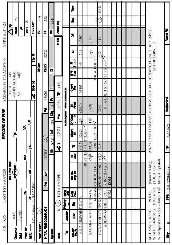
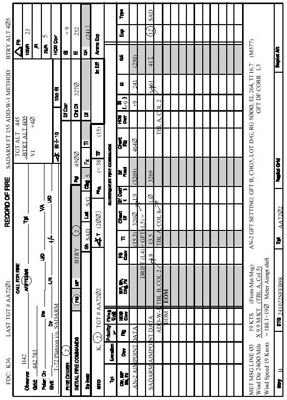
a. Determine chart data to the target location. Chart range, chart deflection, and angle "T" are recorded on the DA-4504 (Record of Fire) in the Initial Fire Commands portion of the form. AN-2 site, elevation, QE, and angle "T" are determined to this target location. Fire commands are not determined from this data! (See Figures 13-33 and 13-34, Sample Records of Fire for SADARM)
b. Offset aimpoint for low level winds. The HCO places a target grid over the target location from step 1. He then applies the Direction of Wind from the Meteorological Message (Extracted from Line 3) and offsets the aimpoint by the distance determined by multiplying the Wind Speed (Extracted from Line 3) times the correction factor from Table "A", Column 5, expressed to the nearest 10 meters. This is the offset aimpoint which is used to determine firing data for SADARM.
c. Determine AN-2 graze burst data to the corrected aimpoint. The HCO announces chart range and deflection to the corrected aimpoint from step 2. These values are recorded in the Subsequent Fire Commands portion of the DA-4504. AN-2 graze burst data are determined to this offset aimpoint, to include Fuze Setting, Deflection to fire, and Quadrant Elevation (Site and angle "T" were determined in step (a.)).
d. Determine SADARM firing data from the ADD-W-0 or ADD-W-1. If data are being determined with the ADD-W-0, use paragraph (1.) below. If data are being determined with the ADD-W-1, then use paragraph (2.) below.
(1) ADD-W-0. First determine SADARM firing data from the ADD-W-0. Then the Height of Burst correction must be applied. Table 13-33 contains the HOB corrections by charge and AN-2 Quadrant Elevation. To extract values from the table, enter with Charge on the left, and with the AN-2 graze burst Quadrant Elevation on the top. If your Quadrant Elevation is less than or equal to the QE listed in Column 2, then use the up correction in Column 2. If it is greater than the value listed in column 3 and less than 800 mils, apply the up correction from column 3. If it is greater than 800 mils, apply the up correction from column 4. The extracted up correction is used to determine the change in Quadrant Elevation (from Table "A", Column 3) and change in Fuze Setting (from Table "B", Column 3) for the change in HOB. These values are then algebraically added to the ADD-W-0 data to determine the data to fire. The FT 155 ADD-W-0 use the following formulas:
DEFLECTION TO FIRE
AIMPT CHT DF+ADD-W-0 DF CORR+GFT DF CORR+AN-2 DFT=M898 DF
FUZE SETTING TO FIRE
AN-2 FS+ADD-W-0 FS CORRECTION+HOB FS CORRECTION=M898 FS
QUADRANT ELEVATION TO FIRE
AN-2 QE+ADD-W-0 QE CORRECTION+HOB QE CORRECTION=M898 QE
Table 13-33, FT 155 ADD-W-0 HOB Corrections
| Column 1 | Column 2 | Column 3 | Column 4 | ||||||||||||||||||||||||||||||||||||||||||||
| |||||||||||||||||||||||||||||||||||||||||||||||
Table 13-34 contains the specific step action drill required to compute SADARM firing data using the ADD-W-0 method.
Table 13-34. SADARM employment procedures (FT 155 ADD-W-0)
|
STEP |
ACTION |
|
1 |
The call for fire is received |
|
2 |
FDO issues Fire Order |
|
3 |
The computer records the target information on the Record of Fire. (Note: All fire commands are announced as they are determined) |
|
4 |
The HCO plots the target location on the firing chart and determines chart range, chart deflection, and angle "T" to the target. |
|
5 |
The VCO determines and announces AN-2 site to the target location. |
|
6 |
The Computer determines and announces the data for the offset aimpoint by extracting the Wind Direction and Wind Speed from line 3 of the meteorological message. The Wind Direction is announced in hundreds of mils. The aimpoint shift correction is determined by multiplying the windspeed times the value from column 5, Table "A" of the Firing Table Addendum. (Note, the entry argument for the addendum is the AN-2 data determined to the target location) |
|
7 |
The HCO places a target grid over the target location and applies the Wind Direction announced by the Computer in step 5. The aimpoint shift correction is applied into the wind. (Note: the Wind Direction from the MET MSG is the direction the wind is blowing from.) |
|
8 |
The HCO determines and announces chart range and chart deflection to the offset aimpoint. The target grid is then reoriented to the OT direction announced by the observer, as all corrections will be based on this aimpoint. Angle "T", however, is determined to the actual target location in step 4. |
|
9 |
The computer determines AN-2 data to the corrected aimpoint. |
|
10 |
The computer uses the data from step 9 to determine SADARM data. |
|
11 |
The computer determines the FS HOB correction necessary by dividing the HOB correction from table 13-33 by 50. This value is then multiplied times the correction factor from Table "B", Column 3 of the ADD-W-0 addendum to determine the HOB FS CORRECTION. |
|
12 |
The computer determines fuze setting to fire. The fuze setting to fire is determined with the following formula: AN-2 FS+ADD-W-0 FS CORR+HOB FS CORR=M898 FS |
|
13 |
The computer determines the deflection to fire. The deflection to fire is determined with the following formula: AIMPT CHT DF+ADD-W-0 DF CORR+GFT DF CORR+AN-2 DFT=M898 DF |
|
14 |
The computer determines the QE HOB correction necessary by dividing the HOB correction from table 13-33 by 50. This value is then multiplied times the correction factor from Table "A", Column 3 of the ADD-W-0 addendum to determine the HOB QE CORRECTION. |
|
15 |
The computer determines the Quadrant Elevation to fire. The QE to fire is determined with the following formula: AN-2 QE+ADD-W-0 QE CORR+HOB QE CORR =M898 QE |
Figure 13-33. Sample Record of Fire for SADARM, FT 155 ADD-W-0 Method
(2) ADD-W-1. No corrections to the Height of Burst are required. The AN-2 graze burst data are used as entry arguments into the ADD-W-1 and the corrections to DF, FS, and QE are and applied. The FT 155 ADD-W-1 use the following formulas:
FUZE SETTING TO FIRE
AN-2 FS+ADD-W-1 FS CORRECTION=M898 FS
DEFLECTION TO FIRE
AIMPT CHT DF+ADD-W-1 DF CORR+GFT DF CORR+AN-2 DFT=M898 DF
QUADRANT ELEVATION TO FIRE
AN-2 QE+ADD-W-1 QE CORRECTION=M898 QE
Table 13-35. SADARM employment procedures (FT 155 ADD-W-1)
|
STEP |
ACTION |
|
1 |
The call for fire is received |
|
2 |
FDO issues Fire Order |
|
3 |
The computer records the target information on the Record of Fire. (Note: All fire commands are announced as they are determined) |
|
4 |
The HCO plots the target location on the firing chart and determines chart range, chart deflection, and angle "T" to the target. |
|
5 |
The VCO determines and announces AN-2 site to the target location. |
|
6 |
The Computer determines and announces the data for the offset aimpoint by extracting the Wind Direction and Wind Speed from line 3 of the meteorological message. The Wind Direction is announced in hundreds of mils. The aimpoint shift correction is determined by multiplying the windspeed times the value from column 5, Table "A" of the Firing Table Addendum. (Note, the entry argument for the addendum is the AN-2 data determined to the target location) |
|
7 |
The HCO places a target grid over the target location and applies the Wind Direction announced by the Computer in step 5. The aimpoint shift correction is applied into the wind. (Remember, the Wind Direction from the Meteorological Message is the direction the wind is blowing from.) |
|
8 |
The HCO determines and announces chart range and chart deflection to the offset aimpoint. The target grid is then reoriented to the OT direction announced by the observer, as all corrections will be based on this aimpoint. Angle "T", however, is determined to the actual target location in step 4. |
|
9 |
The computer determines the FS to fire. The FS to fire is determined with the following formula: AN-2 FS+ADD-W-1 FS CORR = M898 FS |
|
10 |
The computer determines the DF to fire. The DF to fire is determined with the following formula: AIMPT CHT DF+ADD-W-1 DF CORR+GFT DF CORR+AN-2 DFT=M898 DF |
|
11 |
The computer determines the QE to fire. The QE to fire is determined with the following formula: AN-2 QE+ADD-W-1 QE CORR=M898 QE |
Figure 13-34. Sample Record of Fire for SADARM, FT 155 ADD-W-1 Method
|
NEWSLETTER
|
| Join the GlobalSecurity.org mailing list |
|
|
|


