Appendix H
SPECIAL SITUATIONS
This appendix is a supplement to Chapter 13, which details the more common "special situations" missions.
H-1. Final Protective Fires
A final protective fire is an immediately available prearranged barrier of fire designed to protect friendly troops and installations by impeding enemy movements across defensive lines or areas. The normal use of an FPF is to establish prearranged close-in defensive fires, which include other artillery fires, minefield, obstacles, final protective machine gun lines and small-arms fire, and final protective fire of mortars. Each battery is assigned one FPF and normally is laid on that FPF when not firing other missions. The FPF may be fired on prearranged signal or on call from the supported unit. The firing of an FPF maybe repeated on call as often as necessary. When time and ammunition permit, the FPF can be adjusted or check rounds fired. A battery FPF may be fired either individually or in coordination with those of other batteries.
a. Width of FPF. The width (or length) of the FPF that can be covered by a single battery without shifting its fire should not exceed the width of an open sheaf for the battery concerned. When necessary, the width (length) of the FPF may be increased by agreement between the commanders of the artillery and the supported unit. However, the effectiveness of fire will be decreased.
b. Preparation of Data. The actual map location of the FPF is reported by the supported unit through the various fire support channels. The FPF is assigned to an artillery unit, which is responsible for computing the firing data. Since the FPF usually is located within a very short distance of positions occupied by friendly troops, precise computational procedures must be employed and all available corrections must be applied. Special corrections in the form of calibration corrections and position corrections, obtained by use of the M17 plotting board, are determined and applied as individual piece corrections. When the axis of the FPF is other than perpendicular to the direction of fire, additional computations must be made to bring each burst to a desired point on the FPF line.
c. Call for Fire. The call for fire for final protective fires is as outlined in FM 6-30, Chapter 7.
H-2. Computational Procedures
There are two techniques for determining FPF data: observer-adjusted FPF and nonadjusted FPF. Both techniques will result in the determination of firing data that are announced to the howitzers and that are used to lay the howitzers when they are not involved in other fire missions.
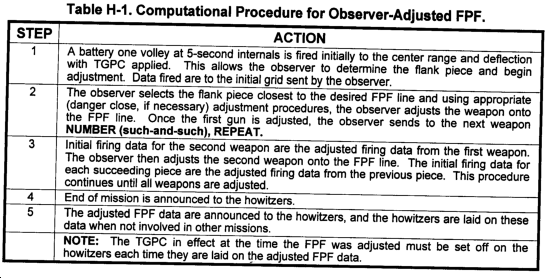
b. Observer Adjusted FPF. The observer will adjust the burst of each round to its desired location on the FPF sheaf. He starts with the flank round that impacts to the location of the desired sheaf and continues the adjustment until all howitzers have been adjusted. (See Table H-1.)
c. Nonadjusted FPF. When the situation does not permit the adjustment of each burst to its location on the FPF sheaf, the FDC determines firing data by using standard FFE techniques, In the call for fire, the observer should include the altitude of FPF and the length, if different from that of an open sheaf. The FDC will compute special corrections with the M17 for a linear sheaf and determine the FPF firing data. The FPF firing data will be announced to the howitzers and, as in observer adjusted FPFs, the howitzers will lay on the FPF data when not involved in other fire missions.
H-3. Laser Adjust Missions
a. An observer equipped with a laser can determine accurate target locations if the laser is accurately located. If the observer has directional control and his accurate location has been recorded at the FDC, he should request first-round fire for effect. If the observer does not feel he can achieve first-round fire for effect on the target, he should request an adjust-fire mission. The FDO may also decide to fire an adjustment if the FDC cannot account for some of the requirements for accurate fire. This may occur even if the observer requests first-round fire for effect.
b. Most laser missions, if not fire for effect initially, should require only one adjusting round. Fire for effect should be requested by the observer unless he determines the lasing of the burst is not satisfactory. Many variables could cause an unsatisfactory lase. For example, an observed burst partially obscured by trees or intermediate hill mass would yield inaccurate land distance to the burst. The total deviation between the target and the adjusting burst does not generally determine if fire for effect is requested. Rather, the observer need only determine if an accurate lase to the burst has been obtained.
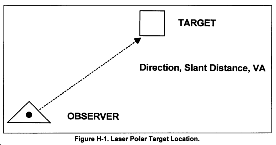
c. The observer uses the polar method of target location to determine the target location. He transmits the target location in his call for fire. (See Figure H-1.)
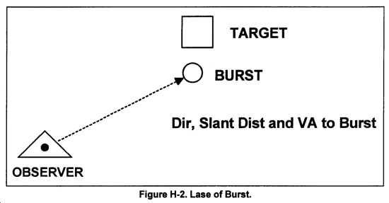
d. The adjusting round is fired and the observer reports the direction, slant distance, and VA to the burst. (See Figure H-2.)
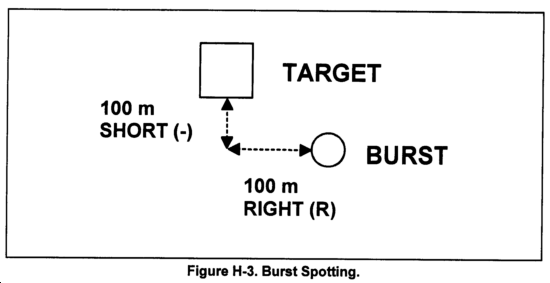
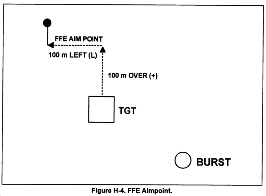
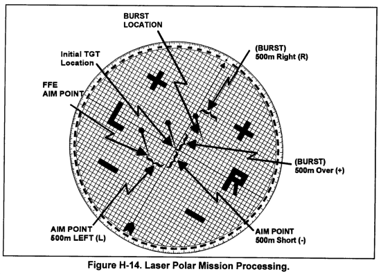
e. The FDC determines the fire for effect aimpoint from the total corrections necessary to engage the target. (See Figures H-3 and H-4.)
f. If additional adjustment is required, continue to plot the burst locations and compare each to the initial target location. Apply each correction determined to the previous aimpoint location not the initial target location.
g. The M17 plotting board may also be used to determine corrections (see Chapter 12).
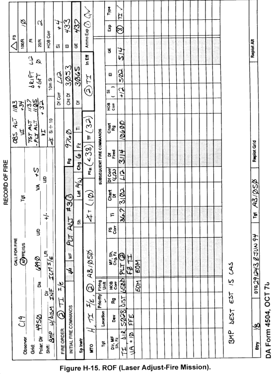
H-4. Laser Adjust-Fire Mission
Table H-2 shows the procedures for a laser adjust-fire mission.
H-5. Radar Adjust-Fire Missions
a. The AN/TPQ-36 and -37 radars are used as counterbattery radars. They have survey capability, which allows them to determine accurate locations of enemy firing bursts. If used in the friendly mode, the radars are capable of determining burst locations of rounds fired by friendly units.
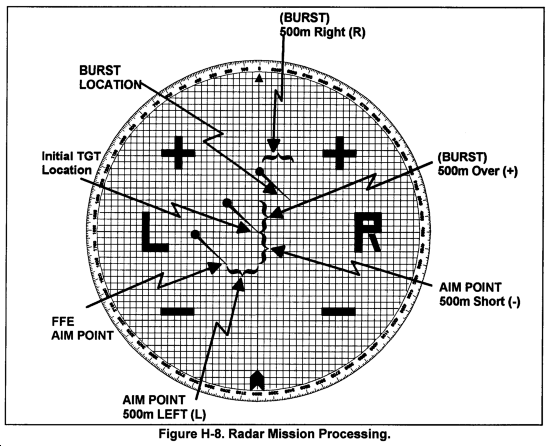
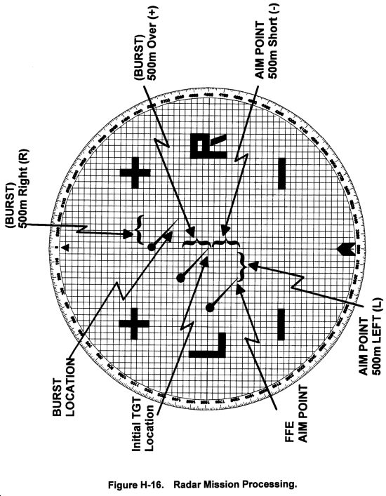
b. The initial target location for a radar adjust-fire mission can be determined by radar in the case of enemy firing units or by another observer. Once the initial target location is established and the initial round is fired, the radar will trace the round and report the spotting of the burst by grid coordinates and altitude. (See Figure H-6.)
c. The FDC then determines the corrections needed to move the burst to the target and determines the FFE aimpoint. (See Figure H-7.)
d. Once the FFE aimpoint location is established, FFE fire commands can be determined.
e. If additional adjustment is required, continue to plot the burst locations and compare each to the initial target location. Apply each correction determined to the previous aimpoint location, not the initial target location. When orienting the target grid for direction, any direction will produce the desired results. Each burst location will be reported by using grid coordinates. The target grid is used only to determine the magnitude of the correction needed and the direction of the corrections relative to the orientation (direction) of the target grid that has been chosen.
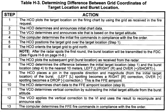
f. Another way to determine the corrections would be to mathematically determine the difference between the grid coordinates of the target location and burst location (Table H-3). The corrections would be applied by using a target grid oriented to grid north (0000). Continued adjustment would be performed by determining the difference between each burst location and the initial target location. Each correction would be applied to the previous aimpoint.
H-6. Destruction Mission
a. General. The purpose of the destruction mission is, as the name implies, to destroy the target. This requires a target hit. The mission is conducted with a single gun and closely parallels precision registration procedures. Given the dispersion suffered by indirect fire weapons and the requirement for a target hit, the great expenditure of ammunition required becomes apparent. This requirement for ammunition and the ensuing possible disclosure of the firing unit make a destruction mission a less desirable method of engaging targets. Whenever possible, other methods or other means of attack should be considered.
b. Conduct of the Destruction Mission. The destruction mission follows the same procedures as a precision registration until the observer establishes a 25-meter bracket. Once it is established, the observer will split the 25-meter bracket by adding or dropping 10 meters and will continue to fire additional rounds. After every third round, additional corrections are announced if necessary. The observer may make corrections after each round. This will continue until the target is destroyed or the observer or FDO chooses to end the mission. At intervals, the observer may request a change of fuze from delay or concrete-piercing to fuze quick to clear rubble and debris around the target.
H-7. Sweep and Zone
Sweep and zone fires provide a method for the attack of large or irregularly shaped targets. The advantage of sweep and zone fires is the ease with which they may be computed in comparison to attacking the target by using special corrections. The disadvantages are the great quantity of ammunition that must be expended and the time required to do so. The resulting loss of surprise and potential for disclosing the firing unit location make sweep and zone fires a less appealing alternative. The FDO should weigh these considerations before attacking targets by using sweep and zone techniques. Possible alternatives are the use of special corrections or dividing the target among a number of firing units.
a. Computation of Sweep.
(1) Sweep fires are used to cover a wide target with fire. (Wide target is described as a target whose long axis lies perpendicular or nearly perpendicular to the GT line.) Sweep fire is similar to traversing fire applied with direct fire weapons. The purpose of the sweep is to cause the guns to fire a number of deflections (at the same quadrant elevation) to place a number of sheafs side by side over the target.
(2) Chart data are computed as with any area target.
(3) The number of deflections to fire is determined on the basis of the width of the target and by the sheaf front.
(a) Determination of sheaf front. The sheaf front is the lateral distance between the center of the flank bursts, plus one effective burst width. The size of the sheaf front depends on the type of sheaf fired and the burst width of the projectile. For an open sheaf, the sheaf front is computed as number of bursts multiplied by the burst width for the projectile. The sheaf front for a circular sheaf is the distance across the center of the circle from burst to burst plus one burst width. If special corrections or TGPCs are being used, the size of the sheaf front will correspond with the sheaf front used to determine those corrections. Converged sheaf should not be used as the concentration of fire on a single point. This is contrary to the purpose for sweep fire. The front for a converged sheaf is one burst width. (See Table H-4.)
(b) Determination of the number of deflections to fire. To determine the number of deflections to fire, divide the target width by the sheaf front. If the result is an even number, the result must be expressed UP to the next higher odd number. Because fire commands will be sent to the guns with the center data and special instructions addressing the size and number of shifts, a center sheaf and equal number of sheafs on either side require that an odd number of deflections be fired.
TARGET WIDTH = NUMBER OF DEFLECTIONS
SHEAF FRONT
(4) The number of mils by which the guns must change the center deflection in order to fire the sheafs is the deflection shift. The deflection shift is computed as the sheaf front divided by chart range in thousands.
(SHEAF FRONT)
CHART RANGE IN 1000s = SWEEP IN MILS
(5) Fire commands are sent as with any area fire mission. The time, deflection and quadrant to the center are announced. The special instruction SWEEP, (the value of the deflection shift) MILS, (the number of deflections) DEFLECTIONS is announced. The number of rounds announced in the method of fire for effect is the number of rounds to be fired at each deflection.
c. Computation of Zone.
(1) Zone fires are used to cover a deep target with fire. (Deep target is described as a target whose long axis lies parallel or nearly parallel to the GT line.) Zone fire is similar to searching fire applied with direct fire weapons. The purpose of the zone is to cause the guns to fire a number of quadrants (at the same deflection) to place a number of sheafs "stacked" over the target.
(2) Chart data are computed as with any area target.
(3) The number of quadrants to fire is determined target by the sheaf depth. by dividing the depth of the
(a) Determination of sheaf depth. The sheaf depth is the distance between the center of the foremost and rearmost burst. The size of the sheaf depth depends on the type of sheaf fired and the burst width of the projectile. For an open sheaf, the sheaf depth is computed as the burst width for the projectile. The sheaf depth for a circular sheaf is the distance across the center of the circle from burst to burst plus one burst width. If special corrections or TGPCs are being used, the size of the sheaf depth will correspond with the sheaf depth used to determine those corrections. Converged sheaf should not be used as the concentration of fire on a single point. This is contrary to the purpose of zone fire. The depth for a converged sheaf is one burst width. (See Table H-5.)
(b) Determination of the number of quadrants to fire. To determine the number of quadrants to fire, divide the target depth by the sheaf depth. If the result is an even number, the result must be expressed UP to the next higher odd number. (Because fire commands will be sent to the guns with the center data and special instructions addressing the size and number of shifts, a center sheaf and equal number of sheafs on either side require that an odd number of quadrants be fired.)
TARGET WIDTH = NUMBER OF QUADRANTS
SHEAF DEPTH
(4) The number of mils by which the guns must change the center quadrant to fire the sheafs is the quadrant shift. The quadrant shift is computed by comparing the elevation corresponding to the range to the center of the target to the elevation corresponding to the center range plus the sheaf depth. The difference is the quadrant shift.
ELEVATION ~ (CHART RANGE + SHEAF DEPTH) - ELEVATION ~ CHART RANGE = ZONE
(5) Fire commands are sent as with any area fire mission is announced. The time, deflection, and quadrant to the center are announced. The special instruction ZONE, (the value of the quadrant shift) MILS, (the number of quadrants) QUADRANTS is announced. The number of rounds announced in the method of fire for fire for effect is the number of rounds to be fired at each quadrant.
|
NOTE: Zone fires are less effective when fired with HE/ti. Since an FS correction is not applied, the chance of graze or high airburst increases as the zone moves from the center. VT is the preferred airburst fuze for shell HE. |
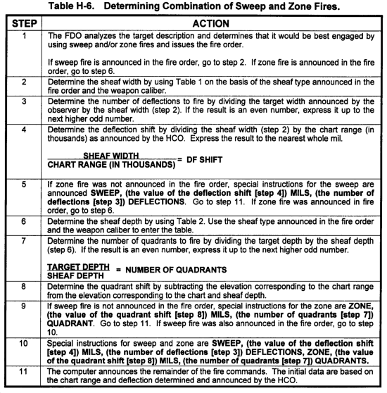
d. Sweep and Zone Fires Combined. Sweep and zone fires are used to attack targets that are both wider and deeper than the sheaf covers. The procedures used are the same as when firing sweep or zone fires individually. The special instructions announced in the fire commands are SWEEP, (the value of the deflection shift) MILS, (the number of deflections) DEFLECTIONS, ZONE, (the value of the quadrant shift) MILS, (the number of quadrants) QUADRANTS. (See Table H-6.)
H-8. Zone-To-Zone Transformation
a. Zone-to-zone transformation is the technique of converting the coordinates and/or azimuths as expressed in one grid zone to coordinates and/or azimuths of an adjacent grid zone. When operating near a grid zone boundary, one of the grid zones will be designated as the primary, or base, grid zone. The other will be referred to as a secondary, or adjacent, grid zone. The decision as to which zone will be primary zone is based on the tactical situation, unit SOP, the directives of the commander, or anticipated location of future operations.
b. Maps printed by the Army Map Service show the differences between universal transverse mercator (UTM) grid zones. Maps that cover an area within 40 kilometers of a UTM zone junction are printed along the border with two sets of grid line numbers (one set for each zone). One set is printed in black. The other set is printed in blue and corresponds to the adjacent grid zone. Marginal information on the maps also indicates the color that applies to each zone.
c. There are two methods of performing zone-to-zone transformation--the two grid sheets method and the graphic method. The two grid sheets method is considered the fastest and simplest.
(1) Two grid sheets method. For this technique, two grid sheets are prepared and joined to form a large chart (a constructed grid sheet) from which chart data across the zone junction can be determined automatically. (See Figure H-9.)
(a) Preparing the grid sheets. The HCO prepares a piece of chart paper (a grid sheet) for each zone involved. Using a plotting scale and a sharp pencil, the HCO reproduces on the grid sheets the exact orientation of the zone junction longitudinal and latitudinal lines as they appear on the map of the area of overlap. The HCO marks the edges to be joined with a fine line that is based on accurate measurements taken from the map. He takes care in cutting and taping so that, when the sheets are put together to form one large chart, measurements from the large chart can be made accurately.
(b) Using the constructed grid sheet. No transformation or computation is needed when firing data are determined from a constructed grid sheet. The coordinates are measured and plotted from the grid lines for the respective area. The observer's azimuth is used as announced, and the target grid is emplaced by using grid north of the observer's zone.
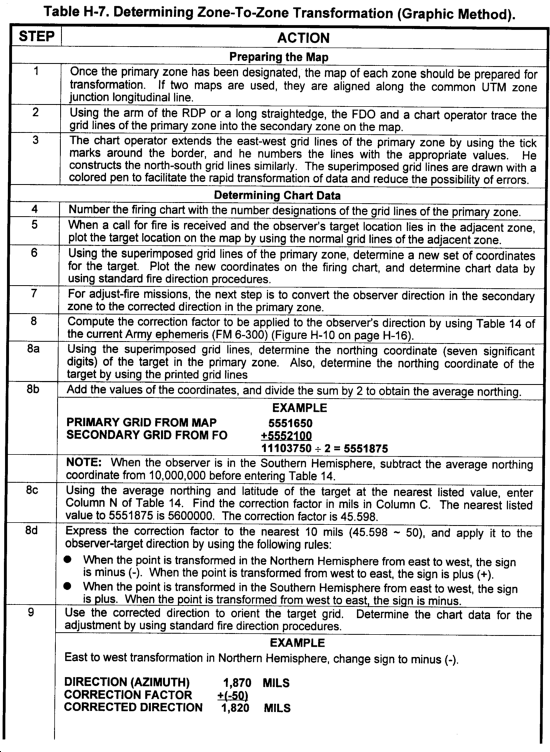
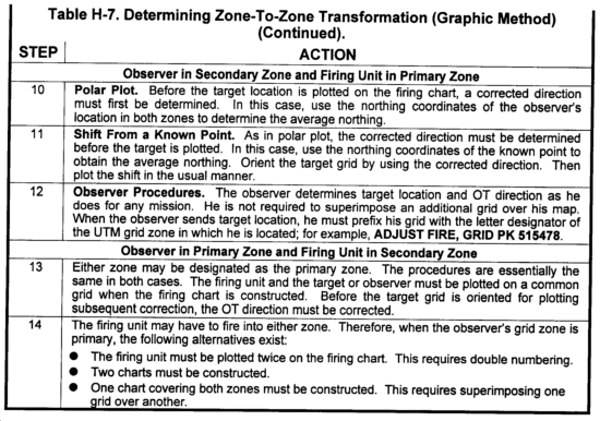
(2) Graphic method (battery in primary zone). The procedures for this method are discussed in Table H-7.
H-9. Aerial Observers
a. Problems Requiring FDC Assistance. Aerial observers may encounter three problems that require special assistance from the fire direction center:
(1) The AO has no fixed direction to the target. Normally, he is moving in relation to the target area. Hence, FDC personnel must be prepared for unusual and changing observer directions or spotting lines. Each adjustment may have a different observer direction (that is, different magnetic or cardinal direction).
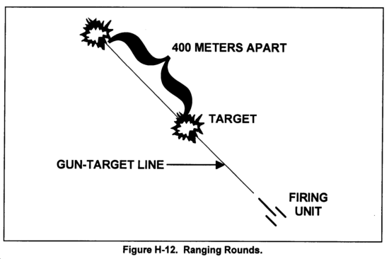
(2) While in the air, the AO may lose his perception of distance and direction. He may request ranging rounds (two rounds impacting 400 meters apart) to help visualize distance and direction in the target area. The observer and FDC personnel must realize that ranging rounds fired along the GT line may disclose to the enemy the general location of the firing unit.
(3) The AO must minimize the time he is exposed to enemy detection. In forward areas, the pilot must fly close to the earth and behind cover as much as possible. Therefore, the AO and his pilot require from the FDC very accurate time of flight, SHOT, and SPLASH so that the pilot can unmask the aircraft 2 to 3 seconds before the round impacts.
b. Observer Direction and/or Spotting Line.
(1) Using GT line adjustment. If the AO knows the location of the firing unit with respect to the target, he may choose to adjust along the GT line. When the AO announces DIRECTION, GUN-TARGET LINE, the HCO plots the target and centers the target grid over the plot with the 0-3200 line (the center arrow) parallel to the GT line.
(2) Using a shift from a known point along the GT line. The AO may announce DIRECTION, GUN-TARGET LINE for a shift from a known point. In this instance, the HCO plots the known point, centers the target grid, and orients it parallel to the gun-target line. He then plots the observer's shift and determines chart data. He then rotates the target grid around the new pinhole so that the arrow is parallel to the GT line.
(3) Using helicopter instrument readings for direction. When the AO's aircraft is moving in relation to the target area, the AO may use an aircraft instrument reading for his observer direction. As this direction is expressed in degrees, FDC personnel must convert the reading to mils by using the following formula:
DIRECTION IN DEGREES x 17.8 = DIRECTION IN MILS
For example, if the direction is 250°, the direction in mils is 4,450 (250° x 17.8 mils = 4,450 mils).
|
NOTE: In preparing for AO missions, the VCO (recorder) should mark a target grid in degrees or prepare a conversion chart for quick conversion from degrees to mils. |
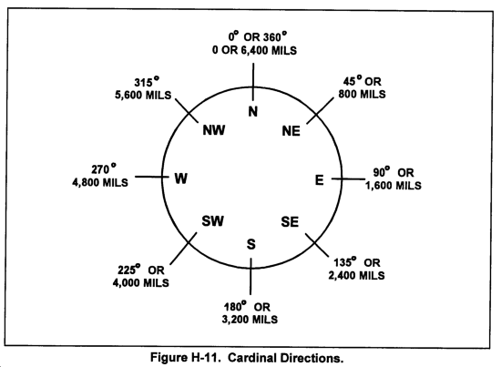
(4) Using a cardinal direction. The AO may choose to adjust along a cardinal direction (one of the eight principal points of the compass) (Figure H-11). When the observer announces a cardinal direction, the HCO converts the direction to mils and orients the target grid to that direction. For example, FDC personnel would convert direction southwest (SW) to direction 4,000 mils. The observer may also shift from a known point by using a cardinal direction. The preferred method for sending direction to the FDC is to send it in degrees if possible.
(5) Using a spotting line. The AO may adjust along a spotting line formed by natural or man-made terrain features, such as roads, railroads, canals, or ridge lines. Before flight, if possible, the AO selects the line, determines the direction, and notifies the fire direction center. While in flight, he may select a line that is more readily identifiable and convenient. The AO may describe the feature in detail and have FDC personnel use a protractor to determine the direction from a map. The HCO orients the target grid over the target location on this new direction.
H-10. Ranging Rounds
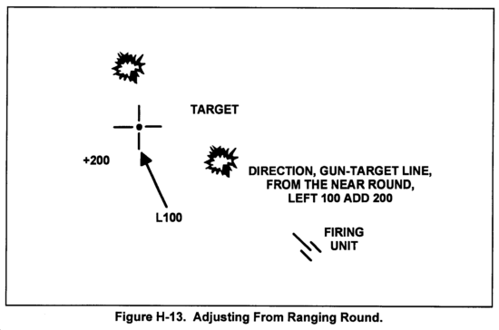
In his call for fire, the AO may announce REQUEST RANGING ROUNDS. This indicates that he wants to see a volley of two rounds that impact 400 meters apart at relatively the same time. Ranging rounds (Figure H-12) are fired only as a last resort, since they reveal the general location of the firing position. These rounds are fired along the GT line. The HCO determines initial chart data, and the computer determines initial firing data for the adjusting piece. The computer then adds 400 meters to the announced chart range. Using the new range and the initial chart deflection, the computer determines firing data for the second piece to fire in the volley (usually the other piece in the center platoon). Ranging rounds are fired at the same time by firing AT MY COMMAND. The AO observes the impact of the round and determines the corrections necessary to hit the target. He bases his corrections on the round that lands nearest the target. He bases his corrections on the round that lands nearest the target. He must specify to the FDC from which round he is adjusting, and the HCO plots the shift accordingly (Figure H-13).
H-11. Time of Flight, Shot, and Splash
In the message to observer, the FDC must specify the time of flight. On all volleys, the FDC must promptly announce SHOT and SPLASH. The FDC should report changes in the time of flight as the mission progresses.
H-12. Untrained Observers
a. Calls for fire from untrained personnel acting as ground observers require close attention and initiative from every member of the fire direction center. The FDC personnel must be prepared to assist the untrained observer in his call for fire and adjustment of artillery.
b. FDC personnel must take the initiative if the observer is hesitant or confused in his request for fire support. They must ask leading questions, such as the following:
(1) Where is the target?
(a) What are the grid coordinates of the target?
(b) Where is the target in relation to a readily identifiable natural or man-made feature?
(c) Where are you? How far is the target from you and in what direction is it?
(2) What is the target?
(a) Is the target personnel, vehicles, installations, or equipment?
(b) What is the size of the enemy force?
(c) What is the enemy force doing at present?
(d) If the enemy force is moving, in what direction is it moving? How fast is the force moving?
(3) How close is the target to you? If the target is within 600 meters or closer to other friendly troops, the observer may need to "creep" the rounds to the target.
(4) What is your direction to the target?
(a) What is the azimuth to the target in degrees or mils?
(b) What is the cardinal direction to the target (N, NE, E, SE, S, SW, W, NW)?
(c) Is the direction along a natural or man-made feature?
(5) What effect do you need on target?
(a) Is the target shooting at you?
(b) Is it necessary to obscure vision of the target?
(c) Do we need to neutralize or destroy the target?
c. The FDC personnel must explain to the observer what artillery fire he is getting. If necessary, the FDC members must educate or inform the observer as follows:
(1) You will see one round that will look like a cloud of dust. You will get more rounds when you move the burst within 50 meters of the target.
(2) The round is now on the way and will impact in (so many) seconds.
d. The FDC personnel must help the observer in making corrections. They must help the observer move the rounds to the target and must be prepared for unusual shifts. To obtain corrections, they should ask leading questions such as the following:
(1) Where did the round land in relation to the target?
(a) Did it land left or right? How far?
(b) Did it land over or short? How far? Ask for distances in meters or in the number of football field lengths.
(2) Did the round land closer than the previous round?
|
NOTE: The FDO should consider using shell WP to help the observer locate initial rounds. |
e. The FDC personnel must use sound judgment. They must decide whether to require the observer to authenticate. They must watch for possible observer misorientation. Also, FDC personnel must help the observer determine when satisfactory effects on the target have been achieved. In all cases, the FDC personnel must take the initiative.
H-13. Example Problems
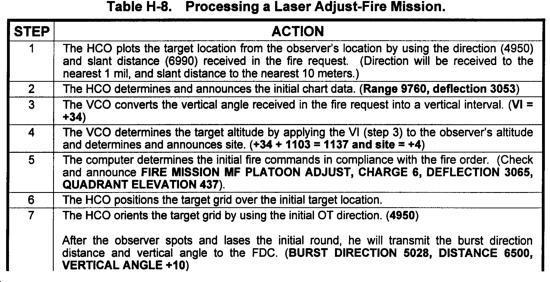
a. Process a Laser Adjust-Fire Mission. The observer transmits the following call for fire:
H57 THIS IS C19, AF POLAR, OVER.
DIRECTION 4950, DISTANCE 6990, VA PLUS 5, OVER.
BMP WITH DISMOUNTED INFANTRY, ICM IN EFFECT, OVER.
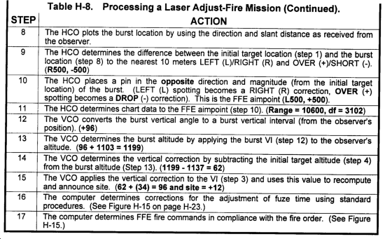
The procedures for processing a laser adjust-fire mission are discussed in Table H-8.
b. Process a Radar Adjust-Fire Mission. The procedures for processing a radar adjust-fire mission are discussed in Table H-9.
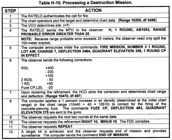
c. Process a Destruction Mission. The observer transmits the following call for fire:
H57 THIS IS T03, ADJUST FIRE, OVER.
GRID 375 257, OVER
CONCRETE BUNKER, DESTRUCTION, CP IN EFFECT, OVER.
The following GFT setting is available:
|
NOTE: This GFT setting was obtained from the radar registration mission located in Chapter 10. GFT 1/A, Chg 7, Lot AW, Rg 12100, El 476, Ti 39.3 (M582) |
The procedures for processing a destruction mission are discussed in Table H-10. Figure H-18 shows a ROF for a destruction mission.
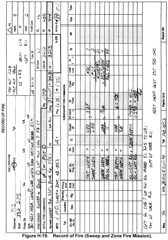
d. Process a Sweep and Zone Fire Mission. The observer transmits the following all for fire:
H57 THIS IS T03, FIRE FOR EFFECT, OVER.
GRID 359 284, OVER
BATTALION ASSEMBLY AREA, LENGTH 600,
WIDTH 300, ALTITUDE 0800, ICM, OVER.
The following GFT setting is available:
GFT 1/A, Chg 7, Lot A/W, Rg 10,000, El 325, Ti 29.1 (M482)
Tot Df Corr R2
GFT Df Corr R11
The procedures for processing a sweep and zone fire mission are discussed in Table H-11. Figure H-19 shows a ROF for a sweep and zone fire mission.
|
NEWSLETTER
|
| Join the GlobalSecurity.org mailing list |
|
|
|


