| Appendix B. Steel Pipeline Systems |
a. Steel Pipe. Steel pipe (light- and standard-gauge wall thickness) is available in 20-foot lengths with diameters of 4, 6, and 8 inches. Steel pipe is coupled using a standard, two-piece split-ring coupling. The coupling uses two half-moon sections, which are bolted together over a one-piece gasket. The average time required to couple together two sections of steel pipe is 5 minutes.
b. Lightweight Steel Grooved Pipe. This pipe is made of light gauge steel with API STD5L pipe nipples welded to each end. The pipe ends are single-grooved for use with bolted couplings. This pipe comes in 20-foot sections with 4-, 6-, 8-, and 12-inch nominal IDs. Because of its thin wall, lightweight steel pipe should not be buried nor used for submerged stream crossings or in populated areas and locations where fire and damage hazards are acute.
c. Standard-Weight Steel (API STD5L) Pipe. This regular commercial-type pipe, which is manufactured to the standards of the API, is used when lightweight pipe or tubing is unavailable or unsuitable. The pipe comes in 20-foot sections grooved for coupling and in random lengths and diameters beveled for welding.
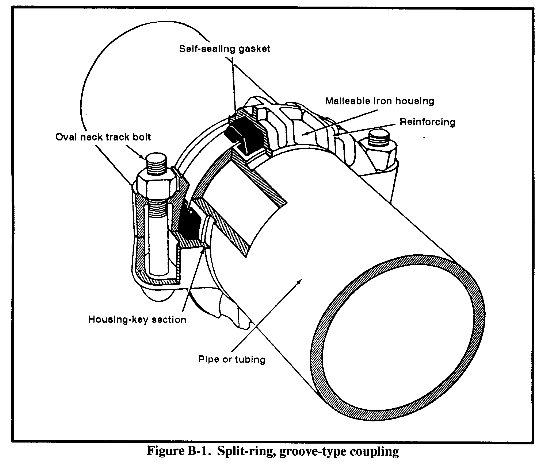
d. Bolted Coupling. This is a standard, split-ring, groove-type coupling (Figure B-1). It consists of two housing segments; two bolts and nuts; and a synthetic-rubber, oil-resistant, self-sealing gasket. The coupling and gasket are designed so that the pipe joint seals under pressure and vacuum. The coupling provides a sufficient amount of angular deflection and slack adjustment for expansion and contraction of the line between adjacent joints.
When using bolted couplings, the crew consists of a crew leader, wrenchman, wrenchman's helper, stabber, jackman, swabber, and pipe-end cleaner. The bolted-coupling crew will normally require--
- Two 20-inch hinged socket wrench handles.
- Two sockets to fit size of pipeline coupling nut and wrench.
- File.
- Dauber brush.
- Lazy board.
- Two pipeline jacks with two snakes.
- Pipeline cleaner swab with one snake.
- Wooden blocks (4 by 4 by 10 inches) with carrying rope attached.
- Full half-gallon bucket or one-gallon bucket half filled with GAA grease.
- Cleaning rags.
e. Pipe Saw, 8-Inch Capacity for Hazardous Locations. This is a reciprocating-type saw powered by an air motor. You can cut steel, cast iron, and stainless or alloy steel pipe as well as bar stock structural and rail. Use this saw to cut out a damaged portion of pipeline when operating in hazardous locations. You can operate when clearances are at minimum and you can make a straight, right-angle cut.
f. Tapping Machine. This machine is used for tapping into a pressurized pipeline to establish a service tap or to install a pressure-relief device. This operation can be done without shutting down the pipeline system. The machine uses a hole saw; a holder-pilot performs the cutting operation. He retains the separated pipe after he completes the cut and allows for its removal.
The tapping machine is lightweight and easy to operate and has an adjustable automatic-feed rate for any cutting condition. The advance rate for cutting is set by the feed-adjustment knob. This knob engages a friction-type clutch that automatically regulates the feed rate. The operator loosens (slow feed) or tightens (faster feed) the feed-adjustment knob to obtain the correct amount of force for the task. The machine comes with a ratchet crank for manual operation.
g. Deadweight Tester. This tester is used to calibrate pressure gauges, verify the set points of spring-loaded relief valves, and provide precise pressure readings for pipelines. The tester uses known weights that directly correlate to known pressure gauges and the verification of set points for spring-loaded relief valves.
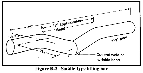
a. For 8-inch Steel Tubing. Procedures for this tubing, because of weight (210-pound tubing), are different than for lighter pipelines. A saddle-type carrying bar (Figure B-2) and one extra person in the crew are required for constructing the 8-inch tubing pipeline. This extra person is a second helper who assists in raising the new section onto the lineup cage and in lowering it. The rest of the coupling operations are the same as those for a 4- or 6-inch line. Except for size, the 8-inch lineup cage and pipe-cleaner swab are identical to those used on the smaller pipe. Coupling procedures for 8-inch steel tubing are as follows:
- The second helper assists the wrenchman's helper to raise their end of the tubing section and guide it onto the lineup cage, while the stabber and jackman handle the other end.
- The second helper moves to the other end and assists the jackman and stabber in aligning the section, as directed by the wrenchman.
- The second helper assists the jackman and stabber in lowering the new end of the pipeline on the lazy board. Then the second helper assists the wrenchman's helper with the next section.
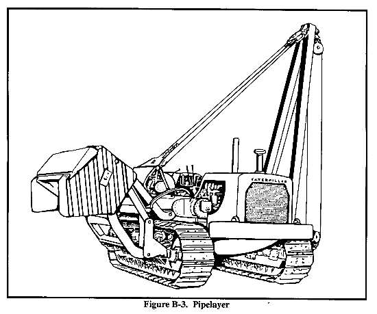
b. For 8- and 12-Inch Standard Steel Pipe and 12-Inch Steel Tubing. Do not manually handle pipe sections heavier than the 6-inch (300-pound) standard-weight pipe. Use powered equipment to off-load the pipe and couple one section at a time. You can stockpile the pipe along the pipeline trace. If you do, use a pipelayer (Figure B-3) to handle the pipe. (The pipelayer is a commercial piece of equipment that must be leased.)
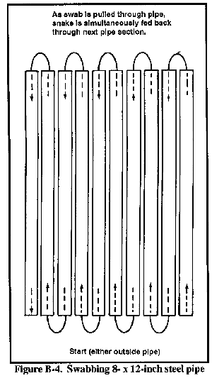
(1) Swabbing and Cleaning. The swabber and pipe-end cleaner swab all of the pipe on a load, one row at a time, in a single operation. (They can swab the pipe while it is still on the truck or in a stockpile.) With one man at each end, they insert a snake in either outside pipe of the top row and pass it through to the other end. The man at the end where the snake is coming through pulls it through the first pipe and simultaneously feeds the snake back through the next pipe in the row. The men repeat this operation until they swab all the pipes (Figure B-4).
(2) Moving the Pipe. The pipe is picked in the middle with an automatic clam-type release hook attached to the hoisting line of the stringing boom. The pipe joint is first raised only a few inches from the pipe. The swabber and pipe-end cleaner, working at opposite ends, clean and file the pipe land and groove on each end at the same time. At the same time, the wrenchman and helper (one team) and the jackman and stabber (another team) construct cribbing of 4- by 4-inch by 3-footlong blocks. This cribbing takes the place of the lazy board and pipe jack. Each of the blocks is tied together with rope. Doing so allows the wrenchman's helper to drag one cribbing set at a time when moving it to the next location.
(3) Positioning the Pipe. After the pipe ends are cleaned, the pipe section is swung into approximate alignment on the pipeline. The stabber inserts the lineup-cage snake through it (only one snake is used). The jackman and wrenchman's helper guide the pipe joint into position on the lineup cage protruding from the end of the line. The stringing-boom operator raises or lowers the load and extends or retracts the boom, as directed by the stabber or wrenchman. Once aligned, the jackman keeps the joint aligned by leaning or shoving against the end.
(4) Installing the Coupling. After tightening the coupling, the crew lifts the pipeline high enough so they can pull the cribbing stack out from under the pipeline and drag it forward (about 40 feet) to the far end of where they will install the next section. The jackman lowers the pipeline and guides it onto the cribbing stack. At the same time the stabber places the gasket inside out on the end of the pipeline. As soon as the coupling is tightened, the stabber pulls the lineup cage forward. The stabber erects the cribbing stacks while couplings are installed. As he moves forward, the wrenchman releases the pipe lifting tongs so that the pipe-stringing boom will swing back to the bolster truck for the next pipe section.
B-3. Expansion and Contraction of Coupled Pipelines. Surface-laid metallic pipe expands and contracts with changing temperatures. Groove-type couplings provide some angular deflection and slack adjustment between each pipe joint. Under normal conditions, the tolerance in the couplings will take care of expansion and contraction in a steel pipeline. However, over flat terrain, long, straight stretches of steel pipeline are subject to accumulated expansion and contraction stresses. In this case, horizontal bends in the line are necessary, meaning the line is snaked from side to side.
B-4. Welded Pipeline Systems. Because constructing a welded pipeline takes time, this system is used only if strength is a critical factor. In developed TOs, existing welded pipeline systems would be converted for military use and would require maintenance and repair. Welded pipelines provide the necessary strength, corrosion resistance, and dependability for buried pipeline, underwater stream crossings, and submarine offshore pipelines. Welded pipeline construction requires a higher degree of craftsmanship than the grooved coupling-type pipeline and specialized equipment. Welding a pipeline is an important operation that requires specially trained pipeline welders. This manual discusses methods of constructing a welded pipeline, not welding techniques. Because of the length of time and skill required, the Army normally does not construct long sections of welded pipeline. Welded construction may be used for dockside and underwater pipelines. However, recently fielded systems, like the 4-mile OPDS (a high-pressure, bottom-layed hose line), are the preferred methods.
a. Construction Methods. The method of stringing pipe (loading, hauling, distributing) for welded line construction is similar to that for coupled pipeline construction. Position welding and roll welding take the place of coupling. Welding is done by the shielded electric-arc process. The oxyacetylene process is used for cutting and beveling pipe.
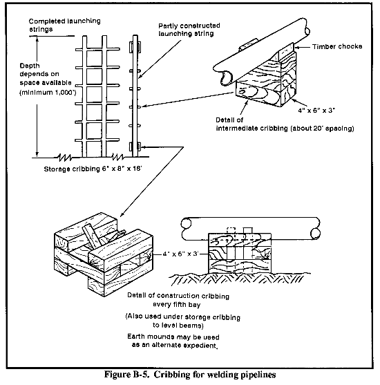
(1) Position Welding. Position welding is the standard method for welding military pipelines and is particularly applicable to welding sags and overbends or making tie-ins. With this method, the pipe remains stationary, and the welder works around the circumference of the pipe. Therefore, the pipe must have a minimum 16-inch clearance (see Figure B-5). When making tie-ins in a trench, dig a bell hole so that the welder can get at the underside of the pipe without undue restraint.
(2) Roll Welding. With this method, the pipe is rotated so that the welding is always done at or near top center. Although seldom used in welding military pipelines, this method is sometimes more expedient in welding short strings of line, such as road crossings or manifold systems, or for lines inside of fire walls at tank farms.
b. Procedures.
(1) Cleaning. Just before the welding operation, clean the pipe-end bevels of all foreign matter. Do this by filing or brushing or by using portable, motor-driven brushes or grinders. Just before cleaning the pipe-end bevels, swab the pipe to remove any excess dirt, sticks, stones, small animals, or reptiles. If the random length pipe sections are longer than the standard swabbing snakes, lengthen the snakes a few feet by taping or wiring a piece of wire rope on the forward end of the snake. (For double-random sections, make a snake by overlapping and taping two snakes together.)
(2) Rebeveling and Cutting to Length. During handling, the pipe bevel or the end of the pipe may be damaged. Sometimes you may have to cut and bevel a piece of pipe to a certain length. Use an oxyacetylene pipe cutting and beveling machine to rebevel or to cut and bevel. Then use a bevel grinding machine to clean the bevel of slag. Both machines are in the welded pipeline construction tool set.
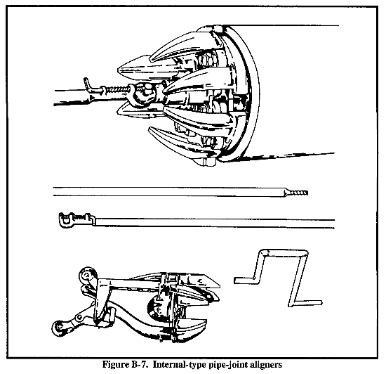
(3) Aligning Clamps. Producing a satisfactory pipe-joint weld requires exact alignment of the pipe joint. Two types of pipe-joint aligners are available:
- Tipton-type, external, pipe-joint aligning clamps for 4-, 6-, and 8-inch pipe sizes are common to all welded petroleum pipeline construction (see Figure B-6). The clamp aligns the pipe joint externally, eliminates almost all out-of-roundness of the pipe ends, and holds the pipe joints in a longitudinal position until at least 50 percent of the stringer bead (stringer pass) is completed.
- Internal-type pipe-joint aligners (Figure B-7) produce the required alignment and eliminate the requirement for preliminary tack welds necessary with the external-type lineup clamps.
c. Standards.
(1) Use beveled pipe for welded sections of military pipeline. This pipe is furnished with carefully squared ends and beveled edges so that, when placed with ends about 1/16-inch apart, there is a groove all the way around the joint where the welding metal is applied. The groove angle is about 75 degrees for pipe with a wall thickness of 1/4 inch or less; for pipe with a wall thickness of more than 1/4 inch, the groove angle is about 60 degrees (Figure B-8).
(2) Use reverse polarity (the electrode is positive and the work is negative), if you use shielded arc electrodes. Do not start two welding beads (passes) at the same point on the circumference of the joint. When you complete one bead, remove all scale or slag from the bead, undercut, and groove with a powered wire brush and an ice pick before welding the next bead. Adjust the welding amperage and the arc travel speed accordingly to produce the following welds:
- Filler pass - should be about l/8-inch thick. Run enough beads to provide the reinforcements required for the completed weld.
- Stringer pass - should provide complete penetration, filling the bottom of the groove with weld metal. Penetration should not be so great as to burn through and blow the weld puddle into the pipe.
- Finish (or cover) pass - should be about 1/8-inch greater that the original groove. Thoroughly fuse the weld metal in each bead to the parent metal of the pipe so it provides a reinforcement of not less than 1/32-inch or more than 1/16-inch above the pipe surface. Thoroughly brush and clean the finished weld.
(3) Remove the full section containing lamination or split ends if you discover such defects during the welding process. Do not use this section of pipe until you repair or remove the defect.
(4) Rebevel the pipe if the ends are damaged during handling so that you cannot get a satisfactory welding contact. Use a beveling machine on all cuts on ends of line pipe for welding. Freehand bevel cuts of line pipe in preparation for welding are not permitted. After rebeveling, grind the bevel with a bevel grinding machine.
d. Precautions. Coated electrodes are subject to deterioration from moisture absorption. Store electrodes in unopened original containers, and protect opened containers from excessive moisture changes. In handling electrodes, avoid damage to the coating. Do not use electrodes that show signs of deterioration or damage.
Do not weld when the quality of the completed weld may be impaired by the prevailing weather conditions, which include airborne moisture, blowing sands, and high winds. Use windshields when practicable, and use the umbrella (included in the welder's supplemental pipeline construction kit) when necessary. In very cold weather (below freezing), preheat the pipe before welding it. If you have to leave an incomplete pipeline section overnight, close the open ends by tack-welding plates or caps so foreign matter or vermin cannot enter.
e. Tie-Ins. During most laying operations, you may have unconnected sections of the line. Welding these sections together is known as tie-ins. These unwelded sections usually occur because of the following:
- The section of line beneath a road or railroad is not installed by the welding crew.
- The line is not completed at river crossings.
- Crew members would like to have a free section to work on coated lines (lines being prepared for burying) without interfering with welding operations.
- The line is left open for swabbing.
f. Buried Pipe. Welded, standard-weight, steel API STD5L pipe is the only type you can bury. Do not use lightweight tubing under any circumstance. Bury pipeline where the line is susceptible to damage if left exposed or where breaks will create a fire hazard to essential military or civilian activity. For example, bury the line--
- At river-crossing approaches, especially where the possibility of flooding could wash away unburied line.
- At road crossings where the line cannot run through existing or improvised culverts.
- In airfield distribution systems.
- In areas where the route passes through cities or other populated areas.
- In cultivated areas.
- In areas where the pipe is on the shoulders of main supply routes. If not buried, this pipe could be broken or crushed by vehicles that go off the road surface.
When planning for buried pipe, contact local civil authorities, utility companies, and commercial organizations through whose property the line will pass. They will advise you of any buried systems or facilities, such as installed cathodic protection systems, that you must avoid.
(1) Construction Standards.
(a) Depth. Bury the pipe deep enough to furnish at least a 2-foot cover of earth as protection against the weight of trucks, tanks, and other heavy vehicles or aircraft that may pass over it. In general, the larger the diameter of pipe, the deeper it should be buried. A depth of 3 feet is preferable for 8- or 12-inch pipe.
(b) Minimum clearance with underground structures. Buried pipelines often pass close to or cross other buried structures, such as electrical cables, sewage systems, drain tiles, poles, and anchors for poles. Lay the pipeline so other structures will not be damaged during construction or later through settlement, breakage, or movement of the pipeline. In civilian construction, the pipeline usually passes under all other pipelines and similar structures that it crosses. This practice permits work on other utilities without interfering with the pipeline. It also ensures that when the line settles, its weight will not damage other structures. Usually, a clearance of not less than 4 inches (12 inches for metallic structures) is desirable. However, the type of structure will determine the clearance requirements and how to deal with the problem. Such problems could be avoided if, during the planning stage, a route is chosen that avoids interfering structures.
(c) Corrosion prevention. Buried pipe is subject to external corrosion more than pipe exposed to the air. Regular-weight pipe lasts up to about 2 years when buried in most soils. To inhibit corrosion, coat the pipe with corrosion-resistant materials, such as coal-tar enamel or petroleum materials, and apply protective wrappings.
(d) Cathodic protection. External corrosive damage to buried pipe is similar to the chemical generation of electricity in a storage battery. A buried pipeline could contain all of the elements of a battery, which are two materials that have differing electrochemical potentials, connected electrically, and immersed in an electrolyte (the moisture in the ground in which the pipe is buried with its dissolved salts). One material, the anode, is the focus of corrosion.
Cathodic protection is the measures taken to stop the flow of direct electrical currents from the pipeline to and through the soil in which it is buried. This is done by impressing current from external sources through the soil to the pipeline so that the pipe becomes the cathode. Several methods and combinations of methods are used to do this; however, this manual will not address any method, since cathodic protection is not ordinarily installed for military pipelines. Pipelines in captured or allied territory may be equipped with cathodic protective devices and wiring systems. Do not alter or repair these systems without expert advice. Incorrect application of the principles of cathodic protection can do more harm.
(2) Construction Procedures. When burying pipe--
- Dig the trench.
- Assemble the pipe.
- Apply the protective coating.
- Lower the pipe into the trench.
- Back fill the trench.
(a) Precautions in trenching. Before burying a pipeline, a thorough reconnaissance of the route is necessary. The purpose is to locate underground utility and communications lines, drain ditches, irrigation canals and other watercourses, and similar obstacles that will require special treatment. In ditching for a buried line, you can continue the ditch at normal depths across such obstacles when there is no danger of damage to the pipe from accumulated driftwood, washouts, or falling trees. This procedure eliminates the deeper ditch across the bottom of a stream and the pipe bending needed to follow the contour of the deeper part of the ditch. In even terrain, excavate only a length of trench that you can back fill the same day.
(b) Trenching methods. The most efficient tool for digging pipeline trenches is the SEE (Figure 1-4). Pipe is buried in trenches about 20 inches wide with at least 2 feet of cover. If machines are not available, the ditching will have to be done by hand. The trench, when completed, should provide a smooth supporting surface for the pipe. The trench should be deeper between points selected for sags and over bends so the pipeline is as straight as possible. Where this is not possible, the line should be bent with a pipelayer equipped with a bending shoe. Rough spots or irregularities in the bottom of the trench can often be filled in with loose material. The finished trench should be free of clods, rocks, tree roots, and other hard objects.
(c) Assembling pipe. Place the pipe on cribbing alongside the trench for welding assembly.
(d) Coating and wrapping. Remove dirt, paint blisters, and mill scale from the outside of the pipe before applying protective coating. Apply the coating, such as coal-tar or asphalt enamel, with brushes. A second method of applying the coating is with a two-man crew, using the following procedures:
- Pour the coating on top of the pipe and spread it by drawing the pipe back and forth using a belt sling passed under the pipe.
- Wrap a reinforcing mat (fiberglass) around the pipe and imbed it in the coating.
- Apply a protective outer wrap of felt or heavy wrapping paper. As an expedient, you may use burlap or other coarse fabric impregnated with protective material.
- Wait for the pipe to be lifted with belting slings (pipelayer on large pipe sizes) as you reach the cribbing to complete the coating process.
(e) Lowering pipe into the trench. After the protective coating has hardened, pipelayers, equipped with belt-type slings, lower the pipe into the trench. Steel pipe contracts about 0.8 inch per 100 feet for a temperature drop of 100° F. The elasticity of welded pipe offsets this change, and the effect of expansion and contraction of a buried military pipeline is not too significant. The sags placed in the line to follow the contour of the trench must rest on the bottom. Side bends should rest on the bottom of the trench and against the outside wall of the curve.
(f) Filling the trench. If practicable, bury the line during the coolest part of the day while the pipe is contracted. Back fill immediately after lowering in the pipeline so that the pipe or its protective coating will not be damaged. Use only good, loose soil that is free from trash, debris, rocks, or clods as the first layer that you place over the line. Cover the pipe with not less than 4 inches of this type of backfill. If this type is not available along the right-of-way, it should be hauled in from other locations. Use expedient equipment such as angle dozers, bulldozers, or graders to complete the backfill. The crawler-mounted, side-boom backfilled is the most efficient piece of backfilling equipment. When backfilling, be careful not to disturb the coating and wrapping. Do not drop heavy stones on the pipe or allow such stones to roll into the trench against the pipe. Use the following procedures, where applicable:
- Take extra precautions to prevent damage to the pipe and coating in rocky areas. One method is to provide a traveling shield or lizard that is pulled ahead of the backfilling machine to absorb the impact of the earth being placed in the trench over the pipe. You can field-fabricate this traveling shield using heavy belting fabric or a piece of shaped metal. Shape it so that the shield will protect the pipe and coating as it is pulled along the ditch.
- Place sandbag dams at intervals in the trench on steep slopes to prevent the uncompacted trench from becoming a sluice for rainwater runoff.
- Make sure the backfill is dry and placed quickly in areas where you encounter considerable groundwater. The pipeline, because of its positive buoyancy, could float and even rise up out of the trench in wet, sloppy backfill.
(3) Testing. You can test for leaky joints before or after lowering the line into the ditch. However, try to test for leaks before backfilling, since leaks are easier to locate.
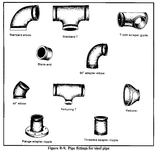
g. Bending Pipe. To change direction or angle in welded pipelines, you can use the fittings shown in Figure B-9. You can make some smaller angle changes by bending the pipe. However, with the type of scrapers presently in military use, the radius of pipe bends must be at least eight times the diameter of the pipe or the scrapers will not pass. (Use more gradual bends when possible.) Pressure loss due to friction increase in the pipe is negligible unless an unusually large number of joints are used. Cold bends and wrinkle bends are the two methods normally used in the field.
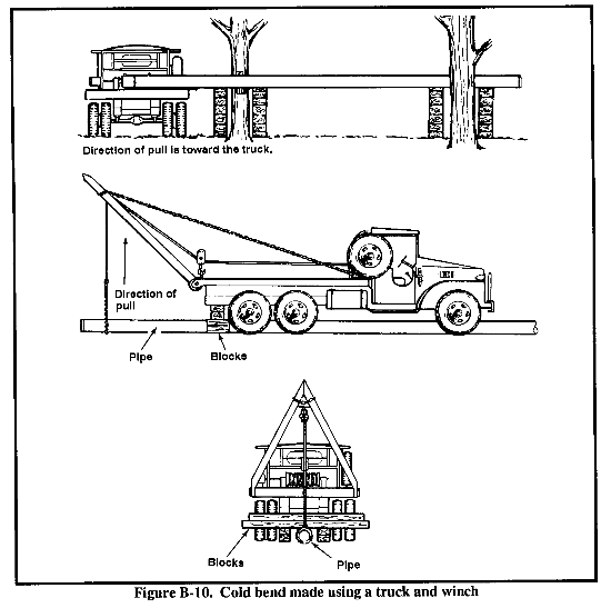
(1) Cold Bends. For cold bends (Figure B-10), the pipe joint is pulled until stressed beyond the yield point of the material, thus causing a permanent set. Do not use this method on thin-walled military tubing. The tubing sections will always buckle before you can attain a slight bend. Hydraulic or mechanical machines provide the simplest method for creating such pipe bends. Use them whenever possible. If these machines are not available, you can bend pipe using any expedient method such as the following:
- Tactical vehicles or simple block and tackle providing bending power.
- Wood cribbing, A-frames, or chassis-mounted shoes fabricated of pipe scraps serving as fulcrums.
- Gin poles or A-frames providing support for vertical bends.
Use the following equation to determine the pipe lengths for cold bends:
L= RD (0.017) + T
where--
L = length of bend, in inches.
R = radius of bend (to centerline of pipe), not less than 8 times the nominal pipe diameter, in inches.
D = number of degrees in the bend.
T = total length of tangents on each end of bend, in inches.
|
Example Find the minimum length of 8-inch pipe required to make a 90-degree bend having l-foot tangents on each end. R = 64 inches (8 inches x 8)D = 90 degrees T = 24 inches (2 x 12 inches) L = 121.92 or 122 inches (64 x 90 x 0.017+ 24 = 97.9+ 24) |
(2) Wrinkle Bends (Figure B-11). Use an acetylene torch to heat the pipe (not tubing) to produce an area of relative weakness. If done correctly, the bent portion of the pipe will have an outwardly projecting wrinkle. The method requires a skilled welder and a large amount of time and materials. (Wrinkle bending has become less popular because of specialized, reliable, cold-bending machines.) Use the following procedures for this method:
(b) Construct a fulcrum using pipe sections driven into the ground for horizontal bending, or use a field-fabricated shoe welded to a truck chassis for vertical bends. You could conceivably use a section of larger diameter pipe, properly staked or weighted, as a fulcrum.
(c) Use items such as heavy-duty, manual screw jacks; block and tackle; and power winches for an easily controllable bending force.
(d) Construct a gin pole or A-frame for supporting pipe on vertical bends or cribbing for horizontal bends.
(e) Heat a narrow band of the pipe (about two-thirds to three-quarters around the pipe's circumference) with a torch to a bright cherry-red color close to the desired bend.
(f) Bend the pipe inward on the heated portion to form a wrinkle in the pipe wall. Limit the bend to no more than 5 degrees.
(g) Space each successive bend one pipe diameter apart.
To determine length of pipe required for winkle-bending degree of bend, use the following equation:
| L | = (degree of bend) | - 1 x nominal pipe diameter + T |
| 5° |
where--
L = length of pipe required, in inches.
T = total length of tangents on each end of bend, in inches.
|
Example Find the length of 8-inch pipe required to make a 90-degree bend having l-foot tangents on each end of the bend. T = 24 inches (2 x 12) L = 160 inches ((90/5 -1) x 8 + 24 = 17 x 8 + 24 = 136 + 24) |
(3) Underwater Crossings. Use a 2-foot minimum cover at all underwater crossings, regardless of stream-bed conditions. Two feet is sufficient where crossings are made in solid rock. However, increase the cover as the streambed changes from rock to sand. (A 6-foot cover is necessary in a sandy, shallow river.) Measure the cover below the lowest point in the streambed.
Many rivers carry more water underground in their broad, sandy valleys than is carried as surface water. These rivers are likely to scour badly during flood stage. If this condition exists, lay the line flat across the valley from the fixed low point so that future channel changes and scouring will not affect the crossing. A stream with low banks in a wide, sandy valley will be subject to overflow and scour across the entire valley. If this condition exists, place the line below scour depth all the way across the area subject to high water. If possible, place the crossing in a long, straight reach of the stream, as the banks are less likely to cut and expose the line.
Crossings at bends or narrows will be subject to stress or damage from floods, water velocity, and scouring of the streambed. Do not provide an upstream or downstream bow in the line. It is difficult to pull an accurate bow in a pipeline. Unless you properly bury the pipeline, it might become a swinging line. Driftwood lodging against a swinging line may exert a force great enough to pull the line apart. Bury the line deep enough and far back from the water's edge so that fast flood waters will not uncover and damage the line.
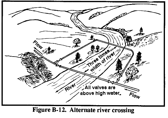
Examine the crossing site closely to determine the height of previous flood waters. The pipeline placed in the riverbed should be flat. If practicable, excavate the banks so that you will not need sags or overbends. Place block valves above the highest watermark on each side of the river. As soon as possible, construct an alternate crossing several hundred yards upstream or downstream to provide uninterrupted flow if the major crossing is damaged (Figure B-12). Connect this alternate crossing line to the main crossing at a point well back from any possible flood zone so that the block valves can be located and safely reached if necessary.
(a) Preparing the bottom (ditching). The method of excavating the ditch for a river crossing will depend on soil conditions and available equipment. Sand may be wet-excavated by means of a dredge or dragline, or it may be dewatered with well points and dry-excavated with a dragline. Occasionally, you can use a sand pump to remove sand or silt from underneath a line to lower it into place or to prepare the ditch just ahead of the line as it is launched. You can remove rock (and mud) by drilling and shooting through water, if necessary.
(b) Assembly and launching. Submerged pipeline river crossings will be of welded construction and only heavy weight submarine line pipe. Assembly and installation of major crossings are the same as for submarine pipelines except that the triple-drum (pulling) winch and the holdback winch would be on opposite sides of the river. Place the pulling winch on the far side and the holdback winch on the near side. Use tractor or truck winches for smaller crossings. As soon as the pipeline has been pulled into place, pump it full of water to displace the air in the pipe and increase the line's in-place weight.
(c) Backfill. Pay particular attention to the backfill on the banks of streams. A soft backfill in a wide right-of-way cut is likely to slide into the stream during a flood or to be carried away by the current. In either case, future floods will erode the bank and expose the line. Firmly tamp the backfill and reinforce it with sacked earth, rip-rap, or other similar materials, if necessary. Backfill the streambed ditch with crushed rock, if practicable. Backfill the streambed ditch carefully if you use earth. Use a clamshell to lower the earth to the bottom of the ditch; place the backfill directly on top of the pipeline. Do this operation quickly to minimize mixing the earth and water. Since mud has a higher specific gravity than water, the line is buoyed up more than it is by water. The drier the backfill, the better.
h. Welding Repairs. Welding is used to make temporary and permanent repairs on welded pipelines. Welding can be extremely dangerous. It should be done only in an emergency by a skilled welder. The commanding officer of the using organization must approve any welding operation. The welder should use only electric arc welding, be supervised, and weld according to the guidelines in TM 9-237. The safety officer should issue a permit to weld; the permit should be posted in the welding area. Once a welder has permission to weld, he should--
- Move fire-fighting equipment into the area.
- Wear clothing and shoes that protect him from the fuel and the welding operations.
- Use an explosimeter to find out if fuel vapors are in the welding area. The readings must be in the safe zone before welding.
- Use the right size and type of electrodes and not worn electrodes.
- Pack the line with moving fuel to displace the vapors and to carry heat away from the weld.
- Keep in constant contact with the pumping-station operator. He must stop welding if pumping operations stop or if pressure in the line drops.
i. Pipeline Painting. Paint coupled steel pipeline with enamel to prevent rusting and to reflect heat. (The first coat is applied at the factory.) Paint identification markings on pipe sections after putting the pipe into operation. Pipelines are checked often for chipped and flaking paint to make sure that the protective coating and the markings do not wear away.
(1) Protective Coating. To spot paint the protecting coating--
- Use a wire brush and paint scraper to remove flaking paint and rust.
- Sand the surface down to the bare metal.
- Wipe the surface clean.
- Paint with red lead primer (DOD-P-17545). Let the primer dry.
- Paint the primed areas with rust-inhibiting, semigloss enamel (Federal Specifications TT-E-485F). Use the natural color to reflect heat unless the pipeline has been painted with camouflage colors.
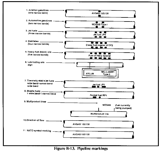
(2) Markings. Check the markings on the pipeline and paint them if they cannot be read easily. The markings (Figure B-13), which are painted on the line near valves, should conform to the guidelines in AR 385-80 and MIL-STD-161. Some marking guidelines are--
- Bands of yellow paint symbolize caution. Yellow bands are used to warn of the presence of flammable materials.
- The number of bands that appear around a pipeline identify the fuel that is pumped through the pipeline.
- A sign with a black background and white letters on each pipeline that identifies the fuel.
- A yellow arrow shows the direction in which the fuel is flowing in the pipeline.
B-5. Welded Pipelines. Welded pipelines should be buried. However, if a leak occurs, it could go unnoticed until it is large enough to affect the fuel pressure in the pipeline. A sudden drop in pressure from one pumping station to the next could mean a leak in that section of the line. Comparing the amount of fuel pumped through meters at various locations could narrow down the area. A drop in throughput from one meter to the next indicates a leak between the meters. When the general area of the leak is determined, the line is laid bare so it can be repaired. Remove the dirt around the pipeline until you find the exact location of the leak. Dig out the area around the leak completely, allowing for working room and a clear escape route from the trench.
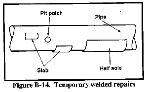
a. Temporary Repairs. Use clamps or weld temporary repairs. There are three types of temporary repairs on pipe sections you can do by welding (Figure B-14). The type of welding repair will depend on the size of the damaged area.
(1) Small Pits. Small pits in the outside wall of a pipe section are spot-welded so that the pits are flush with the outside of a pipe. This repair is called pit patching. Use this method only when the pipe is in good condition or if there are a few rust spots. When making a rust repair--
- Clean the rusted area down to bare metal.
- Use a pit gauge to measure the pits.
- Fill in the pits that measure less than one half the thickness of the pipe.
- Maintain flow in the pipeline to carry away the heat.
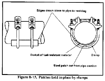
(2) Areas Less Than One Half of the Pipe. You can repair rust areas that are on less than one half of the pipe circumference by welding precut pieces of pipe over the damaged areas. The patches may vary in size from small slabs to half soles or half wraps that cover half of the pipe. When making this repair--
- Cut a patch from a pipe section slightly larger in diameter than the damaged one.
- Reshape the patch so that it fits snugly against the pipe.
- Clean the rusted area down to the bare metal.
- Hold the patch in place with steel leak clamps (Figure B-15).
- Weld the patch in place on all sides and remove the clamps.
- Maintain flow in the pipeline to carry away the heat.
(3) Areas More Than One Half of the Pipe. You can repair pipe that is rusted in large areas on the top and on the bottom by surrounding the damaged line with a casing. To make this repair--
- Cut a casing, from new pipe, slightly larger in diameter than the damaged pipe.
- Cut the casing in half along the entire length.
- Wrap the two halves around the damaged pipe.
- Hold the pieces in place with clamps and weld them together.
- Run welding bead around the casing at each end.
- Maintain flow in the pipeline to carry away the heat.
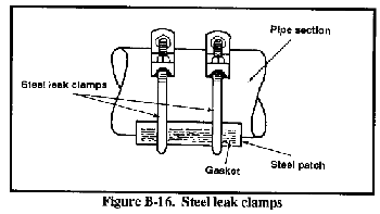
(4) Clamp Repairs. You can temporarily repair small pit leaks with steel leak clamps (Figure B-16). Using these clamps is a stopgap measure. The repaired pipe should be replaced as soon as possible. To mount a steel leak clamp--
- Cover the leak with a cone-shaped or a flat gasket. Make sure the gasket is made of fuel-resistant material.
- Cut a steel patch to cover the gasket. Curve the patch to match the curve of the pipeline.
- Hold the gasket and the steel patch in place and cover them with steel leak clamps.
- Put the bolts in the clamp, attach the nuts, and tighten the nuts.
b. Permanent Repairs. Permanent welding repairs are made by removing damaged pipe and welding new pipe in place. The temporary measures described above should be replaced with permanently welded pipe as soon as possible. Permanent welding repairs are made with and without the use of a bypass. The method used depends on whether or not the repair is an emergency.
(1) Emergency Repairs. If a large leak occurs that cannot be repaired with clamps, pumping operations are stopped and the commanding officer and the safety officer are notified. The leaking section is then replaced as quickly as possible without taking the time to construct a bypass. Such an emergency pipe change can be dangerous because of escaping fuel and fuel vapors. You must follow all safety rules. Once you locate the leak--
(a) Move fire-fighting equipment into the area.
(b) Wear proper clothing and shoes for protection from spills and welding operations.
(c) Close gate valves on each side of the leak to limit the amount of fuel flowing to the leak.
(d) Move anything that could cause a spark out of the area.
(e) Drain any fuel still in the damaged section of pipe into drums or tank vehicles. Use a suction pump to remove fuel that may have collected in the trench.
(f) Cover spilled fuel and fuel-soaked ground with fire-retarding foam.
(g) Let vapors be carried away or dispersed in the air.
(e) Use an explosimeter to find out if there are fuel vapors left in the area of the leak. Check inside the pipe. Displace fuel vapors with carbon dioxide or nitrogen (both are available in fire-fighting equipment). Make repairs only when the readings on the explosimeter are in the safe zone.
(f) Dig out a trench so personnel can work around and under the section of pipe. Make sure there is an escape route.
(g) Cut out the section of damaged pipe with mechanical cutters and move the damaged pipe out of the way.
(h) Swab out the pipe ends and clean the pipe end bevels with a wire brush and file.
(i) Move the new section of pipe into position and align it with the old pipe.
(j) Hold the new section in place with clamps and weld the sections together. (Remember that only skilled welders may do the welding.)
(k) Open the gate valves slowly to let pressure and fuel back into line.
(l) Start pumping operations.
(m) Purge the entrained air from the pipeline.
(n) Check for leaks.
(o) Coat bare areas of pipe with coal-tar enamel. Wrap the pipe with a layer of felt.
(p) Bury the pipeline.
(2) Nonemergency Repairs. If a small leak occurs, stop the leak with a steel leak clamp until the pipe can be replaced. Spot-welded and patched pipe should also be replaced as soon as possible. Get permission to weld from the commanding officer of the using organization and a permit to weld from the safety officer. Since this is not an emergency repair, you can build a bypass line, which will carry fuel around the repair area. Using a bypass line means that pumping operations can go on while you replace the damaged section. Be careful so that fuel vapors will not ignite. Wear proper clothing and shoes for protection from fuel spills and welding operations. Move fire-fighting equipment into the area and post the welding permit. To replace a section of welded pipe, using a bypass line--
(a) Dig out the area around the pipeline and provide space for the bypass line.
(b) Make sure the line is packed with fuel to displace vapors and to carry heat away from the weld. Keep in contact with the pumping-station operator to make sure that pressure in line does not drop.
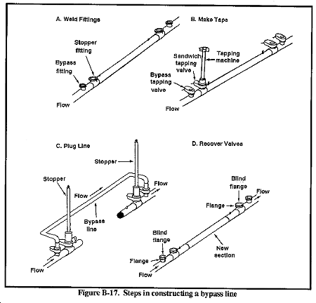
(c) Weld a bypass fitting and a stopper fitting on each side of the pipe section you are replacing (Figure B-17, A). (Remember, only skilled welders may weld.)
(d) Bolt a bypass-tapping valve on each bypass-fitting and a sandwich-tapping valve on each stopper fitting.
(e) Attach a tapping machine to the bypass valves, tap through the valves, close the valves, and remove the tapping machine.
(f) Construct a bypass line and attach it to the pipeline at the bypass-tapping valves.
(g) Use the tapping machine to cut into pipe at the sandwich-tapping valve (Figure B-17, B).
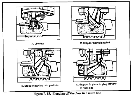
(h) Put the stoppers in place and plug off the flow in the main line. This forces the fuel to flow into the bypass line (Figure B-17, C, and Figure B-18).
(i) Tap or break the line in the repair section and drain the fuel into drums.
(j) Cut out the damaged section with mechanical cutters and move it out of the way.
(k) Allow time for the fuel vapors to be carried away or dispersed in air.
(l) Swab out the ends of the old section of pipe.
(m) Use an explosimeter to find out if fuel vapors are left in the repair area. Do not weld until the readings are in the safe zone.
(n) Move the new section of pipe into position and align it with the old pipe.
(o) Clean the pipe-end bevels with a wire brush and file.
(p) Hold the new section in place with clamps and weld the pipe sections together.
(q) Stop pumping operations to reduce pressure in the line to zero.
(r) Take out the stoppers and remove the sandwich-tapping valves, the bypass line, and the bypass-tapping valve.
(s) Bolt blind flanges in place to cover the bypass and stopper fittings (Figure B-17, C and D).
(t) Start pumping operations.
(u) Purge the entrained air from the pipeline.
(v) Check for leaks.
(w) Coat bare areas of pipe with coal-tar enamel. Wrap the pipe with layer of fiberglass and a layer of felt.
(x) Bury the pipe and fill in any area dug out for the bypass.
(3) Clamp Repairs. There are two kinds of clamps you can use to repair minor damage to a pipeline permanently. Both of the clamps are made of stainless steel and require the use of fuel-resistant gaskets.
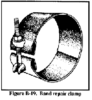
(a) Band repair clamps. Use this clamp (Figure B-19) to repair a small leak. To mount--
- Cover the leak with a fuel-resistant gasket.
- Wrap the clamp around the pipeline, taking care to cover the gasket.
- Put the bolt in the clamp, place a nut on the bolt, and tighten the nut.
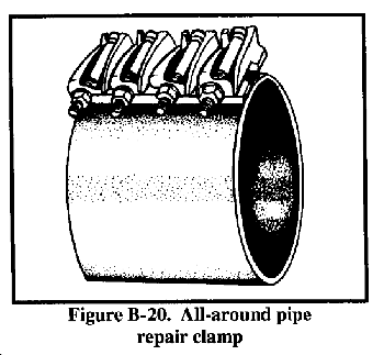
(b) All-around pipe repair clamp. Use this clamp (Figure B-20) to repair pitted areas and breaks that run completely around the pipeline. To mount the clamp--
- Cover the rusted area or break with a fuel-resistant gasket. You may have to use gasket material to cut a gasket large enough to fit.
- Wrap the clamp around the pipe, covering the gasket.
- Put the bolts in the clamp, place the nuts on bobs, and tighten the nuts.
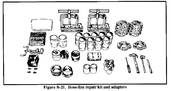
B-6. Hose Lines. Patching equipment is provided for repairing seeping or spraying leaks that may develop through the wall of the hose during testing and use (Figure B-21). While the hose is still under operating pressure, cover the leak and an area from 4 to 6 inches on each side with one spiral wrap of 2-inch-wide neoprene rubber tape and two spiral wraps of 2-inch polyvinyl tape. Apply the tape wraps with as much tension as you can.
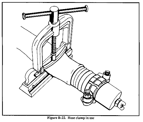
If a hose develops excessive leakage from a split or puncture, repair it by cutting out the defective area and rejoining the cut ends with two coupling sleeves and a coupling. Install hose clamps (included in the hose-repair kit) on each side of the leak far enough to reach an undamaged area (Figure B-22). Use rubber cement as a lubricant so you can insert the sleeves into the hose easier. Using a special banding tool, wrap stainless steel bands around the exterior of the hose end and over the sleeve to firmly join the hose to the sleeve. You can use hand tools (included in the kit) to help install the sleeves. After you finish attaching the repaired sleeves, bring together the grooved ends of the sleeves and connect them with lightweight, groove-type couplings.
|
NEWSLETTER
|
| Join the GlobalSecurity.org mailing list |
|
|
|


