| Chapter Two. Equipment |
2-1. The Army Facilities Components System (AFCS). The AFCS consists of Technical Manuals (TMs) 5-301, 5-302, 5-303, and 5-304 that makeup a system for rapidly determining the Class IV materials, layout, and construction effort required. (TM 5-304 explains the terminology used in AFCS, such as installations that are made up of facilities which are made up of items.)
2-2. Aluminum Pipeline Facilities. Figure 2-1 shows the packaging symbols for the IPDS.
a. 5-Mile Pipline Set. This set consists of the pipes, couplings, and gaskets needed to build 5 miles of pipeline. The set also includes gate valves, check valves, vent assemblies, elbows, pipeline anchors, culvert materials, overcouplings, and repair clamps needed for a 5-mile section of pipe.
b. Mainline Pumping-Station Set. This set consists of pumps, gate valves, check-valve launchers, receivers, strainers, light sets, and pump shelters needed to construct a standard, mainline pumping station. Most mainline pumping-station kits include two pumping units to facilitate a 24-hour operation. Each pumping-station set differs slightly in its capabilities and component listings.
c. Pipeline Suspension-Bridge Set. Pipeline suspension-bridge assemblies are available in 100-, 200-, and 400-foot kits. A set consists of towers; guy wires; deadman anchors; main cables, suspenders, and cross bearers; staging board; tension cables; wind guys; and hand rope needed to construct the bridge. No special tools are required.
2-3. Pipeline Items.
a. Pipes. The different types of pipe used to construct military pipelines are coupled aluminum IPDS pipe, coupled lightweight steel pipe, and welded or coupled standard-weight pipe. The aluminum IPDS pipe--
- Has replaced the lightweight steel tubing.
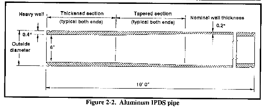
- Comes in 19-foot sections with a 6-inch nominal inside diameter (ID).
- Is modified single-grooved at each end.
- Is connected with a snap-joint coupling.
- Is designed to be surface-laid, not buried, because of coupling and strength limitations.
See Table 2-1 for weight, dimensions, and strength of IPDS pipe and Figure 2-2 for a sample of the IPDS pipe.
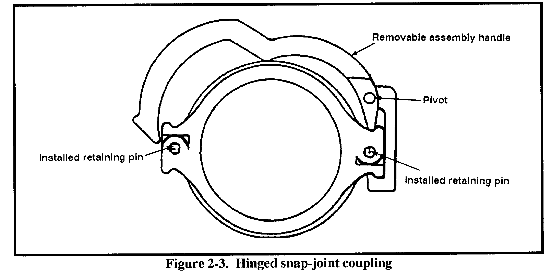
b. Aluminum Pipe Coupling. The hinged snap-joint coupling, which is standard for single-grooved aluminum pipe, is available with either a one-piece separate gasket or a two-piece integral gasket (Figure 2-3). The coupling consists of two sections that are hinged together and a pin for closing the coupling over the pipe ends. The coupling and gasket are designed to seal under pressure and vacuum. The hinged coupling allows for a 2 percent deflection between joints and a maximum allowable working pressure (MAWP) of 740 psi.
c. Pipeline Valves. These valves are used in pipelines to cut off, control, and direct the fuel flow in the line.
(1) Gate Valve. This valve has a gate (disc or wedge) that is opened or closed to control fuel flow. A gate valve is used to stop flow at the tank or in the pipeline. Valves are located along the pipeline (one-mile intervals), at the bottom of long slopes, and on both sides of a stream or road crossing, so that when leaks occur, the valves can be closed to prevent excessive fuel loss and allow for repairs. A gate valve--
- Is supplied with threaded ends or with flanged ends and flange-to-groove adapters or is made up in 20-foot gate-valve sections.
- Must open to the full diameter of the pipe if used in the line and at the entrance and exit of manifold scraper stations.
- Is set, when in use, at FULLY OPEN or FULLY CLOSED, since it is not suitable for throttling the fuel flow. If the gate protrudes partially into the pipe, it may be so abraded by dirt and scale in the fuel flow that it will no longer serve as a tight valve when closed.
- Is either a rising- or nonrising-stem type with an outside screw and yoke.
In the rising-stem type (Figure 2-4), the upper part of the stem is threaded. A nut, fastened to the handwheel and held in the yoke by thrust collars, moves the stem as the handwheel is turned. Determining if a rising-stem valve is open or shut is easy. Therefore, this type of valve is used in pipeline station manifolds and similar locations where it is necessary to identify quickly if a valve is open or closed. However, a rising-stem valve requires more space and is more susceptible to tampering or sabotage than the nonrising type. In manifold systems, a rising-stem valve is included in gate valve sections with an overall length of 36 inches.
In the nonrising-stem valve (Figure 2-5), the lower end of the stem is threaded; it screws into the disk. The disk moves up or down while a thrust collar keeps the stem in place. In both valve types, the line-closing element is made up of two disks separated by a split wedge. As the stem is turned to close the valve, the disks move down until they are directly opposite the port.
The action of the beveled surfaces between the two disks forces the disks apart squarely against their seal and eliminates sliding action on the valve seal.
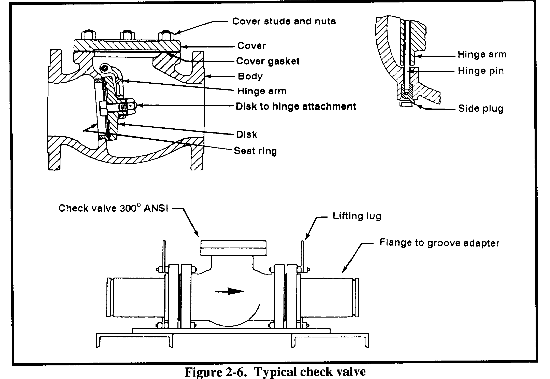
(2) Check Valve. A check valve is constructed so the fuel flows only one way. The valve has a hinged disk or clapper that the fuel pushes when the flow is in the correct direction. When the flow stops and back pressure develops, the clapper is pushed against its seat, stopping back flow. Figure 2-6 shows a typical check valve. A check valve is often used at the foot of an upgrade slope in lieu of a gate valve. So line scrapers can pass, a check valve must be opened to the full diameter of the pipe when used in the line between pumping stations.
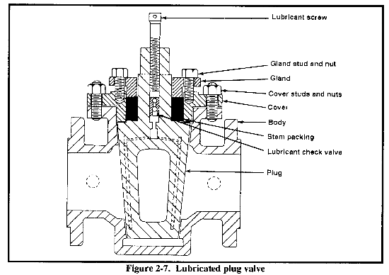
(3) Plug Valve. This valve has a revolving plug with an opening so that fuel flows when the opening is aligned with the pipe. Figure 2-7 shows the structure of a typical lubricated plug valve. A plug valve opens or closes with a quarter turn of the plug. When the wrench is in place, it is easy to determine if the valve is open or closed. A plug valve is used in a tank farm manifold and on launchers and receivers where quick and positive closing of the valves is essential.
A plug-valve assembly, with an overall length of 36 inches, is included in a manifold assembly. If a pumping-station manifold is assembled in the field using available material and a rising-stem gate valve is not available, a plug valve may be substituted. However, some plug valves (not in the AFCS) have openings equal to the full diameter of the pipe, while others do not. The valves that do not have full openings cannot be used in sections of the pipeline or manifold that require pipeline scrapers to pass.
Since the plug fits the valve seat snugly to close the line completely, a great deal of friction results. The plug valve is lubricated with a viscous lubricant that is forced into-all parts of the valve by compressing the screw on top of the valve. The primary function of the lubricant is to jack or raise the plug off the seat and to seal the space between the plug and the seat after the plug has been turned and seats itself. This lubricant is insoluble in petroleum products but is soluble in water. Relubricate the valve whenever water passes through it. Make sure that the thick lubricant is free of dirt, grit, and other foreign matter that could obstruct lubricating channels and damage the valve seat and face.
(4) Pressure-Reducing Valve. This valve is a diaphragm-activated, spring-loaded regulator. When a pipeline is on a long, downgrade slope that is steeper than the hydraulic gradient of the line permits, the valve is spring-loaded to close. This should prevent excessive line pressure from building up when flow is stopped. Pressure-reduction regulators are included in standard pressure reducing stations.
(5) Thermal-Relief Valve. This valve is used to relieve pressure buildup within the pipeline from the thermal expansion of the product within the pipeline. Under blocked-in conditions, overpressure can result in damage to the equipment, possible personal injury, and fire. If properly installed, the thermal-relief valve discharges small quantities of fuel through the drain hose to relieve the pipeline of pressure buildup. Thermal-relief valves are set 10 percent above the maximum pipeline pressure. The valve is located on the launcher and receiver assembly. The thermal-relief valve should be removed, serviced, and tested routinely or every six months. Immediately install a replacement after removing a thermal-relief valve for testing or maintenance. To adjust the set pressure accurately, use the deadweight tester.
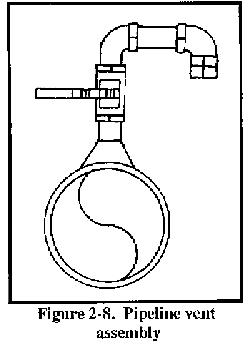
(6) Pipeline Vent Assembly. This assembly is made up of a 1-foot-long section of steel pipe that is grooved on both ends to receive the single-grooved coupling clamp (Figure 2-8). The assembly has a 3/4-inch vent tube with a 3/4-inch ball valve. A vent assembly is installed at high points to vent air from the system. It can also be installed as a low-point drain.
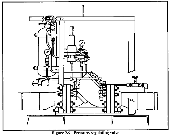
(7) Pressure-Regulating Valve (Figure 2-9). This valve--
- Is used to control pressure.
- Is used at the end of line (EOL) and at the TPT intake.
- Limits the pressure into the TPT switching manifold to below 125 psi.
- Maintains a line pressure of 50 psi or above in operation and 50 psi on shutdown.
- Will not open unless the upstream pressure is 50 psi or above.
- Is supplied as part of switching manifold.
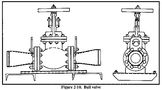
(8) Ball Valve. This valve (Figure 2-10) is used in switching manifolds to regulate the flow of fuel. The ball valve is not used in mainline pipe systems because scrapers cannot pass through them. Replace the packing in the valve when it is too compressed to lubricate the valve adequately and tightening the packing nut no longer stops a leak around the valve stern. Use graphite rings in the packing plan.
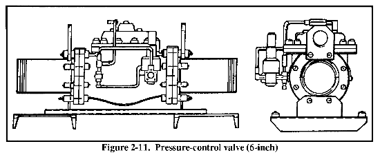
(9) Pressure-Control Valve (30 psi). This valve (Figure 2-11) is a back-pressure relief/regulator. The back-pressure controllers are installed in the recirculating hose lines from the fuel-dispensing assembly back to the tankage to maintain dispensing pressure of 30 psi (maximum). The valve is supplied as part of the fuel-dispensing assembly.
(10) Pressure-Control Valve (5 psi). This is a l/2-inch valve assembly (Figure 2-12). The valve is part of the two 1/2-inch dispensing points of the fuel-dispensing assembly, designated primarily for filling nonvented drums. The valve is supplied as part of the fuel-dispensing assembly.
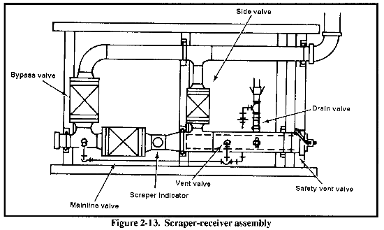
(11) Launcher and Receiver Assemblies. These assemblies are skid-mounted and are supplied with the IPDS for use in a scraper operation (Figure 2-13). Their function is essentially the same as the cleaner barrels. However, because these assemblies are preassembled with valves and scraper passage signals and are skid-mounted, they are more readily installed and simpler to operate and maintain. Currently, only a 6-inch design is available. Other sizes can be designed and manufactured. In an IPDS pipeline, a launcher assembly is installed immediately downstream of each pumping station. A receiver assembly is installed upstream of each pumping station and at the end of the line. This permits the controlled launching and receiving of scrapers (cleaners or pigs) in each pipeline segment for purging and cleaning the line as well as phase separation in certain operations.
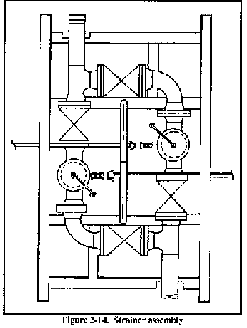
(12) Pipeline Strainer Assembly. This assembly consists of skid-mounted dual strainers and associated valves and piping (Figure 2-14). The assembly is supplied with the IPDS for installation in the pipeline pumping stations upstream of the pumps. The strainers collect dirt, sand, or other debris that may be in the system to protect the multistage pumps. The dual strainer installation allows for continuous protection even if one strainer is being cleaned or repaired. The 6-inch pipe ends on the unit can be coupled to the 6-inch IPDS piping system.
d. Pumps. Pipeline pumps consist of one or more impellers mounted on a rapidly rotating shaft. Liquid enters the impeller at the center and is impelled outward by centrifugal force into the volute of the pumping casing. The volute catches the discharge and converts peripheral velocity into head pressure while conducting the liquid at a reduced flow rate to the discharge nozzle of the pump casing. See the manufacturer's manual for operation and maintenance for each pump. Different pump units exist for an aluminum pipeline system and a steel pipeline system. Performance characteristic charts or curves for the pump units are in Appendix C.
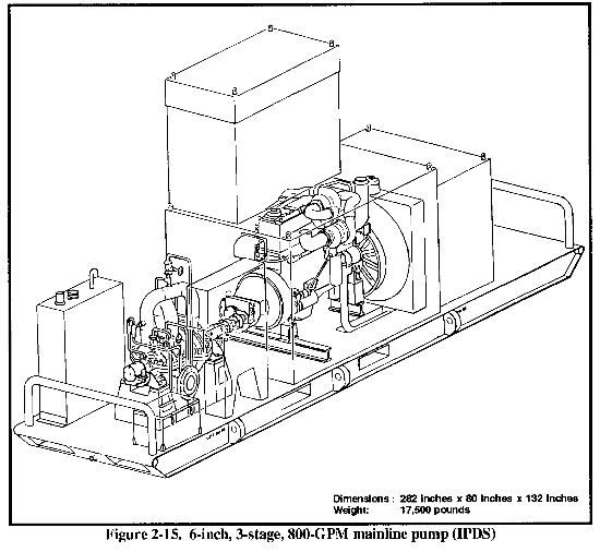
(1) 6-Inch, 3-Stage, 800-GPM Mainline Pump (IPDS) (Figure 2-15). This is a skid-mounted, diesel-engine-driven, centrifugal pump with an operational output of 800 GPM at 1,800 feet of head when pumping liquids with a specific gravity of 0.85. This rated capacity is delivered when any axis of the pumping assembly is positioned at any angle up to 5 degrees from the horizontal. The pumping assembly is suitable for operation at design capacity and head from -25° F to +135° F and at any altitude from sea level to 9,000 feet above sea level at an ambient condition of 100° F. It is used as a booster pump on the IPDS pipeline.
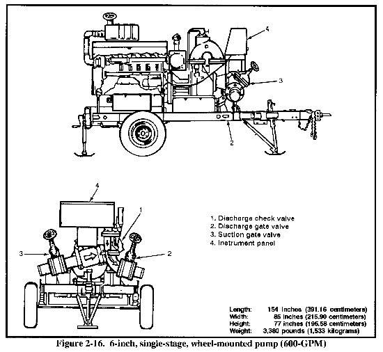
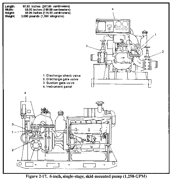
(2) 6-Inch, Single-Stage, Self-Priming Pump (600- and 1,250-GPM). This is a diesel-engine- driven, air-cooled, self-priming, centrifugal pump. Two models of this pump are available. The 600-GPM model (Figure 2-16), intended for hose-line use within terminals, is wheel-mounted and can operate in the automatic-discharge, pressure-control mode if the suction pressure is greater than 2 psi. The 1,250-GPM skid-mounted model (Figure 2-17) can only be operated in the manual mode. It is intended for flood, transfer, and general utility service. The rated capacity is delivered when the assembly is positioned at any angle up to 15 deprees from the horizontal. Prime is established within 2 minutes on a 10-foot suction lift after initially falling the pump casing. The pump unit has the capacity to pump petroleum products or potable water. Potable water should not be pumped after the pump has been contaminated by pumping petroleum products.
e. Miscellaneous Pipeline Equipment.
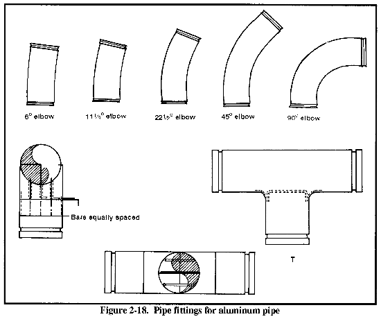
(l) Pipe Fittings. Standard, groove-type pipe fittings include elbows and Ts. Figure 2-18 shows some of these fittings.
NOTE:Due to a maximum allowable deflection between joints of aluminum pipe of 2 degrees, elbows must be used to change direction.
(2) Pipe-Repair Accessories.
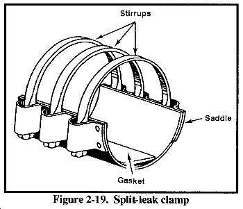
(a) Leak-repair clamps. These are specially designed clamps used to repair leaking pipes or couplings, temporarily. The split-leak clamp (Figure 2-19) consists of a saddle, a gasket, and stirrups that fit around the pipe where it leaks. An overcoupling-leak clamp (Figure 2-20) comes in two halves and covers a leaking coupling.
(b) Pup joints. Pup joints are 9 l/2-foot pipe sections with grooved ends and a constant wall thickness of 0.4 inch. These joints are used to make short pieces of pipe, or nipples, and can be cut and regrooved to close gaps less than 19 feet in newly constructed or broken pipelines and in pumping-station manifolding. Repair crews sometimes carry pup joints of assorted lengths. When a damaged section is removed (especially a surface-laid, grooved-coupled-type pipeline), the two ends are likely to spring apart. This occurs most often on long downhill slopes during very cold weather because of pipe contraction. The gap is likely to be 1 or 2 inches longer than the standard 19-foot length of grooved pipe section.
(3) Culvert Pipe. This is standard, nestable, steel corrugated pipe used for protecting pipelines located under roadways to minimize damage from the weight of passing vehicles. Culvert pipes come in 24-inch-long sections that are 12, 18, and 24 inches in diameter. The 12-and 18-inch pipes are 16 gauge; the 24-inch is 14 gauge.
2-4. Specialized Pipeline Tools and Equipment. Pioneer hand tools and standard table(s) of organization and equipment (TOE) earth-moving equipment are used to clear and level the right-of-way for pipelines and to prepare pumping station and tank-farm sites. The pipeline construction support company has limited earth-moving equipment but does have pioneer hand tools. Specialized equipment, assigned to the pipeline support company, is required for handling, placing, and installing valves, pumps, and pipeline anchors. This pipeline engineer company's primary mission is to support the engineer battalion in the construction and rehabilitation petroleum pipeline systems and facilities.
a. Tools.
(1) Hydraulic Drivehead Kit. The hydraulic drivehead is used to install pipeline anchors midway between the expansion devices along an aluminum pipeline system. A clamp is installed around the pipe and fastened to the anchor shaft, which is augured into the ground. The rotation rate is from 0 to 21 revolutions per minute (RPM). The anchors are also used in the construction of suspension bridges and pumping-station protective shelters. The hydraulic drivehead kit consists of a hydraulic motor and anchor adapter, which can be mounted on a JD410 or a SEE dipper stick after the bucket is removed. The drivehead takes about 30 minutes to install.
(2) Aluminum Pipe Section (Pup), 9 1/2 Feet. These are alloy, constant-wall pipe sections that come in frame bundles of 25 each (Figure 2-21). The pipe sections are used in the pumping stations, at the end of the pipeline, and at other points in the pipeline, as required for makeup. The sections can be cut to any required length and regrooved, using the supplied grooving and cutting equipment. The sections are standard with the 5-mile pipeline sets.
(3) Cutting, Grooving, and Beveling Machine (IPDS). This is a portable machine used to cut and groove nonstandard lengths of aluminum or steel pipe. This machine can also be used to bevel steel pipe for welding. The kit is made up of two large suitcases and two pipe stands. The machine is powered by a 250-cubic-foot-per-minute (cfm) air compressor or by a generator. It is used primarily for cutting and grooving pup joints required during mainline pumping-station construction. The pup joints are normally precut but can be cut on location. It takes about 30 minutes to cut and groove each end of pipe.
(4) Pipeline-Construction, Grooved-Coupling, Steel-Tubing Set. This set contains the tools and equipment needed to construct and maintain steel-coupled-type pipelines and pumping-station manifolds. The set consists of three chests that contain crowbars, shovels, brushes, files, rules, steel tapes, wrenches, lineup cages, and pipe-cleaning swabs needed to equip four pipeline-coupling crews and two pumping-station construction crews or six pipeline-coupling crews simultaneously.
(5) Supplemental Pipeline-Pumping-Station Set. This set supplements the general mechanic's tool set. It contains all of the tools required for operator maintenance and repair of the standard pumping units and the 4-, 6-, and 8-inch pumping-station manifolds. The set contains--
- Special pin removers and a special gooseneck-type screwdriver for removing pins in the coupling between pump engines and pumps.
- Locking pliers for removing pump seals.
- A thin adjustable wrench for backing up valve flange nuts between the flange and body of manifold valves.
- Box wrenches and open-end wrenches for removing and tightening pump-casing nuts and bolts.
- Pipe wrenches for maintenance of small-threaded pipes.
- Allen set-screw wrenches for removing and installing pump seals and coupling pins.
- Tappet wrenches for adjusting pumping engine valves.
- A socket-wrench handle and wrench sockets to fit all grooved-type coupling nuts in the 4-, 6-, and 8-inch pumping-station manifolds.
(6) Pipe-Fitter's General Tool Kit. This kit contains a variety of hand tools required for all types of pipe-fitting work on 1/8-to 2-inch pipe. The kit includes--
- A pipe cutter, die-head thread cutter, receding-segmental thread cutter, and hacksaw.
- A machinist's hammer, slip-point pliers, folding rule, screwdriver, and pipe vise.
- Various size pipe wrenches.
(7) Pipe-Fitter's Supplemental Tool Kit. This kit supplements the pipe-fitter's general tool kit. It contains a minimum of hand tools for cutting, threading, and fitting the 2 1/2- to 4-inch pipe.
(8) General Mechanic's Automotive Set. This set is an ordnance item of issue and is used primarily for minor maintenance or replacement of external accessories of pumping unit engines.
(9) Welded Steel Pipeline Construction Set.
(a) 4-, 6-, and 8-inch pipe sizes. This set contains the special size equipment, in the correct quantities, required for handling the 4-, 6-, and 8-inch pipe at stockpiles, stringing pipe sections, and laying and welding the pipeline.
(b) 12-inch size. This set contains the special size equipment, in the correct quantities, required for handling, stringing, laying, aligning, and beveling 12-inch pipe.
(10) Welder's Steel Supplemental Pipeline Construction Set. This set contains the tools and equipment required for welded pipeline construction that are not in the oxyacetylene torch outfit, cutting-and-welding equipment set. The set includes equipment for aligning flanges for welding, cleaning, making pipe bevels, marking pipe for mitered fittings, and removing welding slag. The set contains an initial supply of 1/8- and 5/32-inch, reverse-polarity, direct-current, mild steel electrode needed for pipeline welding. The set also includes an umbrella that is used to keep sunlight off buffed welds while being inspected, rain off hot welds, and sunlight from entering the back of the welder's helmet. This set is essential when using any welded-pipeline tool set described in Appendix B .
b. Equipment.
(1) 5-Ton, Cargo Long Bed. This truck is the primary vehicle used when constructing military pipelines. It is used to pull the 4-ton bolster trailer, to transport pipe to the construction site, and to haul valves, couplings, and soldiers to and from the construction site.
(2) 4-Ton Bolster Trailer. This is a dual-axle trailer with four bolster attachments and an adjustable tow boom (Figure 2-22). The bolster trailer is the primary means for transporting pipe from construction staging areas to the construction site. Pipe or tubing sections rest on each bolster assembly and are contained by the side stakes and binder chains or straps.
(3) 40-Ton Crane. This crane is used for lifting and placing mainline pumps at construction staging areas and at pumping-station locations.
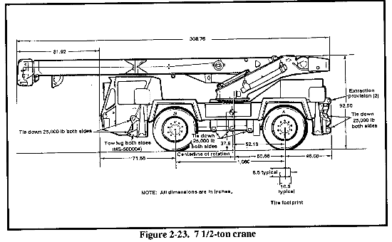
(4) 7 l/2-Ton Crane. This crane is used for lifting and placing the scraper-receiver assembly, strainer assembly, launcher assembly, and valves along the pipeline and at pumping station locations. (See Figure 2-23).
(5) SEE. This excavator is used to install pipeline anchors, dig and backfill culverts, and load and unload gate and check valves. (See Figure 1-4).
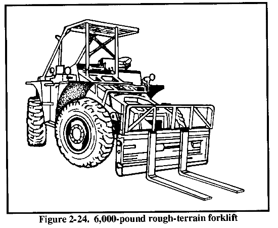
(6) 6,000-and 10,000-Pound Rough-Terrain Forklifts. These forklifts are used to load and unload pipeline components at construction staging areas along the pipeline trace. (See Figure 2-24).
|
NEWSLETTER
|
| Join the GlobalSecurity.org mailing list |
|
|
|


