

LESSON 2
| LESSON 2 | Major Engine Sections. |
| TEXT ASSIGNMENT | Reference Text AL0993, paragraphs 1.15-1.25. |
| LESSON OBJECTIVE | To teach you to distinguish between the five major sections of gas turbine engines. |
| CREDIT HOURS | 2 |
Section III. Major Engine Sections
1.15. GENERAL
Because of the many types of turbine engines, it is not possible to list all the major components and have the list apply to all engines. Several components are common to most turbine engines, and a knowledge of these will be helpful in developing a further understanding of aviation gas turbine engines. This section discusses the major engine sections individually.
1.16. ENGINE TERMINOLOGY
Engine terminology must be explained at this point to enable you to understand the terms used in discussing gas-turbine-engine operating theory explained in this course. Directional references are shown in figure 1.9. Table I shows engine symbols and abbreviations commonly used.
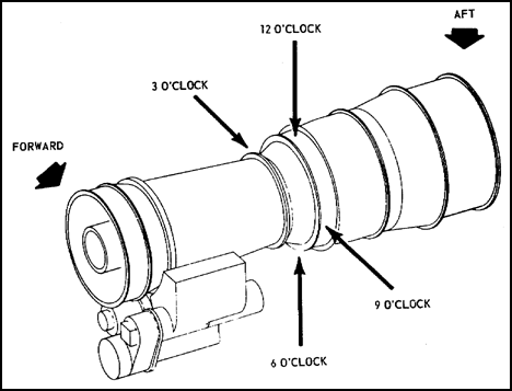
Figure 1.9. Directional References.

Table I. Commonly Used Gas Turbine Engine Symbols and Abbreviations
![]() a. Directional references. Front or forward -- cold end of engine. Rear or aft -- hot end of engine. Right and left -- determined by viewing the engine from the rear. Bottom -- determined by the location of the combustor drain valve. Top -- directly opposite, or 180 degrees from the combustor drain valve.
a. Directional references. Front or forward -- cold end of engine. Rear or aft -- hot end of engine. Right and left -- determined by viewing the engine from the rear. Bottom -- determined by the location of the combustor drain valve. Top -- directly opposite, or 180 degrees from the combustor drain valve.
These directional references hold true for most gas turbine engines. On some the power shaft is at the end where the exhaust gas is expelled. An engine of this design is the T73 installed on the CH-54 flying crane.
![]() b. Engine station notation. The engine is divided into stations to designate temperature (T) or pressure (P) measuring locations. Figure 1.10 shows a T53-L-13, labeling the engine stations. Any time a number is placed after the letter T or P, it denotes a specific location in the engine.
b. Engine station notation. The engine is divided into stations to designate temperature (T) or pressure (P) measuring locations. Figure 1.10 shows a T53-L-13, labeling the engine stations. Any time a number is placed after the letter T or P, it denotes a specific location in the engine.
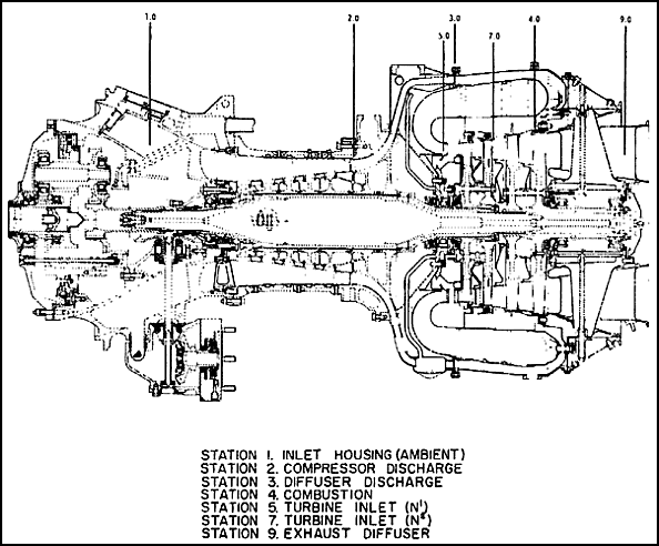
Figure 1.10. Engine Stations.
Example: The symbol T3, denotes the relative temperature at a specific location on the engine.
![]() c. Engine speed notation. The rotational speed of the engine is represented by the capital letter N. The first rotating mass, the gas producer has the symbol N1. Any time a number is placed after the letter N it denotes a specific system on the gas turbine engine.
c. Engine speed notation. The rotational speed of the engine is represented by the capital letter N. The first rotating mass, the gas producer has the symbol N1. Any time a number is placed after the letter N it denotes a specific system on the gas turbine engine.
1.17. ENGINE MODEL DESIGNATIONS
Letter designators are used to differentiate the jet-propulsion engines from reciprocating engines. A letter-number combination identifies each type of the various gas turbine engines. The J series designates true turbojet engines; the T designates turboprop or turboshaft engines; and the TF, turbofan engines.
One of these letters or letter combinations begins each engine model number, each part of which has a special significance. For example, in the engine model number T53-L13, the T means turboshaft; the 53 is simply the number assigned to this model by the Air Force when the engine was accepted or used experimentally. The Air Force/Army designation numbers are odd, while engines developed originally for the Navy get even numbers. The letter L is added by the manufacturer (in this case the Lycoming Division of AVCO) and the -13 is referred to as the "dash number." These are also always odd numbers, if the engine was developed for the Air Force/Army. The dash number designates the particular version of this model engine. When a production model is improved by major modifications, the dash number is changed.
In the past the Army has been getting their engines through the Air Force, using Air Force designators. However, now the Army has its own series of number designators. The first engine procured under the new system was the T700-GE-700 engine. The next engine developed for the Army will be the T701-manufacturer's code-three-digit dash number. The engines that were in the Army inventory previous to this new designator system will keep their present designators. However, when these models are improved, they will get the new three-digit number for a dash number. For example the improved version of the T53-L-15 is the T53-L-701.
1.18. AIR INLET SECTION
The amount of air required by a gas turbine engine is approximately ten times that of a reciprocating engine. The air inlet is generally a large, smooth aluminum or magnesium duct which must be designed to conduct the air into the compressor with minimum turbulence and restriction. The air inlet section may have a variety of names according to the desire of the manufacturer. It may be called the front frame and accessory section, the air inlet assembly, the front bearing support and shroud assembly, or any other term descriptive of its function. Usually, the outer shell of the front frame is joined to the center portion by braces that are often called struts. The anti-icing system directs compressor discharge air into these struts. The temperature of this air prevents the formation of ice that might prove damaging to the engine. Anti-icing systems are discussed further in the lesson covering the engines they may be installed on. Figure 1.11 illustrates the variety of inlet duct designs of Army aircraft.
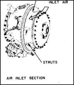 |
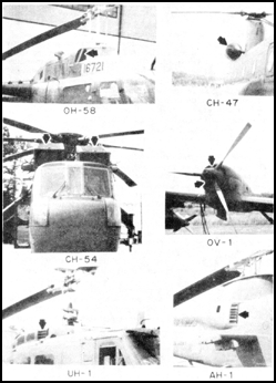 Figure 1.11. Inlet Duct Variations. |
1.19. COMPRESSOR SECTION
The compressor is the section of the engine that produces an increase in air pressure. It is made up of rotating and stationary vane assemblies. The first stage compressor rotor blades accelerate the air rearward into the first stage vane assemblies. The first stage vane assemblies slow the air down and direct it into the second stage compressor rotor blades. The second stage compressor rotor blades accelerate the air rearward into the second stage vane assemblies, and so on through the compressor rotor blades and vanes until air enters the diffuser section. The highest total air velocity is at the inlet of the diffuser. As the air passes rearward through the diffuser, the velocity of the air decreases and the static pressure increases. The highest static pressure is at the diffuser outlet.
The compressor rotor may be thought of as an air pump. The volume of air pumped by the compressor rotor is basically proportional to the rotor rpm. However, air density, the weight of a given volume of air, also varies this proportional relationship. The weight per unit volume of air is affected by temperature, compressor air inlet pressure, humidity, and ram air pressure*. If compressor air inlet temperature is increased, air density is reduced. If compressor air inlet pressure is increased, air density is increased. If humidity increases, air density is decreased. Humidity, by comparison with temperature, and pressure changes, has a very small effect on density. With increased forward speed, ram air pressure increases and air temperature and pressure increase.
*ram air pressure - free stream air pressure provided by the forward motion of the engine.
The following is an example of how air density affects compressor efficiency of the T62 gas turbine. At 100 percent N1 rpm, the compressor rotor pumps approximately 40.9 cubic feet of air per second. At standard day static sea level conditions, 59° F outside air temperature and 29.92" Hg barometric pressure, with 0 percent relative humidity and 0 ram air, air density is .07651 pound per cubic foot. Under these conditions, 40.9 cubic feet per second times .07651 pound per cubic feet equals approximately 3.13 pounds per second air flow through the engine. If the air density at the compressor inlet is less than on a standard day, the weight of air flow per second through the engine is less than 3.13 pounds per second. If N1 is less than 100 percent rpm on a standard day, the weight of air flow per second through the engine will be less than 3. 13 due to decreased volume flow at lower rpm. Because of this, N1 rpm varies with the power output. If output power is increased, N1 rpm will increase and vice versa. Thus, the weight of air pumped by the compressor rotor is determined by rpm and air density.
Compressor efficiency determines the power necessary to create the pressure rise of a given airflow, and it affects the temperature change which takes place in the combustion chamber. Therefore, the compressor is one of the most important components of the gas turbine engine because its efficient operation is the key to overall engine performance. The following subparagraphs discuss the three basic compressors used in gas turbine engines: the centrifugal-flow, the axial-flow, and axial-centrifugal-flow compressors. The axial-centrifugal-flow compressor is a combination of the other two and operates with characteristics of both.
![]() a. Centrifugal-flow compressor. Figure 1.12 shows the basic components of a centrifugal-flow compressor: rotor, stator, and compressor manifold.
a. Centrifugal-flow compressor. Figure 1.12 shows the basic components of a centrifugal-flow compressor: rotor, stator, and compressor manifold.

Figure 1.12. Typical Single-stage Centrifugal Compressor
As the impeller (rotor) revolves at high speed, air is drawn into the blades near the center. Centrifugal force accelerates this air and causes it to move outward from the axis of rotation toward the rim of the rotor where it is forced through the diffuser section at high velocity and high kinetic energy. The pressure rise is produced by reducing the velocity of the air in the diffuser, thereby converting velocity energy to pressure energy. The centrifugal compressor is capable of a relatively high compression ratio per stage. This compressor is not used on larger engines because of size and weight.
Because of the high tip speed problem in this design, the centrifugal compressor finds its greatest use on the smaller engines where simplicity, flexibility of operation, and ruggedness are the principal requirements rather than small frontal area and ability to handle high airflows and pressures with low loss of efficiency.
![]() b. Axial-flow compressor. The air is compressed, as the name implies, in a direction parallel to the axis of the engine. The compressor is made of a series of rotating airfoils called rotor blades, and a stationary set of airfoils called stator vanes. A stage consists of two rows of blades, one rotating and one stationary. The entire compressor is made up of a series of alternating rotor and stator vane stages as shown in figure 1.13.
b. Axial-flow compressor. The air is compressed, as the name implies, in a direction parallel to the axis of the engine. The compressor is made of a series of rotating airfoils called rotor blades, and a stationary set of airfoils called stator vanes. A stage consists of two rows of blades, one rotating and one stationary. The entire compressor is made up of a series of alternating rotor and stator vane stages as shown in figure 1.13.
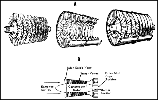
Figure 1.13. Axial-flow Compressor.
Axial flow compressors have the advantage of being capable of very high compression ratios with relatively high efficiencies; see figure 1.14. Because of the small frontal area created by this type of compressor, it is ideal for installation on high-speed aircraft. Unfortunately, the delicate blading and close tolerances, especially toward the rear of the compressor where the blades are smaller and more numerous per stage, make this compressor highly susceptible to foreign-object damage. Because of the close fits required for efficient air-pumping and higher compression ratios, this type of compressor is very complex and very expensive to manufacture. For these reasons the axial-flow design finds its greatest application where required efficiency and output override the considerations of cost, simplicity, and flexibility of operation. However, due to modern technology, the cost of the small axial-flow compressor, used in Army aircraft, is coming down.
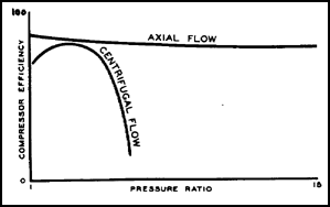
Figure 1.14. Compressor Efficiencies and Pressure Ratios.
![]() c. Axial-centrifugal-flow compressor. The axial-centrifugal-flow compressor, also called the dual compressor, is a combination of the two types, using the same operating characteristics. Figure 1.15 shows the compressor used in the T53 turbine engine. Most of the gas turbine engines used in Army aircraft are of the dual compressor design. Usually it consists of a five- or seven-stage axial-flow compressor and one centrifugal-flow compressor. The dual compressors are mounted on the same shaft and turn in the same direction and at the same speed. The centrifugal compressor is mounted aft of the axial compressor. The axial compressor contains numerous air-foil-shaped blades and vanes that accomplish the task of moving the air mass into the combustor at an elevated pressure.
c. Axial-centrifugal-flow compressor. The axial-centrifugal-flow compressor, also called the dual compressor, is a combination of the two types, using the same operating characteristics. Figure 1.15 shows the compressor used in the T53 turbine engine. Most of the gas turbine engines used in Army aircraft are of the dual compressor design. Usually it consists of a five- or seven-stage axial-flow compressor and one centrifugal-flow compressor. The dual compressors are mounted on the same shaft and turn in the same direction and at the same speed. The centrifugal compressor is mounted aft of the axial compressor. The axial compressor contains numerous air-foil-shaped blades and vanes that accomplish the task of moving the air mass into the combustor at an elevated pressure.
Figure 1.15. Axial-Centrifugal-Flow Compressor.
As the air is drawn into the engine, its direction of flow is changed by the inlet guide vanes. The angle of entry is established to ensure that the air flow onto the rotating compressor blades is within the stall-free (angle of attack) range. Air pressure or velocity is not changed as a result of this action. As the air passes from the trailing edge of the inlet guide vanes, its direction of flow is changed due to the rotational effect of the compressor. This change of airflow direction is similar to the action that takes place when a car is driven during a rain or snow storm. The rain or snow falling in a vertical direction strikes the windshield at an angle due to the horizontal velocity of the car.
In conjunction with the change of airflow direction, the velocity of the air is increased. Passing through the rotating compressor blades, the velocity is decreased, and a gain in pressure is obtained. When leaving the trailing edge of the compressor blades, the velocity of the air mass is again increased by the rotational effect of the compressor. The angle of entry on to the stationary stator vanes results from this rotational effect as it did on the airflow onto the compressor.
Passing through the stationary stator vanes the air velocity is again decreased resulting in an increase in pressure. The combined action of the rotor blades and stator vanes results in an increase in air -pressure; combined they constitute one stage of compression. This action continues through all stages of the axial compressor. To retain this pressure buildup, the airflow is delivered, stage by stage, into a continually narrowing airflow path. After passing from the last set of stator vanes the air mass passes through exit guide vanes. These vanes direct the air onto the centrifugal impeller.
The centrifugal impeller increases the velocity of the air mass as it moves it in a radial direction. The axial-centrifugal-flow compressor is discussed further in lesson 5.
![]() d. Compressor stall. Gas turbine engines are designed to avoid the pressure conditions that allow engine surge to develop, but the possibility of surge still exists in engines that are improperly adjusted or have been abused. Engine surge occurs any time the combustion chamber pressure exceeds that in the diffuser, and it is identified by a popping sound which is issued from the inlet. Because there is more than one cause for surge, the resultant sound can range from a single carburetor backfire pop to a machinegun sound.
d. Compressor stall. Gas turbine engines are designed to avoid the pressure conditions that allow engine surge to develop, but the possibility of surge still exists in engines that are improperly adjusted or have been abused. Engine surge occurs any time the combustion chamber pressure exceeds that in the diffuser, and it is identified by a popping sound which is issued from the inlet. Because there is more than one cause for surge, the resultant sound can range from a single carburetor backfire pop to a machinegun sound.
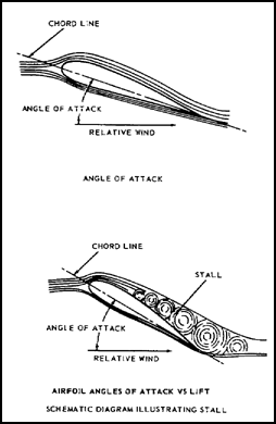
Engine surge is caused by a stall on the airfoil surfaces of the rotating blades or stationary vanes of the compressor. The stall can occur on individual blades or vanes or, simultaneously, on groups of them. To understand how this can induce engine surge, the causes and effects of stall on any airfoil must be examined.
All airfoils are designed to provide lift by producing a lower pressure on the convex (suction) side of the airfoil than on the concave (pressure) side. A characteristic of any airfoil is that lift increases with an increasing angle of attack, but only up to a critical angle. Beyond this critical angle of attack, lift falls off rapidly. This is due largely to the separation of the airflow from the suction surface of the airfoil, as shown in the sketch. This phenomenon is known as stall. All pilots are familiar with this condition and its consequences as it applies to the wing of an aircraft. The stall that takes place on the fixed or rotating blades of a compressor is the same as the stalling phenomenon of an aircraft wing.
1.20. COMPRESSOR CONSTRUCTION
Centrifugal - flow compressors are usually made of titanium. The diffuser is generally manufactured of a stainless steel alloy. A close fit is important between the compressor and its case to obtain maximum compressor efficiency. Correct rotor assembly balancing is essential for safe operation because of the high rpm. Balancing the rotor can be accomplished by removing metal from specified areas of the compressor or by using balancing weights installed in holes in the hub of the compressor. On some engines where the compressor and turbine wheel are balanced as a unit, special bolts and nuts having slight variations in weight are used.
Axial-flow compressors are constructed of many different materials, depending upon the load and temperature under which the unit must operate. The rotor blades are generally cast of stainless-steel alloy. Some manufacturers use mdybdenum coated titanium blades to dampen vibrations on some stages of rotor blades. The clearance between the rotor blades and the outer case is most important. Some companies coat the inner surface of the compressor case with a soft material that can be worn away by the blades as they expand because of the heat generated from compressing the air. This type of compressor uses the "wear-fit" method to form its own clearance between the compressor case and the rotor blade tip.
Methods of attaching the blade to the disk or hub vary between manufacturers, with the majority using some variation of the dove-tail method to hold the rotor blades to the disk. Various other methods are used to anchor the blades in place. Some blades do not have a tight fit in the disk, but rather are seated by centrifugal force during engine operation. By allowing the blades to move, vibrational stress is reduced during start and shutdown. Stator vanes, shown in figure 1.16, can be either solid or hollow construction, and are connected together at their tips by a shroud. This shrouding serves two purposes. First, it provides support, and second, it provides the necessary air seal between rotating and stationary parts. Most manufacturers use the split compressor cases, while some others favor a weldment, forming a continuous case. The advantages of the split case lie in the fact that the compressor and stator blades are readily available to inspection. The one-piece case offers simplicity and strength because it is one piece; in most instances, it is a principal structural part of the engine and is usually made of cast aluminum, magnesium, or steel. Figures 1.16 and 1.17 show shrouded compressor stators in both the split case and the one-piece case.
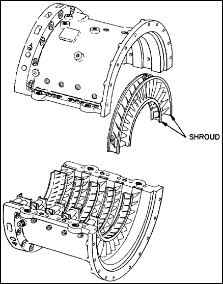
Figure 1.16. Shrouded Compressor Stators.
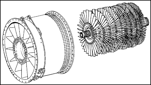
Figure 1.17. One-Piece Compressor Case.
1.21. COMBUSTION SECTION
Today, three basic combustion chambers are in use. They are the annular combustion chamber, the can type, and the combination of the two called the can-annular. Variations of these basic systems are used in a number of engines. The three systems are discussed individually in the following subparagraphs. The most commonly used gas turbine engine in Army aircraft is the annular reverse-Row type. The combustion section contains the combustion chambers, igniter plugs, and fuel nozzles or vaporizing tubes. It is designed to burn a fuel-air mixture and deliver the combusted gases to the turbine at a temperature which will not exceed the allowable limit at the turbine inlet.
Fuel is introduced at the front end of the burner in a highly atomized spray from the fuel nozzles. Combustion air flows in around the fuel nozzle and mixes with the fuel to form a correct fuel-air mixture. This is called primary air and represents approximately 25 percent of total air taken into the engine. The fuel-air mixture which is to be burned is a ratio of 15 parts of air to 1 part of fuel by weight. The remaining 75 percent of the air is used to form an air blanket around the burning gases and to lower the temperature. This temperature may reach as high as 3500° F. By using 75 percent of the air for cooling, the temperature operating range can be brought down to about half, so the turbine section will not be destroyed by excessive heat. The air used for burning is called primary air- and that for cooling is secondary air. The secondary air is controlled and directed by holes and louvers in the combustion chamber liner.
Igniter plugs function only during starting, being cut out of the circuit as soon as combustion is self-supporting. On engine shutdown, or, if the engine fails to start, the combustion chamber drain valve, a pressure-actuated valve, automatically drains any remaining unburned fuel from the combustion chamber. All combustion chambers contain the same basic elements: a casing or outer shell, a perforated inner liner or flame tube, fuel nozzles, and some means of initial ignition. The combustion chamber must be of light construction and is designed to burn fuel completely in a high velocity airstream. The combustion chamber liner is an extremely critical engine part because of the high temperatures of the flame. The liner is usually constructed of welded high-nickel steel. The most severe operating periods in combustion chambers are encountered in the engine idling and maximum rpm ranges. Sustained operation under these conditions must be avoided to prevent combustion chamber liner failure.
![]() a. The annular-type combustion chamber shown in figure 1.18 is used in engines of the axial-centrifugal-flow compressor design. The annular combustion chamber permits building an engine of a small and compact design. Instead of individual combustion chambers, the primary compressed air is introduced into an annular space formed by a chamber liner around the turbine assembly. A space is left between the outer liner wall and the combustion chamber housing to permit the flow of secondary cooling air from the compressor. Primary air is mixed with the fuel for combustion. Secondary (cooling) air reduces the temperature of the hot gases entering the turbine to the proper level by forming a blanket of cool air around these hot gases.
a. The annular-type combustion chamber shown in figure 1.18 is used in engines of the axial-centrifugal-flow compressor design. The annular combustion chamber permits building an engine of a small and compact design. Instead of individual combustion chambers, the primary compressed air is introduced into an annular space formed by a chamber liner around the turbine assembly. A space is left between the outer liner wall and the combustion chamber housing to permit the flow of secondary cooling air from the compressor. Primary air is mixed with the fuel for combustion. Secondary (cooling) air reduces the temperature of the hot gases entering the turbine to the proper level by forming a blanket of cool air around these hot gases.
1. ANNULAR TYPE COMBUSTION CHAMBER LINER
2. COMBUSTION CHAMBER HOUSING ASSEMBLY
Figure 1.18. Annular-type Combustion Chamber.
The annular combustion chamber offers the advantages of a larger combustion volume per unit of exposed area and material weight, a smaller exposed area resulting in lower pressure losses through the unit, and less weight and complete pressure equalization.
![]() b. The can-type combustion chamber is one made up of individual combustion chambers. This type of combustion chamber is so arranged that air from the compressor enters each individual chamber through the adapter. Each individual chamber is composed of two cylindrical tubes, the combustion chamber liner and the outer combustion chamber, shown in figure 1.19. Combustion takes place within the liner. Airflow into the combustion area is controlled by small louvers located in the inner dome, and by round holes and elongated louvers along the length of the liner. Airflow into the combustion area is controlled by small louvers located in the inner dome, and by round holes elongated louvers along the length of the liner.
b. The can-type combustion chamber is one made up of individual combustion chambers. This type of combustion chamber is so arranged that air from the compressor enters each individual chamber through the adapter. Each individual chamber is composed of two cylindrical tubes, the combustion chamber liner and the outer combustion chamber, shown in figure 1.19. Combustion takes place within the liner. Airflow into the combustion area is controlled by small louvers located in the inner dome, and by round holes and elongated louvers along the length of the liner. Airflow into the combustion area is controlled by small louvers located in the inner dome, and by round holes elongated louvers along the length of the liner.
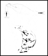
Figure 1.19. Can-type Combustion Chamber (Cutaway).
Through these openings flows the air that is used in combustion and cooling. This air also prevents carbon deposits from forming on the inside of the liner. This is important, because carbon deposits can block critical air passages and disrupt airflow along the liner walls causing high metal temperatures and short burner life.
Ignition is accomplished during the starting cycle. The igniter plug is located in the combustion liner adjacent to the start fuel nozzle. The Army can-type engine employs a single can-type combustor.
![]() c. Can-annular combustion chamber. This combustion chamber uses characteristics of both annular and can-type combustion chambers. The can-annular combustion chamber consists of an outer shell, with a number of individual cylindrical liners mounted about the engine axis as shown in figure 1.20. The combustion chambers are completely surrounded by the airflow that enters the liners through various holes and louvers. This air is mixed with fuel which has been sprayed under pressure from the fuel nozzles. The fuel-air mixture is ignited by igniter plugs, and the flame is then carried through the crossover tubes to the remaining liners. The inner casing assembly is both a support and a heat shield; also, oil lines run through it.
c. Can-annular combustion chamber. This combustion chamber uses characteristics of both annular and can-type combustion chambers. The can-annular combustion chamber consists of an outer shell, with a number of individual cylindrical liners mounted about the engine axis as shown in figure 1.20. The combustion chambers are completely surrounded by the airflow that enters the liners through various holes and louvers. This air is mixed with fuel which has been sprayed under pressure from the fuel nozzles. The fuel-air mixture is ignited by igniter plugs, and the flame is then carried through the crossover tubes to the remaining liners. The inner casing assembly is both a support and a heat shield; also, oil lines run through it.
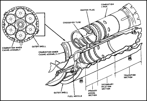
Figure 1.20. Can-Annular Combustion Chamber.
1.22. TURBINE SECTION
A portion of the kinetic energy of the expanding gases is extracted by the turbine section, and this energy is transformed into shaft horsepower which is used to drive the compressor and accessories. In turboprop and turboshaft engines, additional turbine rotors are designed to extract all of the energy possible from the remaining gases to drive a powershaft.
![]() a. Types of turbines. Gas turbine manufacturers have concentrated on the axial-flow turbine shown in figure 1.21. This turbine is used in all gas-turbine-powered aircraft in the Army today. However, some manufacturers are building engines with a radial inflow turbine, illustrated in figure 1.22. The radial inflow turbine has the advantage of ruggedness and simplicity, and it is relatively inexpensive and easy to manufacture when compared to the axial-flow turbine. The radial flow turbine is similar in design and construction to the centrifugal-flow compressor described in paragraph 1.19a. Radial turbine wheels used for small engines are well suited for a higher range of specific speeds and work at relatively high efficiency.
a. Types of turbines. Gas turbine manufacturers have concentrated on the axial-flow turbine shown in figure 1.21. This turbine is used in all gas-turbine-powered aircraft in the Army today. However, some manufacturers are building engines with a radial inflow turbine, illustrated in figure 1.22. The radial inflow turbine has the advantage of ruggedness and simplicity, and it is relatively inexpensive and easy to manufacture when compared to the axial-flow turbine. The radial flow turbine is similar in design and construction to the centrifugal-flow compressor described in paragraph 1.19a. Radial turbine wheels used for small engines are well suited for a higher range of specific speeds and work at relatively high efficiency.
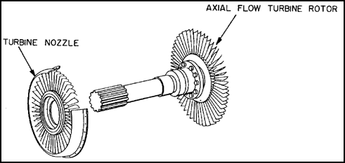
Figure 1.21. Axial-flow Turbine Rotor.
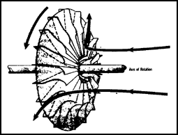
Figure 1.22. Radial Inflow Turbine.
The axial-flow turbine consists of two main elements, a set of stationary vanes followed by a turbine rotor. Axial-flow turbines may be of the single-rotor or multiple-rotor type. A stage consists of two main components: a turbine nozzle and a turbine rotor or wheel, as shown in figure 1.21. Turbine blades are of two basic types, the impulse and the reaction. Modern aircraft gas turbines use blades that have both impulse and reaction sections, as shown in figure 1.23.
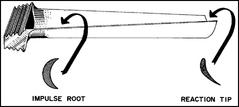
Figure 1.23. Impulse-Reaction Turbine Blade.
The stationary part of the turbine assembly consists of a row of contoured vanes set at a predetermined angle to form a series of small nozzles which direct the gases onto the blades of the turbine rotor. For this reason, the stationary vane assembly is usually called the turbine nozzle, and the vanes are called nozzle guide vanes.
![]() b. Single-rotor turbine. Some gas turbine engines use a single-rotor turbine, with the power developed by one rotor. This arrangement is used on engines where low weight and compactness are necessary. A single-rotor, single-stage turbine engine is shown in figure 1.24, and a multiple-rotor, multiple-stage turbine engine is shown in figure 1.25.
b. Single-rotor turbine. Some gas turbine engines use a single-rotor turbine, with the power developed by one rotor. This arrangement is used on engines where low weight and compactness are necessary. A single-rotor, single-stage turbine engine is shown in figure 1.24, and a multiple-rotor, multiple-stage turbine engine is shown in figure 1.25.
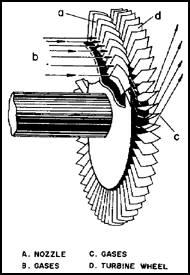
Figure 1.24. Single-rotor,Single-stage Turbine.
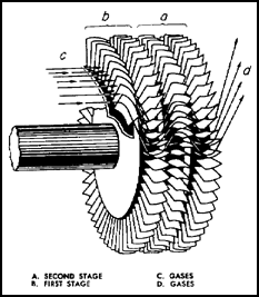
Figure 1.25. Multiple-rotor,Multiple-stage Turbine.
![]() c. Multiple-rotor turbine. In the multiple-rotor turbine the power is developed by two or more rotors. As a general rule, multiple-rotor turbines increase the total power generated in a unit of small diameter. Generally the turbines used in Army aircraft engines have multiple rotors. Figure 1.26 illustrates a multistage, multiple-rotor turbine assembly.
c. Multiple-rotor turbine. In the multiple-rotor turbine the power is developed by two or more rotors. As a general rule, multiple-rotor turbines increase the total power generated in a unit of small diameter. Generally the turbines used in Army aircraft engines have multiple rotors. Figure 1.26 illustrates a multistage, multiple-rotor turbine assembly.
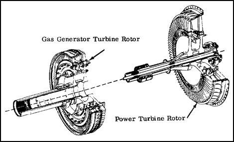
Figure 1.26. Multirotor - Multistage Turbine.
1.23. TURBINE CONSTRUCTION
The turbine rotor is one of the most highly stressed parts in the engine. It operates at a temperature of approximately 1,700° F. Because of the high rotational speeds, over 40,000 rpm for the smaller engines, the turbine rotor is under severe centrifugal loads. Consequently, the turbine disk is made of specially alloyed steel, usually containing large percentages of chromium, nickel, and cobalt. The turbine rotor assembly is made of two main parts, the disk and blades.
Nozzle vanes may be either cast or forged. Some vanes are made hollow to allow cooling air to flow through them. All nozzle assemblies are made of very high-strength steel that withstands the direct impact of the hot gases flowing from the combustion chamber.
The turbine blades are attached to the disk by using the "fir tree" design, shown in figure 1.27, to allow for expansion between the disk and the blade while holding the blade firmly to the disk against centrifugal loads. The blade is kept from moving axially either by rivets or special locking devices. Turbine rotors are of the open-tip type as shown in figure 1.27, or the shroud type as shown in figure 1.28.
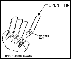
Figure 1.27. Turbine Wheel Open Tip.
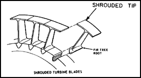
Figure 1.28. Turbine Blade "Fir Tree Root" Shroud.
The shroud acts to prevent gas losses over the blade tip and excessive blade vibrations. Distortion under severe loads tends to twist the blade toward low pitch, and the shroud helps to reduce this tendency. The shrouded blade has an aerodynamic advantage in that thinner blades can be used with the support of the shroud. Shrouding, however, requires that the turbine run cooler or at reduced rpm because of the extra mass at the tip.
Blades are forged or cast from alloy steel and machined and carefully inspected before being certified for use. Manufacturers stamp a "moment weight" number on the blade to retain rotor balance when replacement is necessary. Turbine blade maintenance and replacement are covered in lesson 4.
The hot gases are exhausted overboard through the exhaust diffuser section. Internally, this section supports the power turbine and aft portion of the powershaft. The exhaust diffuser is composed of an inner and outer housing, separated by hollow struts across the exhaust passage. The inner housing is capped by either a tailcone or a cover plate which provides a chamber for cooling the powershaft bearing. A typical exhaust diffuser section is shown in figure 1.29.
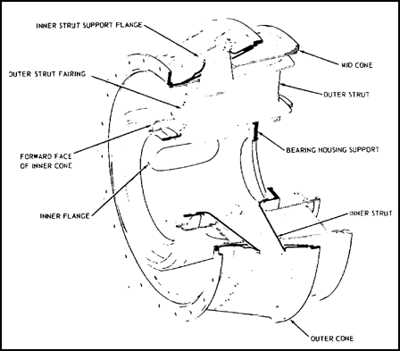
Figure 1.29. Exhaust Diffuser Section.
Turboshaft engines used in helicopters do not develop thrust by use of the exhaust duct. If thrust were developed by the engine exhaust gas, it would be impossible to maintain a stationary hover; therefore, helicopters use divergent ducts. These ducts reduce gas velocity and dissipate any thrust remaining in the exhaust gases. On fixed wing aircraft, the exhaust duct may be the convergent type, which accelerates the remaining gases to produce thrust which adds additional shaft horsepower to the engine rating. The combined thrust and shaft horsepower is called equivalent shaft horsepower (ESHP).
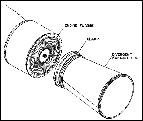
Figure 1.30. Divergent Exhaust Duct.
1.25. SUMMARY
The gas turbine engine has five major sections: inlet, compressor, combustion, turbine, and exhaust. Engine terminology includes directional references, engine stations, and model designations.
Gas turbine engine construction is not limited to one type of compressor. The compressor may be either centrifugal or axial or a combination of the two. Compressors are made in single or multiple stage assemblies.
Three basic types of combustion chambers are in use: the annular, can, or a combination of the two called can-annular or cannular.
Gas turbine engines may use either an axial-flow turbine or a radial-inflow turbine. The turbine section may have a single- or multiple-stage turbine. The hot exhaust gases are exhausted overboard through the exhaust section. Exhaust ducts used on helicopters are divergent. The ducts used on fixed-wing aircraft may be of the convergent type.
GO TO: