LESSON 5
| LESSON 5 | Lycoming T53. |
| TEXT ASSIGNMENT | Reference Text AL0993, paragraphs 4.1-4.23. |
| LESSON OBJECTIVE | To enable you to describe the operation of the T53 engine and its sections, its models and specifications, and its major engine systems and assemblies. |
| CREDIT HOURS | 2 |
Chapter 4
LYCOMING T53
4.1. INTRODUCTION
The two sections of this chapter discuss, in detail, the Lycoming T53 series gas turbine engine used in Army aircraft. Section I gives a general description of the T53, describes the engine's five sections, explains engine operation, compares models and specifications, and describes the engine's airflow path. The second section covers major engine assemblies and systems.
Basically, all models of the T53 engine are of the same design. The major difference on models later than the T53-L-11 is that they have two gas producer turbines (N1) and two free-power turbines (N2) instead of the single stage turbine used on the L- 11 and earlier models. The engine models described in this chapter are primarily the T53-L-13, and T53-L-701. However, the description and information given is applicable to all models except where noted.
Section I. Operational Description of the T53 Gas Turbine Engine
4.2. GENERAL
The information in this section is important to you because it describes the engine's airflow path through the inlet, compressor, diffuser, combustion, and exhaust sections, and explains the operational relationship of these sections. In addition differences between models and specifications are compared. Except for the paragraph comparing models, this section's coverage is limited to the T53-L-13 and -701.
4.3. GENERAL DESCRIPTION
The T53 series gas turbine engine is an annular reverse-flow, free-power turbine powerplant developed for fixed- and rotary-wing aircraft. As shown in figure 4.1, the engine consists of inlet, compressor, diffuser, combustion, and exhaust sections. All these are designed to include an annular or circular flow path for the air or hot gases, and they are structurally dependent on one another. These sections support all internal rotating systems and have attaching capabilities for engine accessories.

Figure 4.1. T53 Engine (Exploded View)
4.4. OPERATIONAL DESCRIPTION
The discussion in this paragraph describes briefly the airflow through the engines and the operation of the Lycoming T53. The capital letters in parentheses such as (A), (B), (C) and so on in the discussion correspond to similar letters in figure 4.2 and refer you to that particular portion of the engine diagram.
![]() a. Air flow. Atmospheric air (A) is drawn into the annular air passageway of the inlet housing (B) and passes rearward across the variable inlet guide vanes (C). The vanes direct the air into the engine compressor section. The air passageway in the compressor section contains Eve rotating axial compressor stages with five sets of stationary stator vanes, a set of exit guide vanes (D), and one centrifugal compressor (E). As the air passes through this section, each rotating axial compressor stage increases the pressure. The exit guide vanes guide the air onto the centrifugal compressor which further accelerates the air as it passes radially into the diffuser housing air passageway (F). Vanes in the diffuser air passageway convert the high velocity of the air into pressure and also change the radial airflow to a rearward flowing direction.
a. Air flow. Atmospheric air (A) is drawn into the annular air passageway of the inlet housing (B) and passes rearward across the variable inlet guide vanes (C). The vanes direct the air into the engine compressor section. The air passageway in the compressor section contains Eve rotating axial compressor stages with five sets of stationary stator vanes, a set of exit guide vanes (D), and one centrifugal compressor (E). As the air passes through this section, each rotating axial compressor stage increases the pressure. The exit guide vanes guide the air onto the centrifugal compressor which further accelerates the air as it passes radially into the diffuser housing air passageway (F). Vanes in the diffuser air passageway convert the high velocity of the air into pressure and also change the radial airflow to a rearward flowing direction.
At this point the air enters the combustor section, passing around and into the annular combustion area (G) through slots, louvers, holes, and scoops fabricated in the combustion liner. On entering the combustion area, flow direction is reversed while both air velocity and pressure drop. The air, at the same time, performs the multiple functions of cooling the combustor liner; mixing with fuel, and burning, sustaining, and maintaining the high heat combustion within a confined area; and absorbing the heat of combustion so as to lower the heat to a usable temperature. Combustion is made possible by introducing fuel into the combustion area through 22 atomizers. The atomized fuel mixes with the air, burns, and produces temperatures as high as 3,500 degrees F.
As previously stated, this exceedingly hot gas is cooled as it flows forward in the combustion area to the deflector, which reverses the hot gas flow. Now flowing rearward, the gas is directed across the two-stage gas producer nozzle turbine system. The first stage nozzle (H) directs the high energy gas onto the first stage turbine (I), across the second stage nozzle (J) onto the second stage turbine (K). The power system also uses the two-stage nozzle turbine concept. Therefore, on leaving the second stage gas producer turbine, the gas, still possessing a high work potential, flows across the third stage nozzle (L) onto the third stage turbine (M), across the fourth stage nozzle (N) onto the fourth stage turbine (O). On passing from the fourth stage turbine, the gas is exhausted into the atmosphere through the exhaust diffuser passageway (P).
![]() b. Operation. The engine is started by energizing the starter, the starting fuel solenoid valve, and the ignition system. Starting fuel flows into the combustion chamber through four starting fuel nozzles and is ignited by the four igniter plugs adjacent to the starting fuel nozzles at the 2, 4, 8, and 10 o'clock positions. At 8 to 13 percent N1 speed, the fuel regulator valve opens, and main fuel flows into the combustion chamber through 22 fuel atomizers and is ignited by the burning starting fuel. As compressor rotor speed (N1) increases, the additional fuel mixes with compressed air and burns.
b. Operation. The engine is started by energizing the starter, the starting fuel solenoid valve, and the ignition system. Starting fuel flows into the combustion chamber through four starting fuel nozzles and is ignited by the four igniter plugs adjacent to the starting fuel nozzles at the 2, 4, 8, and 10 o'clock positions. At 8 to 13 percent N1 speed, the fuel regulator valve opens, and main fuel flows into the combustion chamber through 22 fuel atomizers and is ignited by the burning starting fuel. As compressor rotor speed (N1) increases, the additional fuel mixes with compressed air and burns.
When compressor speed increases to 40 percent N1 speed, the starter, starting fuel solenoid valve, and ignition system should be de-energized. Combustion gases pass through the gas producer nozzle assemblies; impinge upon (strike) the blades of the gas producer rotor assemblies; How through the power turbine nozzle assemblies; and impinge upon the blades of the power turbine rotor assemblies. Approximately 60 percent of the gas energy passing from the combustion chamber is extracted by the N1 turbine rotors to drive the compressor, while the remaining energy is extracted by the N2 power turbines to drive the power shaft. The power turbine rotor assemblies are splined to the power shaft and secured by the power-shaft bolt. The power shaft is splined into the sun-gear shaft, which drives the output reduction gearing and, in turn, the power output gear shaft.
4.5. MODEL COMPARISON
The Lycoming T53 engine design was submitted to the military, and in 1952 a contract was awarded to the Army for development of the present T53 gas turbine engine. The basic T53 powerplant is a free turbine consisting of two mechanically independent stages -- a compressor and a power turbine. From the initial prototype version, many models of the T53 have been developed. The following models are currently being used by the Army.
T53-L-13 -- a second-generation shaft turbine engine having all the improvements developed for the T53- L-11/11A/11B versions. It introduces combustion chamber atomizers (replacing the vaporizer tubes), two gas producer and power turbine rotors instead of one of each, and four atomizing type starting fuel nozzles and four igniter plugs.
T53-L-13A -- Engine model T53- L-13 containing additional modifications is designated as model T53-L-13A. This model incorporates the following improvements: a 34-blade second stage compressor disc assembly; No. 2 bearing forward and aft seals, bearing housing and retaining plate; oil-lubricated fuel-control drive splines, an air diffuser and accessory gearbox with improved oil scavenge capability; and a 6-probe exhaust gas temperature harness assembly.
T53-L-15 -- a turboprop equivalent of the T53-L-13, the T53-L-15 has been flat-rated and is equipped with a torque limiter to prevent engine torque from exceeding the limitations imposed by the airframe manufacturer. Other differences include a 6-probe, 12-point exhaust-gas thermocouple harness, a fuel heater, fuel filter, and bypass fuel filter. Also, the manual operating feature of the fuel control has been deleted.
T53-L-701 -- the newest turboprop addition to the Lycoming T53 series engines is designated the T53-L-701. The most dynamic feature of the T53-L-701 is a newly developed Lycoming split-power reduction gear assembly, using an electric torquemetering system. This split-power reduction gear assembly permits development of the full mechanical and thermodynamic capabilities of the T53-L-701 by allowing operation to 1,451 shp. Very accurate torque measurements on the T53-L-701 are provided by an electric torquemeter system.
4.6. SPECIFICATION SUMMARY
Specifications for the T53-L-13 and 701 engines used in Army aircraft are summarized in the following chart.
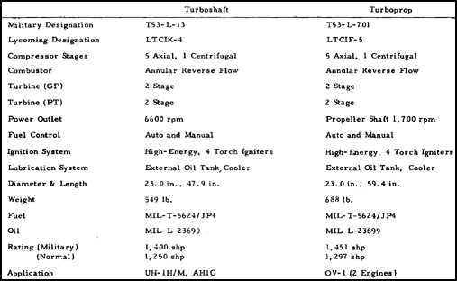
4.7. DIRECTIONAL REFERENCES AND ENGINE STATIONS
The diagrams in figures 4.3 and 4.4 show directional references and engine stations. Notice that power output is taken from the front end and that exhaust gas is expelled from the rear end. Right and left sides for the engine are determined by viewing the engine from the rear. The engine's bottom is determined by the accessory drive gearbox's location. The top of the engine is directly opposite, or 180 degrees from the accessory drive gearbox. Rotational direction is determined by viewing from the rear of the engine. The compressor rotor and gas producer turbines rotate in a counterclockwise direction. The power turbines and output gearshaft rotate in a clockwise direction.

Figure 4.3. Engine Orientation Diagram (T53-L-13).

Figure 4.4. Engine Stations (T53-L-13).
The T53 engine has 14 ports for test measuring, and it is divided into stations to designate temperature (T) and pressure (P) measuring locations. Engine stations for the T53-L-13 are shown in Figure 4.4. They are identified on the drawing as 1.0, 2.0, on up to 9.0, but in practice they are spoken of as 1, 2, 3, and so forth. Station 1, on the inlet housing, is for ambient air. Stations 2 and 3 are for compressor and diffuser discharge air. Station 4 is located at the combustor section. Stations 5 and 7 designate turbine inlets N1 and N2. Station 9 is the location for the exhaust diffuser. No stations are shown for 6 and 8, because these numbers are not used.
4.8. SUMMARY
Following the air path through the engine shows how air is drawn into and moved through the engine's Eve sections. Air brought into the compressor section is accelerated into the diffuser-housing air passageway. As the air moves through the passageway, its velocity changes to pressure and, under pressure, the air enters the combustion chamber to mix with injected fuel. The flow of the hot gases across the turbine rotors produces mechanical energy to drive the compressor and propel the aircraft.
The various models of the T53 include the L-13, L-13A, L-15, and L-701. Some of the specifications differ in each model.
Section II. Major Engine Systems and Assembles
4.9. GENERAL
Starting at the front of the engine and working rearward we discuss the major engine assemblies. Systems such as fuel, oil, and electrical are covered in their entirety, after the major engine assemblies. Also keep in mind that the T53-L-13 is a turboshaft engine, and the T53-L-701 is a turboprop engine. The turboprop engine has a propeller reduction gear assembly in the inlet housing where the turboshaft engine has a smaller output reduction gear assembly.
4.10. INLET HOUSING ASSEMBLY
The forward structural support of the engine is provided by the inlet housing assembly shown in figure 4.5. The outer housing, supported by six hollow struts, forms the outer wall of the annular air inlet and houses the anti-icing manifold. The inner housing forms the inner wall of the inlet area.
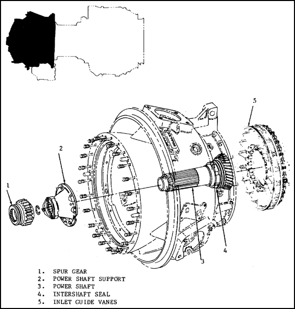
Figure 4.5. Inlet Housing.
Enclosed in the inlet housing is the output reduction carrier and gear assembly, the oil transfer support assembly, and the accessory drive carrier. A torquemeter valve and cylinder, power shaft support bearing, and No. 1 main bearing are also mounted internally. At the rear of the housing the inlet guide vanes are installed in the airflow path to direct air at the proper angle onto the first stage of the compressor rotor.
Externally the inlet housing provides mounting points for the overspeed governor and tachometer drive assembly, and the N1 and N2 accessory drive gearbox assemblies. The housing also has engine mounting pads, a hoisting eye, and engine and airframe accessory mounting pads. The entire one-piece, cast-magnesium housing is coated with a heat-applied epoxy paint (HAE) to prevent erosion and corrosion.
The gas producer compressor assembly is supported at its forward end by the No. 1 main bearing, figure 4.6, which is a ball bearing to absorb thrust and radial loads, mounted within a leaf spring retainer that dampens minor torsional vibrations. The aft side of the bearing is sealed by a positive contact carbon seal aided by springs and pressurized air. A radial labyrinth seal is located forward of the carbon seal, operating on pressurized air through bleed holes; it assists in positive sealing of the bearing area. The forward end of the power shaft is supported by an unnumbered roller bearing within the inlet housing. All main bearings may be seen by referring back to figure 4.4.
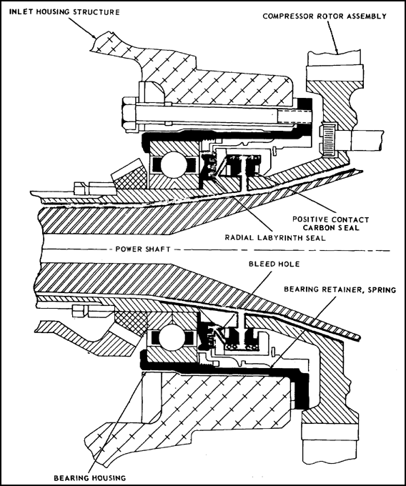
Figure 4.6. No. 1 Bearing and Seal Area.
The following subparagraphs give some information about the T53-L-13 output reduction carrier and gear assembly and the T53-L-701 propeller reduction carrier and gear assembly.
![]() a. Output reduction carrier and gear assembly on the turboshaft engine in the T53-L-13 is located in the inner inlet housing as shown in figure 4.7. It consists of the support housing (1), carrier assembly (2), three planetary gear assemblies (3), oil transfer tubes (4), an output gear shaft (5), and a torquemeter assembly (not shown). The sun gearshaft is splined and bolted to the forward end of the power shaft and drives the three planetary gears, which in turn drive the output gearshaft. Reduction ratio of the turboshaft engine is 3.2 to 1.
a. Output reduction carrier and gear assembly on the turboshaft engine in the T53-L-13 is located in the inner inlet housing as shown in figure 4.7. It consists of the support housing (1), carrier assembly (2), three planetary gear assemblies (3), oil transfer tubes (4), an output gear shaft (5), and a torquemeter assembly (not shown). The sun gearshaft is splined and bolted to the forward end of the power shaft and drives the three planetary gears, which in turn drive the output gearshaft. Reduction ratio of the turboshaft engine is 3.2 to 1.
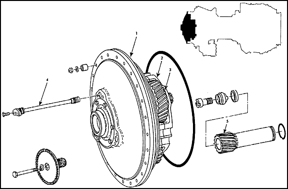
Figure 4.7. Output Reduction Carrier and Gear Assembly.
![]() b. Propeller reduction carrier and gear assembly used in the T53-L-701 engine utilizes a revolutionized reduction gear system called split power gearing. This type of power gear system has the ability to absorb greater torque loads, which permits the delivery of increased horsepower. Figure 4.8 is a cross sectional view of the split power reduction gear system. The power turbine speed reduction is accomplished within the split power gearing by primary and secondary drive systems, with power being transmitted to the propeller shaft through each of these systems.
b. Propeller reduction carrier and gear assembly used in the T53-L-701 engine utilizes a revolutionized reduction gear system called split power gearing. This type of power gear system has the ability to absorb greater torque loads, which permits the delivery of increased horsepower. Figure 4.8 is a cross sectional view of the split power reduction gear system. The power turbine speed reduction is accomplished within the split power gearing by primary and secondary drive systems, with power being transmitted to the propeller shaft through each of these systems.
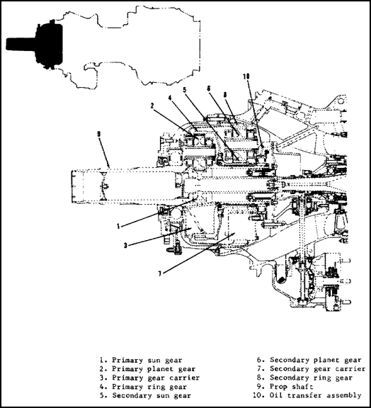
Figure 4.8. Split Power Reduction Gearing (T53-L-701).
4.11. ACCESSORY DRIVE ASSEMBLY
This assembly provides drive for both the N1-driven accessory gearbox and the N2-driven overspeed governor and tachometer. The numbers in parentheses in the following paragraphs are used in figure 4.9 to show the accessory gear drives.
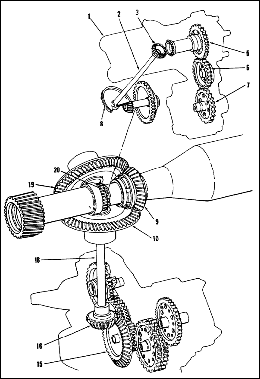
Figure 4.9. Accessory Drives.
N1 drive is provided from a pinion gear (9) mounted on the forward end of the compressor rotor shaft, driving two bevel gears (10 and 19) located within the accessory gear carrier. The bevel gear located at the six o'clock position within the carrier, being the accessory gearbox drive gear (10), is splined internally to accept the accessory gearbox shaft (18). This drive shaft connects the gear carrier to the accessory gearbox through the 90° pinion gear (16) which in turn is splined directly to the starter-generator drive gear (15). The starter-generator drive gear provides drive to all subordinate gears located within the accessory gearbox housing.
The power takeoff drive is provided through the second bevel gear (19) located within the accessory gear carrier, and it is used to drive airframe accessories.
The N2-driven overspeed governor and tachometer drive gearbox (1) receives its drive from a spur gear (20) pressed to the power shaft aft of the sun gear. This gear engages the N2 drive and driven gear package (8) located within the accessory gear carrier. This package, a series of three gears, provides an internally splined drive for the drive shaft (2) which passes up through the ten o'clock inlet housing strut and into the gearbox (1).
The drive shaft then engages the internal splines of the upper drive gear (3) which provides drive to the tachometer gear (5). This gear meshes directly with an idler gear (6) which in turn transmits the drive to the combination torquemeter boost pump and overspeed governor drive gear (7).
![]() a. N1 accessory drive gearbox assembly, shown in figure 4.10, is mounted on the underside of the engine inlet housing and is driven through bevel gears from the front end of the compressor rotor. Drive pads are provided on rear of the gearbox for the fuel control, the starter-generator, and the gas producer (N1) tachometer generator. The gearbox front side has mounting for the rotary oil pump, and also has an unused drive pad with connection for the torquemeter pressure transmitter vent line. Oil scavenge lines are connected at right rear on the gearbox which is an oil collector sump, kept practically empty by the pump. A chip detector plug is located in the lower right side, and the oil filter is on the left side.
a. N1 accessory drive gearbox assembly, shown in figure 4.10, is mounted on the underside of the engine inlet housing and is driven through bevel gears from the front end of the compressor rotor. Drive pads are provided on rear of the gearbox for the fuel control, the starter-generator, and the gas producer (N1) tachometer generator. The gearbox front side has mounting for the rotary oil pump, and also has an unused drive pad with connection for the torquemeter pressure transmitter vent line. Oil scavenge lines are connected at right rear on the gearbox which is an oil collector sump, kept practically empty by the pump. A chip detector plug is located in the lower right side, and the oil filter is on the left side.
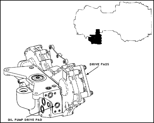
Figure 4.10. N1 Accessory Drive Gearbox.
![]() b. N2 overspeed governor and tachometer drive assembly, shown in figure 4.11, is a gearbox mounted on the engine inlet housing at the upper left side and is driven from the power shaft. The drive assembly provides mounting and drive pads for the power turbine (N2) tachometer generator and the torquemeter boost pump, (except on the T53-L-701) and also drives the fuel control overspeed governor. A relief valve, on the drive housing, allows adjustment of torquemeter oil pressure. An internal filter and metering cartridge lubricates the gear train.
b. N2 overspeed governor and tachometer drive assembly, shown in figure 4.11, is a gearbox mounted on the engine inlet housing at the upper left side and is driven from the power shaft. The drive assembly provides mounting and drive pads for the power turbine (N2) tachometer generator and the torquemeter boost pump, (except on the T53-L-701) and also drives the fuel control overspeed governor. A relief valve, on the drive housing, allows adjustment of torquemeter oil pressure. An internal filter and metering cartridge lubricates the gear train.
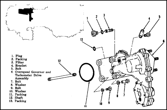
Figure 4.11. N2 Overspeed Governor and Tachometer Drive Assembly.
4.12. COMPRESSOR ASSEMBLY
The compressor and impeller housings, figure 4.12, consist of two matched halves constructed of cast magnesium and coated with HAE like the inlet housing assembly. The compressor housings provide alignment and support between the inlet housing forward and the diffuser housing aft. The housings enclose the five-stage axial compressor and the single-stage centrifugal compressor impeller. The stator vanes are located in lands (areas) between the compressor rotor disks when the housings are installed. The stators convert air velocity, from the rotating compressor, into pressure. The stators also direct airflow, at the proper angle, on to the following set of rotating compressor blades. The fifth stator vane assembly includes a row of exit guide vanes which direct airflow on to the centrifugal compressor impeller.
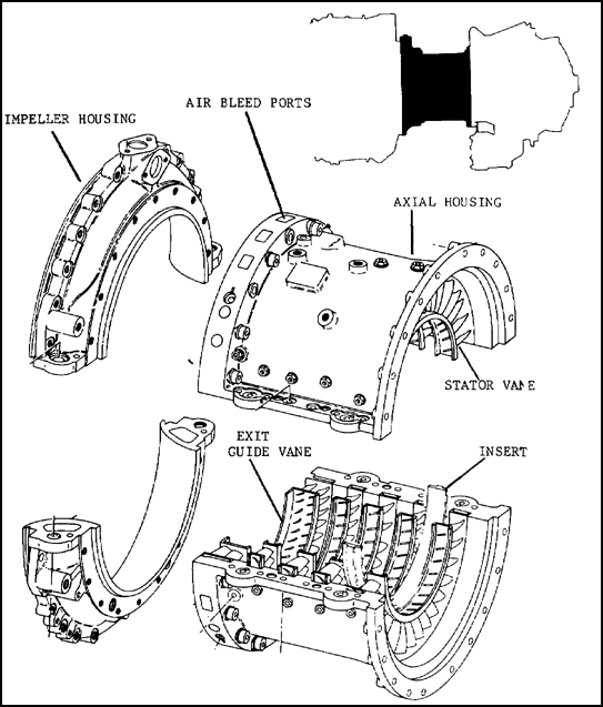
Figure 4.12. Compressor and Impeller Housing.
Stainless steel inserts are mounted between the stator vane rows of stages two through five to reduce compressor housing erosion from sand and foreign objects. At the rear of the axial compressor housings, a series of machined passages are provided to allow bleeding of compressor air. This bleeding of air is controlled by an interstage airbleed system. The centrifugal impeller housings have a hollow core which allows compressor bleed air to flow through them to the customer bleed air and anti-icing systems.
Externally the housing provides mounting points for limited engine and airframe accessories. Because of the structural support provided by the compressor housing, only one half may be removed at a time.
The dual compressor rotor assembly, figure 4.13, consists of five axial compressor rotor disks and one centrifugal impeller. The axial compressor blades are mounted in dovetail slots, machined into the rotor disks. Roll pins and lock plates, which act as shims, secure the blades to the disk. The centrifugal impeller is constructed of titanium for a high strength-to-weight ratio. The compressor rotor assembly is attached to the rear shaft and connects to the gas producer turbine. The hollow steel powershaft passes through and rotates independently of the compressor rotor. Splines on the forward end of the powershaft mate with the sun gearshaft that drives the output reduction gears. Splines at the aft end of the powershaft mate with the power turbine. The powershaft is supported at the forward end, within the inlet housing, by a roller type bearing. The aft end of the shaft is supported along with the power turbines (N2) by the No. 3 and 4 main bearings.
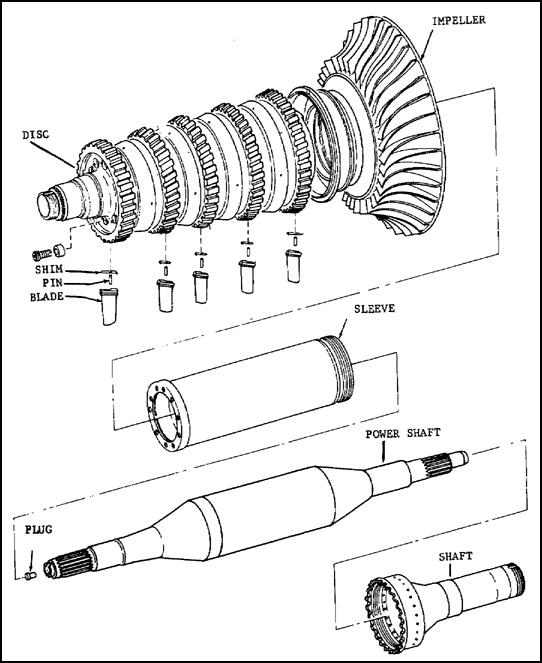
Figure 4.13. Compressor Rotor Assembly.
4.13. DIFFUSER HOUSING ASSEMBLY
The diffuser assembly housing shown in figure 4.14 is made of steel and is located aft of the compressor section.
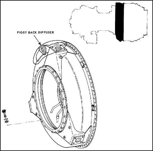
Figure 4.14. Diffuser Housing.
The diffuser receives high velocity air from the tip of the centrifugal impeller. The function of the diffuser is the decrease velocity and increase air pressure in this area. Air pressure at the diffuser discharge is at its highest value, with air temperature in the vicinity of 500° F. The diffuser also provides a means for bleeding a portion of the high temperature air for required engine and airframe use, such as engine anti-icing and cockpit heat. Later versions have an external air manifold, known as a piggyback diffuser, where air is extracted for use as required.
Externally, the diffuser provides engine mounting points at the four, eight, and twelve o'clock positions. Hoisting provisions are incorporated in the top or twelve o'clock mount. A port for extracting pressurized air for use as the pneumatic force for operation of an interstage bleed system actuator is provided at the three o'clock position. Mounting points for required engine accessories are provided on the external housing.
4.14. COMBUSTOR TURBINE ASSEMBLY
Located aft of the diffuser housing, the combustor turbine assembly consists of the combustion chamber housing and liner, gas producer turbines, power turbines, and exhaust diffuser. The combustor assembly is an external annular reverse-flow type. Although this design increases the diameter of the engine to a degree, it significantly reduces its overall length. It is classified an external annular reverse-flow type, in that the circular combustion chamber is located outside of and encloses the turbine area.
As shown back in figure 4.2, compressed air flowing aft from the diffuser enters the combustor (25 percent primary air) and mixes with fuel and supports combustion, within the combustion liner. The hot expanding gas flows forward within the liner; it is diluted and cooled by the remaining compressed air (75 percent secondary air).
Flow direction is changed again to the rear by the stationary deflector mounted within the diffuser inner housing. The gases then flow through the gas producer nozzles which greatly accelerate the gas stream and direct it onto the gas producer turbine (N1). The N1 turbine extracts approximately 60 percent of the energy to rotate the compressor assembly. The gases still possessing energy are again accelerated as they pass through the power turbine N2 nozzles. The gas stream is then directed onto the power turbines where most of the remaining gas energy is extracted to rotate the N2 power shaft.
The gases are then directed into the exhaust diffuser, and an average temperature of the gas stream is measured in this area (station 9, in figure 4.4). Although this temperature is much lower than that existing in the turbine inlet area (station 5, in figure 4.4), it is relative and indicative of the temperature at station 5. The fuel control automatically programs fuel flow, so the maximum turbine inlet temperature is not exceeded during normal operation.
![]() a. Combustion chamber housing. The T53 has an annular combustion housing which is constructed of steel. A flange at the forward end mates with the aft flange of the compressor diffuser housing. It is at this point that the engine is split to perform a hot-end inspection. A combustion chamber drain valve is located at the 6 o'clock position. This valve is spring loaded in the open position to drain any unburned fuel from the combustor during engine shutdown after a false or aborted start. During engine operation, compressed air flowing through the combustion chamber automatically closes the valve when chamber pressure exceeds outside pressure by approximately 2 psi. If the drain valve fails to close during engine operation a power reduction from air loss will occur. The stainless-steel, annular, combustion chamber liner is shown in figure 4.15. The liner contains a series of holes and louvers which vary in size, regulate the flow of pressurized air into the inner area to support combustion, and form a cooling air blanket on the liner surface. The T53-L-13 and later version have twenty-two swirl cups on the aft end that provide fuel nozzle access into the burner zone. Slots in the swirl cups direct airflow in a pattern to provide proper fuel atomization and flame control.
a. Combustion chamber housing. The T53 has an annular combustion housing which is constructed of steel. A flange at the forward end mates with the aft flange of the compressor diffuser housing. It is at this point that the engine is split to perform a hot-end inspection. A combustion chamber drain valve is located at the 6 o'clock position. This valve is spring loaded in the open position to drain any unburned fuel from the combustor during engine shutdown after a false or aborted start. During engine operation, compressed air flowing through the combustion chamber automatically closes the valve when chamber pressure exceeds outside pressure by approximately 2 psi. If the drain valve fails to close during engine operation a power reduction from air loss will occur. The stainless-steel, annular, combustion chamber liner is shown in figure 4.15. The liner contains a series of holes and louvers which vary in size, regulate the flow of pressurized air into the inner area to support combustion, and form a cooling air blanket on the liner surface. The T53-L-13 and later version have twenty-two swirl cups on the aft end that provide fuel nozzle access into the burner zone. Slots in the swirl cups direct airflow in a pattern to provide proper fuel atomization and flame control.

Figure 4.15. Combustion Chamber Liner.
![]() b. Turbine assembly. As the gases flow rearward from the defector, item 1 in figure 4.16, they contact the first stage gas producer turbine nozzle. The gases are accelerated by the nozzles to impinge upon the open tip blades of the N1 turbine, causing them to rotate at high speed in a counterclockwise direction. As the gases pass from the trailing end of the blades, an additional force is imparted to the turbine by the reaction to this flow.
b. Turbine assembly. As the gases flow rearward from the defector, item 1 in figure 4.16, they contact the first stage gas producer turbine nozzle. The gases are accelerated by the nozzles to impinge upon the open tip blades of the N1 turbine, causing them to rotate at high speed in a counterclockwise direction. As the gases pass from the trailing end of the blades, an additional force is imparted to the turbine by the reaction to this flow.
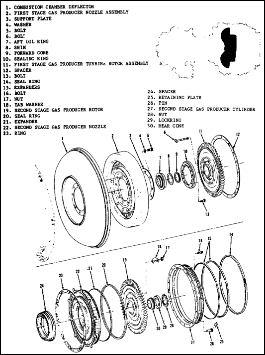
Figure 4.16. Gas Producer Assembly, N1.
The first stage gas producer turbine (GPl) and the second stage gas producer turbine (GP2) are mechanically joined together and rotate as one assembly (N1). The dual turbine design in later versions of the T53 permits more lightly loaded turbine blades than previous single turbine models and has a power output increase of 20%.
As the gases flow from the GP2 they pass on to the first stage power turbine nozzle (PT1). The gases are again accelerated and flow across the two N2 power turbines. Both turbine rotors have tip shrouded blades to prevent air losses and excessive vibrations. The power turbines are supported at the aft end by No. 3 (roller) and No. 4 (ball) main bearings. An N2 power turbine assembly is shown in figure 4.17.
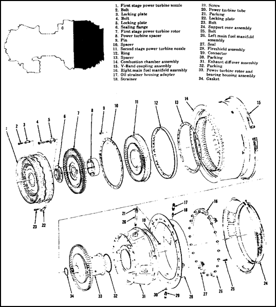
Figure 4.17. N2 Power Turbine.
![]() c. Exhaust diffuser. The welded steel diffuser, shown in figure 4.18, forms a divergent flow path for the exhaust gases. The diffuser consists of an inner and outer housing separated by four hollow struts. It is mounted to the aft inner flange of the combustor housing. Support for the aft section of the diffuser is provided by a support cone, 20 back in figure 4.1, that is secured by a "V" band coupling to the aft outer flange of the combustor housing. Located between the exhaust diffuser and support cone is a stainless steel fire shield, 19 in figure 4.1. During operation ambient air flows between the outer and mid cones of the diffuser. This air passes through a series of holes on the forward area of the outer cone and into the chamber formed by the diffuser and the fire shield. Ambient air then lows through the hollow struts to cool the bearing housing mounted within the diffuser and aft face of the power turbine (PT2). Mounts for an exhaust gas temperature harness are located on the diffuser midcone. The aft flange on the diffuser midcone is the mounting point for an airframe furnished tailpipe. The tailpipe routes the exhaust gas stream to the atmosphere.
c. Exhaust diffuser. The welded steel diffuser, shown in figure 4.18, forms a divergent flow path for the exhaust gases. The diffuser consists of an inner and outer housing separated by four hollow struts. It is mounted to the aft inner flange of the combustor housing. Support for the aft section of the diffuser is provided by a support cone, 20 back in figure 4.1, that is secured by a "V" band coupling to the aft outer flange of the combustor housing. Located between the exhaust diffuser and support cone is a stainless steel fire shield, 19 in figure 4.1. During operation ambient air flows between the outer and mid cones of the diffuser. This air passes through a series of holes on the forward area of the outer cone and into the chamber formed by the diffuser and the fire shield. Ambient air then lows through the hollow struts to cool the bearing housing mounted within the diffuser and aft face of the power turbine (PT2). Mounts for an exhaust gas temperature harness are located on the diffuser midcone. The aft flange on the diffuser midcone is the mounting point for an airframe furnished tailpipe. The tailpipe routes the exhaust gas stream to the atmosphere.
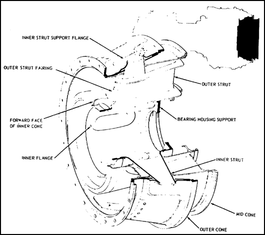
Figure 4.18. Exhaust Diffuser.
4.15. DESCRIPTION OF FUEL SYSTEM
The T53 series engines are designed to operate primarily on MIL-J-5624 grade JP-4 fuel. The fuel system consists of the components shown in figure 4.19.
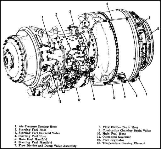
Figure 4.19. Fuel System Components.
Fuel flow is maintained between components by flexible or rigid lines. An airframe-mounted boost pump supplies fuel to the fuel control inlet port. During the starting sequence fuel flows through an external line from the hydromechanical fuel control to the starting fuel solenoid inlet, shown in figure 4.20. The cockpit-controlled solenoid is a two-position valve electrically opened and spring loaded closed. With the valve energized to the open position, fuel flows through an external line to the starting fuel manifold. The start fuel manifold is a two-piece assembly with four rigidly-mounted starting fuel nozzle attaching points. Fuel flows into the starting nozzles located at the 2, 4, 8, and 10 o'clock positions at the rear of the combustor housing. The nozzles inject atomized fuel into the combustion chamber during the starting sequence. The following subparagraphs discuss the two fuel flow systems.
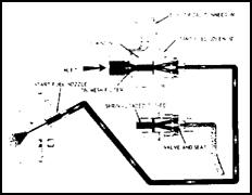
Figure 4.20. Starting Fuel Flow Sequence.
![]() a. Normal fuel flow. The fuel flow continues in the fuel control from the main metering valve to the main system outlet port.
a. Normal fuel flow. The fuel flow continues in the fuel control from the main metering valve to the main system outlet port.
An external line carries the fuel from the port to the flow divider and dump-valve assembly. With the introduction of the atomizing combustor configuration with dual orifice nozzles, a flow divider dump-valve assembly was installed to achieve correct fuel atomization throughout the engine operating range.
The flow divider meters fuel to the engine nozzles according to a predetermined schedule of secondary flow versus primary flow. A dump valve is incorporated as an integral unit to drain the fuel trapped in the manifold and fuel lines when the engine is shut down. The flow divider and dump valve assembly is designed to function with fuel pressure up to 1,200 psi with an ambient temperature of 250° F (121° C) and a fuel supply temperature from -65° F (-54° C) to 200° F (93° C). The flow divider assembly, shown in figure 4.21 has a lower housing containing the dump valve and an upper housing for the flow divider. These housings are machined from corrosion resistant steel casting, and sharp edges are maintained on all metering slots and ports.
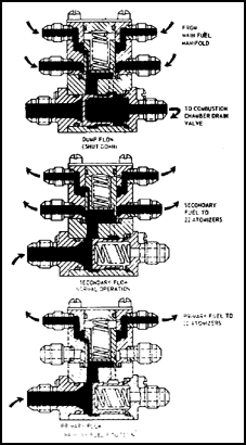
Figure 4.21. Fuel Flow Divider.
When fuel pressure at the inlet reaches a predetermined value, the dump valve plunger moves toward the closed position, allowing fuel to enter the flow divider valve. When the inlet pressure has reached the minimum engine operating pressure, the dump valve plunger is in the fully closed position. The drain valve seal prevents fuel from the primary and secondary manifolds from draining.
Fuel passes the flow divider series orifice in the flow divider plunger en route to the primary manifold, creating a pressure drop. This pressure drop across the orifice is sufficient to move the plunger off its stop. As the plunger is displaced, the secondary flow metering ports in the plunger are progressively opened, allowing fuel to pass to the secondary manifolds. From the flow divider, fuel flows through primary and secondary lines to the main fuel manifold assembly shown in figure 4.22.
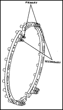
Figure 4.22. Fuel Manifold.
From the flow divider, fuel flows through primary and secondary lines to the main fuel manifold assembly. The manifold is a two-section, dual-channeled assembly with eleven outlets in each section. Each manifold half is interchangeable, requiring only a minor hardware adjustment to make the change. The 22 fuel atomizers are attached directly to the manifolds, which discharge the atomized fuel into the combustion chamber.
The fuel atomizer, as shown in figure 4.23 is a dual orifice injector designed to accommodate the separate primary and secondary fuel flow functions. The separate orifices spray fuel into the combustion chamber through the action of the flow divider. Fuel entering the primary section of the atomizer passes through the primary screen and continues to flow through the center of the nozzle to the swirl chamber located internally in the head of the nozzle. Here it passes through three swirl slots and is discharged into the combustion chamber at a 90° spray angle. The fine spray density established by the primary slots is required to start and run the engine. Higher N1 speeds require additional fuel and a heavier density spray pattern; therefore, secondary fuel is introduced through the nozzle at speeds above 32% N1. The secondary flow enters the outer shell of the nozzle and passes through the secondary screen and into the secondary swirl slots. The secondary swirl slots, being slightly larger in size than the primary swirl slots, allow a greater volume of fuel to be discharged into the combustor. The combination of primary and secondary flow which is delivered to the combustor at an-optimum spray angle of 90° is sufficient to operate the engine at all power settings above 32% N1.
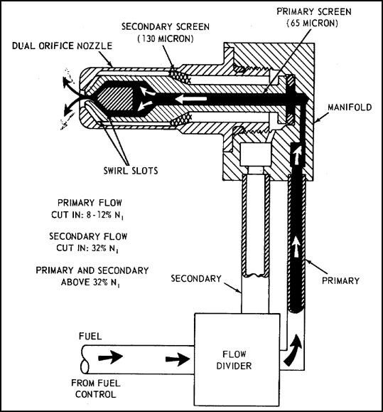
Figure 4.23. Fuel Atomizer.
To further atomize the fuel entering the combustor liner, swirl cones located at the aft end of the combustor liner assembly allow combustion air to enter the liner and swirl in the opposite direction to that of the fuel being injected by the atomizer. This additional swirling air establishes a definite flame pattern at the end of each atomizer. Additionally, air is routed through the air shroud to cool the atomizers and assist in establishing this flame pattern. When fuel flow is cut off at engine shutdown, the inlet pressure falls below the dump-valve opening pressure, and the dump-valve plunger is moved by its spring to the fully open position. The fuel in the primary manifold then flows to drain through the main flow passage between the flow divider and drain valve. The secondary manifold is drained via a small drain port in the upper housing leading into the dump-valve cavity.
![]() b. Manual fuel flow. The manual or emergency fuel flow sequence is the same as normal fuel flow sequence except for the fuel-control changeover valve. When the changeover valve is actuated to the manual position, fuel is redirected to the manual-system metering valve, which is mechanically linked to the main power control in the cockpit. This flow path bypasses the main metering valve. Other than that, the manual fuel-flow sequence is the same as the normal. The fuel system on the T53-L-13 is similar to the one on the T53-L-701. However, the T53-L-701 turboprop engine has a fuel heater to prevent fuel from icing by using engine lubricating oil to heat the fuel. The fuel heater supplies fuel in temperature ranges between 35 to 70° F when fuel inlet temperatures are in the -65 to -70° F range.
b. Manual fuel flow. The manual or emergency fuel flow sequence is the same as normal fuel flow sequence except for the fuel-control changeover valve. When the changeover valve is actuated to the manual position, fuel is redirected to the manual-system metering valve, which is mechanically linked to the main power control in the cockpit. This flow path bypasses the main metering valve. Other than that, the manual fuel-flow sequence is the same as the normal. The fuel system on the T53-L-13 is similar to the one on the T53-L-701. However, the T53-L-701 turboprop engine has a fuel heater to prevent fuel from icing by using engine lubricating oil to heat the fuel. The fuel heater supplies fuel in temperature ranges between 35 to 70° F when fuel inlet temperatures are in the -65 to -70° F range.
4.16. INTERNAL COOLING AND PRESSURIZATION SYSTEM
The internal cooling system provides cooling air to the internal engine components and pressurizes the number one, two, and three main bearing seals. Cooling and pressurization air is obtained from five parts of the engine. The following numbers in parentheses, such as (1), (2), and so on in the discussion, correspond to similar numbers in figure 4.24 and refer you to that particular portion of the engine. Air flows down through the fourth stage spacer (1) into the area between the compressor rotor sleeve and the rotor disk inside diameters, then forward to the first stage rotor disk where it is bled back into the compressor airstream through holes in the first stage spacer. This airflow cools the three aluminum disks in the compressor rotor assembly. Compressed air bled from the tip of the centrifugal compressor impeller (2) cools the forward face of the diffuser housing and pressurizes the No. 2 bearing forward seal, and continues rearward through transfer tubes in the bearing housing to pressurize the No. 2 aft oil seal. It also passes through a series of holes in the rear compressor shaft into the space between the rotor assembly and the power shaft. At this point, it separates into three flow paths. Part of the compressed air, used for seal pressurization, flows forward and through a series of holes in the compressor front shaft. This air fills the area between the carbon elements of the No. 1 bearing seal. The intershaft seal, located forward of the No. 1 bearing, prevents flow of pressurized air into the inner inlet housing area. A portion of this compressed air flows aft over the power shaft and emerges at the aft end of the rear compressor shaft to cool the rear face of the second gas producer (GP) rotor, the forward face of the first power turbine (PT) rotor, and the first stage PT nozzle. The air then passes into the exhaust stream. The remainder of the compressed air flows through a series of holes in the power shaft. This air flows aft, inside the power shaft, through holes drilled in the hollow power-shaft through bolt, and into the interior of the second PT rotor assembly. Air then passes through a series of holes in the turbine hub and the turbine spaces to cool the rear surface of the first PT rotor assembly, the forward surface of the second PT rotor assembly, and both faces of the second PT nozzle.
Compressed air, bled through slots in the mating surfaces of the combustion chamber deflector and the air diffuser (3) cools the forward face of the deflector and the No. 2 bearing housing. Then the air is split into paths to cool the blade roots of the first stage GP rotor assembly. The air then flows through holes in the inside diameter of the GP turbine spacer to cool the hub area of the rear face of the first GP turbine and the forward face of the second GP turbine. The air then flows rearward where it joins the cooling air being discharged from the aft end of the compressor shaft where it is expelled into the exhaust stream.
Compressed air is then directed through the first stage GP nozzle and cylinder assembly (4) to cool the rear face of the first stage GP rotor and then into the exhaust stream.
Ambient air is used to cool the No. 3 and No. 4 bearing housing. The air enters the exhaust diffuser struts (5) and moves forward between bearing housing walls to cool the rear face of the second stage PT rotor assembly. As the ambient air passes the forward face of the No. 3 bearing seal, it helps pressurize the seal.
4.17. VARIABLE INLET GUIDE VANE SYSTEM
To ensure a compressor surge margin, the angle of incidence of the inlet air to the first compressor rotor must be within the stall-free operating range of the compressor blades, and, because this stall-free operating range varies with compressor speed (N1), it is necessary to vary the angle of attack with changes in N1 speed. This is done by varying the angle of the inlet guide vanes. The variable inlet guide vanes (VIGV) are located in front of the first compressor rotor as shown in figure 4.5.
At low N1 speeds, a high angle of attack is required, while at higher N1 speeds, the angle of attack decreases. Refer to the blocks in figure 4.25 for the angle of attack at high and low N1 speeds.

Figure 4.25. Variable Inlet Guide Vane Angle of Attack.
The VIGV's are positioned by the inlet guide vane actuator pilot valve, located in the fuel control, which monitors N1 speed and compressor inlet temperature (T1). While setting the desired position of the VIGV's, the actuator relays their position back to the fuel control through an external feedback control rod to nullify the fuel pressure signal so that at any steady-state N1 speed between 80 and 95 percent, the inlet guide vanes will assume a constant position. The VIGV actuator is mounted on the right side of the compressor housing assembly, shown in figure 4.26. The actuator is controlled by main fuel pressure from the fuel control. Two fuel lines carry the fuel from the fuel control to the VIGV actuator. This fuel pressure acts upon the piston inside the actuator to move the VIGV's. The VIGV's are positioned by the inlet guide vane actuator control rod through a synchronizing ring.
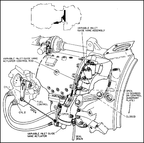
Figure 4.26. Variable Inlet Guide Vane System.
4.18 INTERSTAGE BLEED SYSTEM
The interstage bleed system, shown in figure 4.27, consists of a bleed band, an actuator assembly, and air hoses and connectors. The function of the system is to improve compressor acceleration characteristics. The system automatically unloads the compressor of a small amount of compressed air (about one tenth) during the period in the engine acceleration cycle when faster compressor acceleration is more desirable than the slight loss in engine power due to the air bleed.
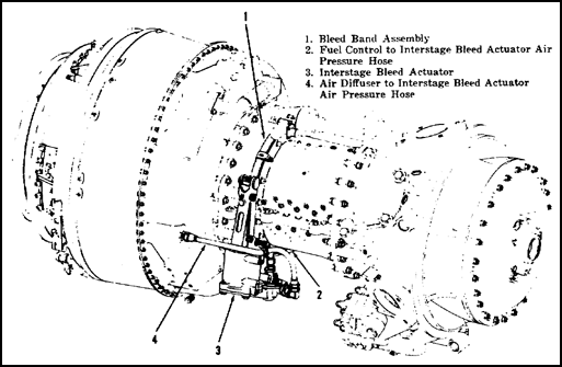
Figure 4.27. Interstage Bleed System, External Components.
The air bleed actuator, shown in figure 4.28, operates by compressor discharge air (P3)which is extracted from a port on the right side of the air diffuser housing.
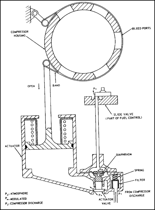
Figure 4.28. Interstage Bleed System, Cutaway View.
The air entering the actuator assembly passes through a filter to the underside of the relay valve diaphragm. A small portion of this air, which is under the diaphragm, is bled through an orifice in the base of the relay valve assembly to an external line which directs it to a slide valve located on the fuel regulator housing.
With the slide valve in the open position, this air (Pm) is vented overboard, reducing pressure at the top surface of the diaphragm. Simultaneously, air is being bled overboard through the open actuator valve; this reduces pressure at the bottom surface of the diaphragm. This equalization of pressure on both surfaces of the diaphragm causes it to remain in a neutral position holding the relay valve in its open position. With the actuator valve open, the majority of the P3 air that enters the actuator assembly is vented to the atmosphere. When the P3 pressure is vented, the actuator spring, located on top of the actuator piston, expands and pushes the piston downward. This causes the bleed band to open and remain open as long as the slide valve on the fuel control is in the open position.
When the slide valve is closed, it follows then that the bleed band will be closed. This is accomplished by a buildup of pressure on the top side of the relay valve diaphragm which forces the relay valve down, closing off the overboard vent. With the overboard vent closed, the P3 pressure is now routed into the actuator piston assembly to move upward. This causes the bleed band to close around the compressor bleed ports.
The entire sequence of operation is controlled by the fuel control which senses gas producer (N1) speed, fuel flow and pilot demand, therefore ensuring proper opening and closing of the interstage air bleed.
4.19. ANTI-ICING SYSTEM
The engine anti-icing system, shown in figure 4.29, supplies hot air, under pressure, to prevent icing of the inlet housing areas and inlet guide vanes when the engine is operating under icing conditions. Pressurized hot air from the air diffuser flows through the holes in the trailing edge of the diffuser vanes and collects in the bleed air diffuser manifold, where it is passed to an external bleed-air manifold located at the 1 o'clock position on the diffuser housing. An elbow and tube are connected to the external bleed-air manifold and to an adapter located on top of the impeller housing. The tube and elbow pass air through the impeller housing to the hot air solenoid valve.
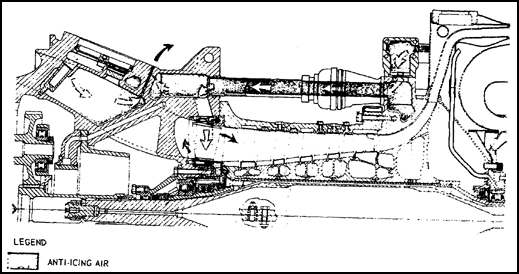
Figure 4.29. Anti-icing System Diagram.
The hot air solenoid valve is mounted on top of the compressor and impeller housing. The solenoid-operated valve controls the flow of anti- icing hot air from the diffuser to the inlet housing. It is an electrically controlled, pneumatically operated, fail-safe valve and will open in the event of an electrical failure.
During engine operation, the solenoid is generally energized and the valve remains closed. When anti-icing air is needed, the solenoid is deenergized by activating a switch in the cockpit. This vents one side of the valve to atmospheric pressure, and the differential pressure between diffuser pressure and atmospheric pressure overcomes spring tension and allows anti-icing air to flow to the inlet area. The valve will anti-ice at gas producer speeds (N1) above flight autorotation (68% - 72% N1).
After leaving the hot air solenoid valve, anti-icing air flows forward through a tube into the port on top of the inlet housing. This anti-icing air is then circulated through five of the six hollow inlet housing support struts to prevent ice formation in the inlet housing area. Anti-icing air also flows into the rear of the inlet housing where it passes through the hollow inlet guide vanes to prevent icing. After passing through the inlet guide vanes, the air exits in front of the inlet guide vanes and flows into the compressor area. Hot scavenge oil, draining through the strut at the 6 o'clock position of the inlet housing prevents ice formation in the bottom of the inlet housing area.
4.20. DESCRIPTION AND OPERATION OF LUBRICATION SYSTEM
The engine lubrication system consists of the main oil pressure supply system and the oil scavenge system. The principal components of the lubrication system are the oil filter assembly, power-driven rotary oil pump, power-driven rotary boost pump, and associated oil lines and internal passages. Figure 4.30 shows the internal lubrication system for the T53-L-13. The operation of the oil system is covered in the following subparagraphs.
![]() a. Main oil pressure supply system. Engine lubricating oil is supplied from an aircraft-mounted oil tank. Oil enters the power-driven rotary oil pump, which is mounted on the N1 accessory drive gearbox, along with the main oil filter, shown in figure 4.31A. Filter oil is directed into two main flow paths. Oil is directed through internal passages in the inlet housing to supply lubricating oil to the front section of the engine, including the reduction gearing, torquemeter, accessory drive gearing, the No. 1 main bearing, and the power shaft forward bearing. The second oil path is through the external oil pressure lines to the rear section of the engine to lubricate the No. 2, 3, and 4 main bearings.
a. Main oil pressure supply system. Engine lubricating oil is supplied from an aircraft-mounted oil tank. Oil enters the power-driven rotary oil pump, which is mounted on the N1 accessory drive gearbox, along with the main oil filter, shown in figure 4.31A. Filter oil is directed into two main flow paths. Oil is directed through internal passages in the inlet housing to supply lubricating oil to the front section of the engine, including the reduction gearing, torquemeter, accessory drive gearing, the No. 1 main bearing, and the power shaft forward bearing. The second oil path is through the external oil pressure lines to the rear section of the engine to lubricate the No. 2, 3, and 4 main bearings.

Figure 4.31A(B)(C). Lubrication Flow Diagram.
In the inlet housing section, oil is directed through the accessory drive carrier flanges into the main oil transfer assembly located in the rear support flange of the carrier, as illustrated in figure 4.31(A). Oil from this passage is directed to the oil transfer assembly for forced-feed spray lubrication of the reduction gears through three oil transfer tubes. Oil flows through internal passages in the output reduction carrier liner, under pressure, to three jets in the liner. One jet sprays oil forward, lubricating the main output shaft bearing runner, the second lubricates the reduction gear forward bearing, and the third sprays aft, lubricating the output gear shaft bearing.
Oil from the transfer tube sprays against the output shaft plug deflector. This deflector is manufactured with a predetermined angle to splash the oil rearward, to lubricate the sun gear and power shaft splines. Three oil jets located 120 degrees apart in the main oil-transfer assembly, shown in figure 4.31(A), direct oil to the rear planetary support bearings. The main oil-transfer support assembly also houses an oil jet positioned so that high pressure oil is directed to impinge or the power shaft bearing runner, thus lubricating the bearing. Machined oil grooves in the accessory drive carrier assembly, illustrated in figure 4.31A(B), transport oil through an internal strainer to an oil nozzle located in the power shaft support bearing retainer. The oil nozzle has three machined jets. The first jet is positioned to lubricate the accessory drive pinion gear, the second jet is designed to lubricate the number one main bearing runner, and the third jet is positioned to lubricate the main bearing. Surplus oil from the number one main bearing and pinion gear also lubricates the accessory drive shaft support bearings. The number one main bearing and the accessory drive pinion gear are lubricated by oil from a transfer tube located in the accessory drive carrier assembly. Oil under a constant pressure from the transfer assembly lubricates the power shaft support bearing.
Oil from a third transfer passage is directed from the main transfer assembly up through an inlet housing strut to the power-driven rotary booster pump. This pump is mounted on the overspeed governor and tachometer drive assembly. The assembly includes a pressure regulating valve that governs the output pressure of the rotary torquemeter boost pump by circulating the excess pressurized oil back to the inlet housing. The pressurized oil from the rotary booster pump is directed back through an inlet housing strut to the torquemeter cylinder, shown in figure 4.31A(C).
An offset passage in the overspeed governor mounting flange directs engine oil to the strainer and metering cartridge in the overspeed governor gearbox. An additional transfer passage from the main transfer support assembly directs oil through internal passages in the inlet housing to the power takeoff mounting flange.
This oil passes through a strainer and metering orifice, which lubricates accessories driven by the engine, mounted on the power takeoff. Oil flow to the rear section of the engine is supplied from an oil pressure port at the 5 o'clock position in the inlet housing through an external hose to a pressure manifold. The manifold is mounted on the forward face of the diffuser housing. Oil is directed from the bottom of the manifold through a strainer mounted on the diffuser housing, shown at L in figure 4.31B, to the No. 2 main bearing. Oil is directed from the top of this manifold through an external hose and strainer, shown in H in figure 4.31B, through the upper strut in the exhaust diffuser and directed through the power turbine oil tube at F in figure 4.31B. The oil tube consists of two jets; one directs oil to the forward face of the No. 4 bearing runner, and the second jet lubricates the aft face of the No. 3 bearing runner. Oil is also directed through a horizontal tube forward to the No. 3 bearing seal.

Figure 4.31B. Lubrication Flow Diagram.
![]() b. Oil scavenge system. All internal scavenge oil from the inlet housing section drains through a hollow support strut to the bottom of the inlet housing through a scavenge strainer and transfer tube, and into the accessory drive gearbox. Scavenge oil from the output reduction carrier and gear assembly flows by gravity into the hollow inlet housing struts.
b. Oil scavenge system. All internal scavenge oil from the inlet housing section drains through a hollow support strut to the bottom of the inlet housing through a scavenge strainer and transfer tube, and into the accessory drive gearbox. Scavenge oil from the output reduction carrier and gear assembly flows by gravity into the hollow inlet housing struts.
Scavenge oil from the No. 1 main bearing is pumped to the inlet housing struts by an impeller or paddle pump located on the rear of the bearing. Scavenge oil from the No. 2 main bearing flows through a scavenge oil tube, illustrated at G in figure 4.31B, in the diffuser housing and is directed to the accessory drive gearbox by an external scavenge oil hose assembly. Scavenge oil from the No. 3 and 4 bearings, as shown in figure 4.31B(F), flows through an oil tube that extends through the bottom of the exhaust diffuser and is directed to the accessory drive gearbox by an external oil scavenge hose assembly. The scavenge portion of the power-driven rotary oil pump returns scavenge oil from the accessory drive gearbox through the aircraft oil cooler to the aircraft oil storage tank.
The torquemeter shown in figure 4.32 is used on the T53-L-13; it is a hydromechanical torque-measuring device located in the reduction-gear section of the inlet housing. It uses boosted engine oil to measure engine torque effort; the measurement is read in the cockpit as torque oil pressure in psi. Although this system uses engine oil, it is not a part of the lubrication system. The following numbers in parentheses correspond to the numbers in figure 4.32.
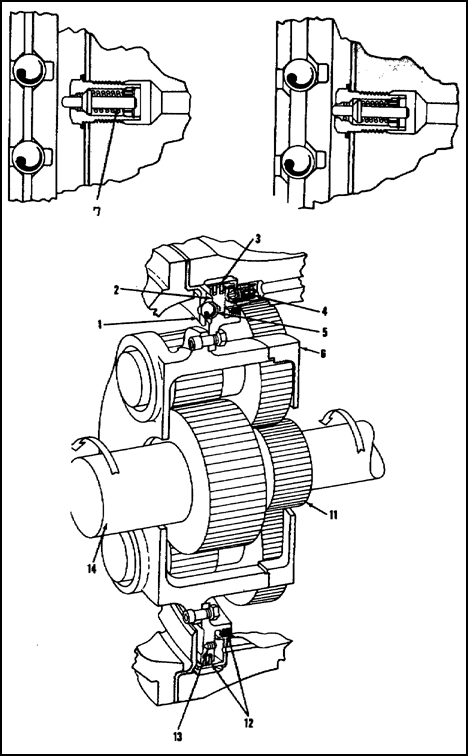
Figure 4.32. Torquemeter Diagram.
The mechanical portion of the torquemeter consists of two circular plates. One is attached to the inlet housing and is identified as the stationary plate (1). The second, or movable plate (2) is attached to the reduction gear assembly (6). The movable plate contains front and rear torquemeter sealing rings (12), which enable it to function as a piston in the rigidly mounted cylinder (3). The cylinder assembly houses the variable-opening torquemeter (poppet) valve (4). The movable plate maintains the fixed-orifice metered bleed (13), which functions in relation with the poppet valve. The movable plate is separated from the stationary plate by steel balls (5) positioned in matched conical sockets machined in the surfaces of both plates. When the engine is not operating, the torquemeter movable plate is a position forward and clear of the torquemeter valve plunger, allowing the spring-loaded valve to remain in the closed position. With the engine operating and a load applied to the output shaft (14), the torque developed in the engine to drive the shaft is transmitted from the sun gear (11) through the reduction gear assembly. The attached movable plate tends to rotate with the assembly. However, this mechanically limited radial movement positions the steel balls against the conical sockets of both plates, resulting in the movable plate being axially directed rearward in the assembly.
The plate, moving rearward, contacts the torquemeter valve plunger, opening the valve and allowing oil to flow into the cylinder. This contact is maintained during all engine operation, and the size of the valve opening varies as the plate moves rearward or forward. As torque continues to increase and the torquemeter valve opens further, oil pressure increases in the cylinder but will not exceed the boost pump pressure because of the metered bleed (13).
The oil pressure developed in the cylinder exerts pressure against the piston (movable plate), restraining the rearward movement. With the engine operating in a steady-state condition the cylinder oil pressure and movement of the plate hold in an equalized position.
The pressurized oil from the torquemeter cylinder is also directed to the transmitter from a port at the 3 o'clock position of the inlet housing. The transmitter cancels the air pressure effect, resulting in a true torquemeter indication at the instrument in the cockpit.
A power-driven rotary (booster) pump, containing pressure and scavenge elements is mounted on and driven by the overspeed governor and tachometer drive assembly. Each element is an individual pumping unit and draws oil from a separate source. The pressure element receives engine lubricating oil and delivers it, at a boosted pressure, to the torquemeter valve. Excess oil flows back to the inlet side of the pump. A relief valve in the overspeed governor and tachometer drive assembly sets the power-driven rotary (booster) pump outlet pressure. The scavenge element receives oil from the overspeed governor and tachometer drive gear housing and delivers it to the oil return passages in the inlet housing assembly.
The Lycoming T53- L-7 01 uses an electric torquemeter system to monitor power output. The Avco Lycoming electric torquemeter is a refined torque measuring system which measures torque imposed on the engine power output shaft. The torque signal is a result of tension and compression stresses changing the magnetic reluctance of the shaft.
The torque system is comprised of five components and their interconnecting wiring. Two of these, the power supply and the indicator, are airframe mounted components and may be replaced at any time without recalibration. The remaining three, the power output shaft, the head assembly (transformer), and junction box, must be replaced only as a pre-calibrated set.
The transformer consists of one primary and two secondary windings. The primary generates a constant magnetic field which penetrates the transformer core attached to the primary sun gear. The voltage induced in the two secondaries varies with the tension and compression stresses imposed on the shaft. This difference in secondary voltage is transmitted through the junction box and is read on the cockpit indicator as psi of torque. Figure 4.33 is a cross section of the inlet housing to show relationship of power output shaft, torquemeter head assembly, and torquemeter junction box.
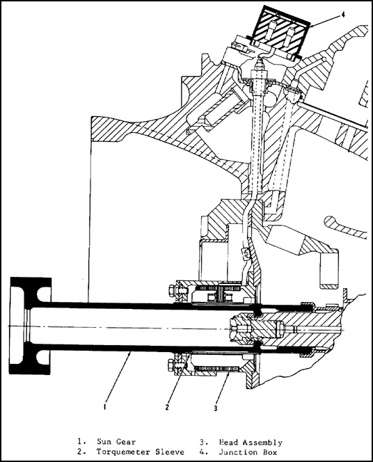
Figure 4.33. Torquemeter System (T53-L-701).
4.22. ELECTRICAL SYSTEM
The engine electrical system consists of the main wiring harness and connectors for electrical components as shown in figure 4.34. The airframe and engine wiring diagram is shown in figure 4.35. The following subparagraphs briefly discuss the operation of the engine electrical system.

Figure 4.34. Electrical System.

Figure 4.35. Electrical Wiring Diagram.
![]() a. Ignition system. The high-energy, medium-voltage, capacitor-discharge ignition system consists of an ignition-exciter unit, output leads, spark-splitter coil, and four surface-gap igniter plugs. The system is activated simultaneously with the start fuel solenoid valve and starter by a switch in the cockpit. The ignition system is used only for engine starting and not for sustaining combustion.
a. Ignition system. The high-energy, medium-voltage, capacitor-discharge ignition system consists of an ignition-exciter unit, output leads, spark-splitter coil, and four surface-gap igniter plugs. The system is activated simultaneously with the start fuel solenoid valve and starter by a switch in the cockpit. The ignition system is used only for engine starting and not for sustaining combustion.
Power from the 28v dc electrical system is stepped up in the exciter unit to 2,500 volts and discharged through igniter plugs in the combustion chamber at a spark rate of two to eight per second.
![]() b. Exhaust gas temperature harness. An exhaust thermocouple harness, consists of an electrical connector, a shielded manifold, and six thermocouples, as shown in figure 4.36.
b. Exhaust gas temperature harness. An exhaust thermocouple harness, consists of an electrical connector, a shielded manifold, and six thermocouples, as shown in figure 4.36.
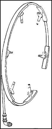
Figure 4.36. Exhaust Thermo-couple Harness.
The thermocouples are inserted through the exhaust diffuser into the exhaust gas flow. When heated by the exhaust gas, an electromotive force(emf) is generated. Any two dissimilar metals placed in contact with each other generate a small voltage if heated at that junction. The amount of voltage produced varies with the metals used and the temperature they are heated to. Electrically, the thermocouples are connected in parallel with each other. This results in an average temperature reading. If one thermocouple becomes inoperative an average reading of the remaining ones will result. The thermocouples and their leads are made of chromel and alumel. Chromel is an alloy of nickel and chromium. Alumel is an alloy of nickel, manganese, aluminum, and silicon. The accuracy of the thermocouple harness is +5° at 1292° F (700° C).
4.23. SUMMARY
The major engine assemblies are the inlet, accessory gearbox, compressor, diffuser, and combustor turbine assembly. The inlet housings on both the T53-L-15 and T53-L-701 have a propeller reduction gear assembly.
Fuel is metered by a hydromechanical fuel control to twenty-two atomizers. The fuel control has two modes of operation: normal, and manual fuel flow. The internal cooling and pressurization system provides cooling air to internal engine parts and pressurizes the main bearing seals. The engine has variable inlet guide vanes to ensure a compressor surge-free margin. The interstage bleed system automatically unloads the compressor of a small amount of air during engine acceleration. The anti-icing system supplies hot air, under pressure, to prevent icing of the inlet housing areas and inlet guide vanes. Oil is supplied for lubrication by the oil pressure supply system and is scavenged by the scavenge oil system. The torquemeter is a hydromechanical, torque-measuring device that indicates engine torque in psi. Ignition for starting is produced by a high-energy, medium-voltage, capacitor-discharge system. Exhaust gas temperature is measured by six thermocouples inserted in the exhaust gas flow.
GO TO:

