LESSON 4
| LESSON 4 | Testing, Inspection, Maintenance, and Storage Procedures. |
| TEXT ASSIGNMENT | Reference Text AL0993, paragraphs 3.1-3.15. |
| LESSON OBJECTIVE | To enable you to describe the procedures for testing, inspection, maintenance, and storage of aircraft gas turbine engines. |
| CREDIT HOURS | 2 |
Chapter 3
TESTING, INSPECTION, MAINTENANCE, AND STORAGE PROCEDURES
3.1. INTRODUCTION
The information in this chapter is important to you because of its general applicability to gas turbine engines. The information covers the procedures used in testing, inspecting, maintaining, and storing gas turbine engines. Specific procedures used for a particular engine must be those given in the technical manual (TM) covering that engine
3.2. THE TEST CELL
Before any engine is shipped to the user, the manufacturer or overhaul facility has test-run the engine in a test cell to ensure quality control. The test cell building is usually constructed of concrete and contains both the control room and engine room, although in some test cells only the control room is enclosed. A typical test cell and a control room are shown in figure 3.1. If an engine fails during a test run or does not perform to the standards set by the manufacturer, that engine and a specified number of previous engines are disassembled to check for faults.
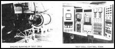
Figure 3.1. Test Cell Control Room.
Ground operation, or testing of an engine may also be performed in the mobile engine test unit (METU). The mobile trailer unit contains engine testing equipment similar to that available in an engine test cell. The mobile unit increases engine availability by eliminating most of the need to return engines to an overhaul depot.
Test-cell instrumentation usually includes temperature and pressure gages to monitor engine performance. The engine is run in the test cell with the same demands placed upon it as if it were installed in an aircraft. The performance of any engine is considerably influenced by changes in ambient temperature and pressure, because of the way these conditions affect the weight of the air entering the engine. To compare the performance of similar engines on different days, under different atmospheric conditions, a given engine's performance must be corrected to the standard day condition of 29.92 inches of mercury and 59° F.
During the initial run after assembly, or after extensive maintenance or overhaul, engine statistics are recorded on a test log. This log sheet remains with the engine historical records until such time as another data sheet is completed.
During testing, any problem that would limit the engine's performance, such as exhaust gas temperature, torque, fuel flow, or maximum speed, is corrected. In addition, oil temperature, bearing scavenge-oil temperature, seal leakage, and oil consumption must be within established limits. These tests are usually performed under other than standard day conditions, and data will then be computed to a standard day rating by using the charts and tables in the engine manual. This new information is entered on the engine test log sheet as shown in figure 3.2 and becomes a permanent part of the engine records.
3.3. VIBRATION EQUIPMENT
High-frequency vibrations must be detected and eliminated because they can cause mechanical failure and extensive engine damage. This paragraph discusses the cause of vibrations and the equipment to analyze vibrations. The main source of vibration in the gas turbine engine is the imbalance of rotating parts. Imbalance is caused by an uneven distribution of weight and is measured in inch-grams or inch-ounces. An inch-gram is one gram of unbalanced weight concentrated one inch from the center of a rotating part. When an unbalanced part is rotated, a force is generated. This force is a product of the amount of imbalance and rotating speed.
To analyze this force, a vibration transducer is used; this is a miniature generator. When attached to a vibrating object it generates an electrical signal that is proportional to the force being analyzed. The signal is sent to a meter that amplifies the signal so it can be conveniently read. The meter has four input channels that independently accommodate a signal from a transducer. The meter, shown in figure 3.3, also has connections for an oscilloscope or an oscillograph for closer examination. Filters are available to eliminate low frequency vibrations for a clearer picture of the higher, more damaging vibration signals being studied.
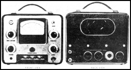
Figure 3.3. Vibration Meter.
Gas turbine vibration sources fall in two general classifications: forced vibration, and externally excited vibration.
Forced vibration is due to unbalanced rotating parts. The uneven weight distribution that causes the imbalance may be due to manufacturing methods, or improper assembly of components without regard for the balance in relation to other components. Other engine imbalances may be the result of a bent shaft, or a distortion caused by temperature.
Externally excited vibrations are caused by means other than an imbalance of rotating engine components. They may be caused by associated accessories, such as loose engine mounts or clamps, improperly mounted accessories, engine-driven transmissions, or airframe structure members.
An engine vibration test is preferred after major repair, removal, or replacement of any rotating part, or when excessive engine vibrations are suspected. Vibration pickups, attached to adapters mounted on the engine, transmit electrical impulses through cables to a vibration meter. The vibration meter indicates the total amount of engine movement in mils, one mil being 1/1000 of an inch. Meter indications are recorded on an Engine Vibration Test Data Sheet, shown in figure 3.4. The recorded figures are compared with the figures shown in parentheses on the data sheet for maximum permissible engine vibration. If these maximum figures are exceeded, the cause of the excessive vibration must be found and corrected before the engine can be accepted for flight.
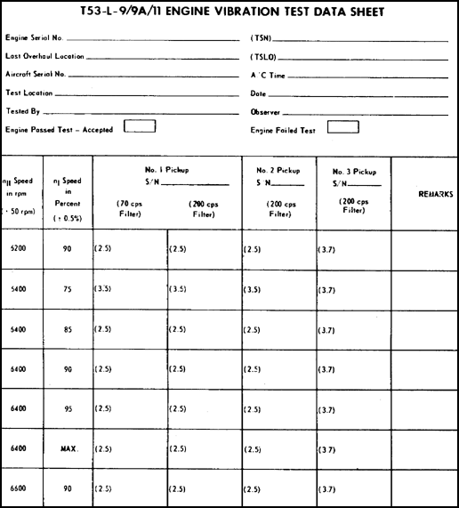
Figure 3.4. Engine Vibration Test Data Sheet.
3.4. JETCAL ANALYZER
To check the exhaust gas temperature (ECT) system when periodic maintenance inspections are required, or to troubleshoot the system if abnormally high or low temperatures are noted, the jetcal analyzer shown in figure 3.5 is used.
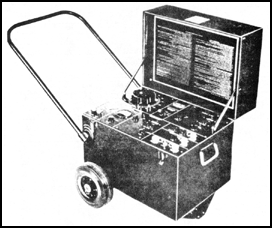
Figure 3.5. Jetcal Analyzer.
When checking the engine exhaust gas temperature (EGT)system, the jetcal is used to heat the thermocouple to the desired temperature without running the engine. The portable jetcal analyzer is equipped with a handle and two rubber wheels for easy movement. The jetcal operates on 95 to 135 volts, 50 to 400 cycles ac power supply.
3.5. SCHEDULED AND SPECIAL INSPECTIONS
Gas turbine engines are inspected at regular intervals -- scheduled. The inspection requirements are stated in a required order to assure that defects are discovered and corrected before malfunctioning or serious trouble results.
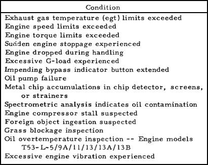
A special inspection is required whenever any of the operating limitations have been exceeded. Table II is a list of some of the conditions when a special inspection is required.
SPECIAL INSPECTION TABLE
3.6. ARMY SPECTROMETRIC OIL ANALYSIS PROGRAM (ASOAP)
In the ASOAP program samples of used oil containing microscopic metal particles are sent periodically to an oil analysis laboratory. There the oil and its metal particles are burned by an electric or gas flame. The wave length of the light emitted from the burning oil and metal particles is measured to determine the kind and quality of metal in the oil. The identification gives advance warning of excessive wear on particular engine parts, thereby aiding in preventing inflight engine failures.
3.7. ENGINE MAINTENANCE PRECAUTIONS
Personnel performing maintenance on gas turbine engines must observe the precautions stated in the applicable engine manual. Disregarding these warnings and precautionary measures can result in serious injury, illness, or death. The following subparagraphs discuss some of the precautions that must be taken while performing engine maintenance.
![]() a. Use of lubricating oil. Prolonged contact with lubricating oil may cause a skin rash. Skin and clothing that come in contact with lubricating oil must be thoroughly washed immediately. Saturated clothing should be removed without delay. Areas in which lubricating oil is used must be ventilated to keep mist and fumes to a minimum. Because lubricating oil can soften some paint, oil spilled on painted surfaces must be promptly and thoroughly washed off.
a. Use of lubricating oil. Prolonged contact with lubricating oil may cause a skin rash. Skin and clothing that come in contact with lubricating oil must be thoroughly washed immediately. Saturated clothing should be removed without delay. Areas in which lubricating oil is used must be ventilated to keep mist and fumes to a minimum. Because lubricating oil can soften some paint, oil spilled on painted surfaces must be promptly and thoroughly washed off.
![]() b. Cadmium plated tools. Be sure tools used on engine are not cadmium plated. The cadmium plating on tools chips off, and oil contaminated with cadmium chips can cause magnesium parts to deteriorate.
b. Cadmium plated tools. Be sure tools used on engine are not cadmium plated. The cadmium plating on tools chips off, and oil contaminated with cadmium chips can cause magnesium parts to deteriorate.
![]() c. Handling of parts. When handling combustion chamber internal parts that have been exposed to fuels containing tetraethyl lead compounds, be sure that the poisonous lead-oxide residue is not inhaled or taken into the body through cuts or other external openings. If accidental exposure occurs, flush the affected area thoroughly with clear water and obtain immediate medical attention. Gloves and a face mask should be worn at all times when handling parts contaminated by lead oxide. hi addition bearings must be handled with special care. Gloves must be worn to prevent skin oil and acid from etching the bearing surface.
c. Handling of parts. When handling combustion chamber internal parts that have been exposed to fuels containing tetraethyl lead compounds, be sure that the poisonous lead-oxide residue is not inhaled or taken into the body through cuts or other external openings. If accidental exposure occurs, flush the affected area thoroughly with clear water and obtain immediate medical attention. Gloves and a face mask should be worn at all times when handling parts contaminated by lead oxide. hi addition bearings must be handled with special care. Gloves must be worn to prevent skin oil and acid from etching the bearing surface.
![]() d. Marking on high-temperature materials. Using marking materials such as a common lead pencil on metals subject to high temperatures can cause the metal parts to crack. Approved marking materials are specified in the applicable engine manual. Only these marking materials are authorized for use.
d. Marking on high-temperature materials. Using marking materials such as a common lead pencil on metals subject to high temperatures can cause the metal parts to crack. Approved marking materials are specified in the applicable engine manual. Only these marking materials are authorized for use.
![]() e. Performing maintenance while engine is operating. Maintenance personnel must use caution when performing maintenance on operating engines. Because of the high temperature and velocity of the exhaust gases, personnel must stay clear of exhaust areas. Turbine intake areas are also a hazard. Large jet engines have been known to suck men into the engine. The smaller turbine engines in Army aircraft are capable of picking up small objects that are close to the intake. Anyone working around turbine engines should remove headgear and loose articles such as pens and pencils from shirt pockets. Figure 3.6 shows the exhaust-blast area of an OV-1 aircraft, to be avoided when the engine is running.
e. Performing maintenance while engine is operating. Maintenance personnel must use caution when performing maintenance on operating engines. Because of the high temperature and velocity of the exhaust gases, personnel must stay clear of exhaust areas. Turbine intake areas are also a hazard. Large jet engines have been known to suck men into the engine. The smaller turbine engines in Army aircraft are capable of picking up small objects that are close to the intake. Anyone working around turbine engines should remove headgear and loose articles such as pens and pencils from shirt pockets. Figure 3.6 shows the exhaust-blast area of an OV-1 aircraft, to be avoided when the engine is running.
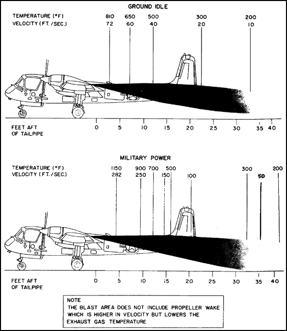
Figure 3.6. Exhaust - Blast Area.
3.8. MAINTENANCE PROCEDURES
It is important to see that the engine compartment is kept as clean as possible because the high-velocity airflow through the engine will draw any foreign objects into the compressor. All loose parts, such as safety wire, cotter pin clippings, and nuts and bolts should be removed immediately. Tubing and lines should be checked for security, nicks, chafing, dents, and leaks.
Inspection and maintenance of gas-turbine engines are somewhat easier than those of reciprocating engines because the gas turbines stay cleaner. Besides, the first several stages of most compressors can be inspected for FOD by using a strong light. Also, the last two turbine stages are readily opened for inspection of heat damage.
The oil system is checked on the daily inspection for proper oil level. However, when adding oil, different types should not be mixed. In the past the Army has used MIL-L-7808 lubricating oil in turbine engines. Because of the higher operating temperatures encountered in the current gas turbine engines, a new oil has been developed. Military Specification No. MIL-L-23699 uses a new synthetic base and new additive combination to cope with the more severe operating conditions and higher temperature ratings. When changing from MIL-L-7808 to MIL-L-23699 lubricating oil, check the engine TM for proper procedures.
3.9. CLEANING ENGINE ASSEMBLY
The exterior of the engine, and its attached components, can be cleaned with a suitable cleaning solvent, such as P-D-680. If the solvent is sprayed on the engine with compressed air, care must be taken to avoid forcing dirt, solvent, or moisture into engine openings and electrical connections. The primary purpose of cleaning is to remove contaminants that might conceal minor cracks and defects which if not detected could eventually lead to failure. Under normal circumstances, engine components are cleaned only as necessary to perform required inspection and repair. After using alternate or emergency fuels, cleaning internal hot-end parts may be required to remove lead oxide deposits. These deposits, if not removed, are detrimental to engine life and performance. The choice of any particular cleaning agent or process depends upon the engine part to be cleaned and the contaminants to be removed.
Take particular care in selecting a cleaning method to ensure that anodizing or dichromating is not removed from the surfaces. Do not use caustics on aluminum, magnesium, ceramic-coated, aluminized, painted, nitrated, or carbonized parts. In most cases the engine manual prescribes the approved cleaning procedure to be used. Most engine parts may be cleaned by using the following methods.
![]() a. Vapor degreasing. Used only on unpainted metal parts or aluminum-painted steel parts, vapor degreasing using heated trichloroethylene, type II, or perchloroethylene, specification No. O-T-634, removes oil, grease, and sludge. The hot vapor condenses on metal surfaces, liquefies, and carries away the oil, grease, and sludge. Parts may be flushed while held in the vapor. To prevent corrosion, the parts should not be removed from solvent vapors until they have reached the temperature of the vapor.
a. Vapor degreasing. Used only on unpainted metal parts or aluminum-painted steel parts, vapor degreasing using heated trichloroethylene, type II, or perchloroethylene, specification No. O-T-634, removes oil, grease, and sludge. The hot vapor condenses on metal surfaces, liquefies, and carries away the oil, grease, and sludge. Parts may be flushed while held in the vapor. To prevent corrosion, the parts should not be removed from solvent vapors until they have reached the temperature of the vapor.
![]() b. Solvent immersion. In another cleaning method, the parts are immersed in Carbon Removing Compound MIL-C-19853, to remove carbon, gum, grease, and other surface contaminants. This method is used on steel and stainless steel parts. Parts with painted finishes should not be cleaned by this method, because the carbon cleaning compound attacks the paint.
b. Solvent immersion. In another cleaning method, the parts are immersed in Carbon Removing Compound MIL-C-19853, to remove carbon, gum, grease, and other surface contaminants. This method is used on steel and stainless steel parts. Parts with painted finishes should not be cleaned by this method, because the carbon cleaning compound attacks the paint.
![]() c. Vapor blasting. An abrasive method used to clean combustor parts, vapor blasting must not be used on ceramic, magnesium, painted, or aluminum surfaces. Be sure that metal is not removed during cleaning and that cooling slots, holes, ridges, and overlap areas do not become clogged with blasting grit.
c. Vapor blasting. An abrasive method used to clean combustor parts, vapor blasting must not be used on ceramic, magnesium, painted, or aluminum surfaces. Be sure that metal is not removed during cleaning and that cooling slots, holes, ridges, and overlap areas do not become clogged with blasting grit.
![]() d. Dry-cleaning solvent. All metal parts may be cleaned with dry-cleaning solvent, P-D-680 Type I. This method is suitable for removing heavy oil and grease deposits from most parts, including flexible hoses and carbon seals. Dry-cleaning solvent leaves an oily film that protects steel parts from corrosion for a short time.
d. Dry-cleaning solvent. All metal parts may be cleaned with dry-cleaning solvent, P-D-680 Type I. This method is suitable for removing heavy oil and grease deposits from most parts, including flexible hoses and carbon seals. Dry-cleaning solvent leaves an oily film that protects steel parts from corrosion for a short time.
3.10. CLEANING COMPRESSOR ROTOR BLADES
When a particular engine's performance decreases to or below the point specified in the applicable TM, and the EGT increases steadily during normal operation, the compressor rotor blades need cleaning. Compressor rotor blades should also be cleaned whenever the engine has been operating in areas where the air is salt laden, or when the engine has been subjected to contamination with fire extinguishing agent residue (chlorobromomethane and soda ash). Cleaning can be accomplished while the engine is installed in the aircraft.
Before cleaning any engine the applicable engine technical manual must be consulted for the proper procedures to follow. On some engines, temperature and pressure lines must be disconnected and capped to prevent solvent and water from entering.
The following is the preferred method for cleaning the compressor on the T53-L-13. Refer to figure 3.7 as you read the following steps in the cleaning method.
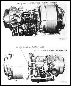
Figure 3.7. Compressor Blade Cleaning.
![]() a. Remove airframe air intake components as necessary.
a. Remove airframe air intake components as necessary.
![]() b. Remove the inlet air-temperature sensing element from the inlet housing.
b. Remove the inlet air-temperature sensing element from the inlet housing.
![]() c. Disconnect the pressure line to bleed band actuator and cap the diffuser fitting with AN929-6 cap assembly.
c. Disconnect the pressure line to bleed band actuator and cap the diffuser fitting with AN929-6 cap assembly.
![]() d. Block off the customer bleed air supply at the customer airbleed port in the airbleed adapter assembly.
d. Block off the customer bleed air supply at the customer airbleed port in the airbleed adapter assembly.
![]() e. While the engine is cold, rotate it with the starter and spray one quart of dry-cleaning solvent (P-D-680 Type 1) evenly through all sections of the inlet housing. Make sure both sides of the inlet guide vanes are covered with solvent.
e. While the engine is cold, rotate it with the starter and spray one quart of dry-cleaning solvent (P-D-680 Type 1) evenly through all sections of the inlet housing. Make sure both sides of the inlet guide vanes are covered with solvent.
![]() f. Stop motoring the engine and let it stand for at least one hour to permit the dry cleaning solvent to loosen dirt.
f. Stop motoring the engine and let it stand for at least one hour to permit the dry cleaning solvent to loosen dirt.
![]() g. Clean the inlet guide vanes with a small, round fiber brush with a long handle.
g. Clean the inlet guide vanes with a small, round fiber brush with a long handle.
![]() h. Start the engine and operate it at flight idle.
h. Start the engine and operate it at flight idle.
![]() i. Spray CLEAN fresh water evenly into all sections of the inlet housing at the rate of two gallons per minute for approximately two minutes. To avoid freezing at ambient temperatures below 35° F (1.5° C), use anti-detonating injection fluid or a mixture containing 40 percent methanol and 60 percent water in lieu of water.
i. Spray CLEAN fresh water evenly into all sections of the inlet housing at the rate of two gallons per minute for approximately two minutes. To avoid freezing at ambient temperatures below 35° F (1.5° C), use anti-detonating injection fluid or a mixture containing 40 percent methanol and 60 percent water in lieu of water.
![]() j. Allow the engine to run for 2 to 5 minutes to dry out; then shut the engine down.
j. Allow the engine to run for 2 to 5 minutes to dry out; then shut the engine down.
![]() k. Inspect the inlet guide vanes and compressor for cleanliness.
k. Inspect the inlet guide vanes and compressor for cleanliness.
![]() l. Repeat the cleaning procedure if necessary.
l. Repeat the cleaning procedure if necessary.
![]() m. Reconnect the lines for normal operation.
m. Reconnect the lines for normal operation.
![]() n. Clean the temperature sensing element with dry-cleaning solvent and reinstall it.
n. Clean the temperature sensing element with dry-cleaning solvent and reinstall it.
3.11. OVERHAUL AND REPAIR
The time between overhauls (TBO) varies considerably between different engines. The TBO is established by the Army and the engine manufacturer who take into account the kind of operation and use expected for the engine, also the environment it will be operating in. As a specific model engine builds up operating time, it is inspected for signs of wear and impending failure of parts. If the engine is wearing well, the TBO is extended. The large improvement of TBO has been accomplished mainly through improvements in engine design, metallurgy, manufacturing, overhaul, inspection, and maintenance procedures. The use to which the engine is put is especially important in determining the TBO. For example, if the mission the aircraft is designed for calls for frequent starts and stops, or for power changes as in a helicopter, the resultant rapid temperature changes will shorten the allowed TBO. The following paragraphs cover disassembly, assembly, and repair procedures.
![]() a. Disassembly. Engine disassembly can be accomplished on a vertical or horizontal disassembly stand as shown in figure 3.8. Some engines can be disassembled either horizontally or vertically, while others have to be done in only one position. After the engine is disassembled, the major components and section assembly are mounted on individual stands. To disassemble an engine, instructions in the TM must be followed, and a large number of special tools is required. A set of these tools may cost as much as the engine.
a. Disassembly. Engine disassembly can be accomplished on a vertical or horizontal disassembly stand as shown in figure 3.8. Some engines can be disassembled either horizontally or vertically, while others have to be done in only one position. After the engine is disassembled, the major components and section assembly are mounted on individual stands. To disassemble an engine, instructions in the TM must be followed, and a large number of special tools is required. A set of these tools may cost as much as the engine.
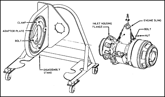
Figure 3.8. Engine Disassembly Stand.
![]() b. Assembly. Engine assembly also follows instruction in the TM; it is done on the same stand as disassembly. During assembly, care must be taken to prevent dirt and other foreign materials from entering the engine. The procedures and use of special tools as outlined in the maintenance manual must be followed to minimize possible injury to the mechanic and damage to the engine.
b. Assembly. Engine assembly also follows instruction in the TM; it is done on the same stand as disassembly. During assembly, care must be taken to prevent dirt and other foreign materials from entering the engine. The procedures and use of special tools as outlined in the maintenance manual must be followed to minimize possible injury to the mechanic and damage to the engine.
![]() c. Repair. All engine parts must be repaired using methods approved by the engine TM. Figure 3.9 shows an illustration of typical repair limits for compressor rotor blades on the Lycoming T53 series engines.
c. Repair. All engine parts must be repaired using methods approved by the engine TM. Figure 3.9 shows an illustration of typical repair limits for compressor rotor blades on the Lycoming T53 series engines.
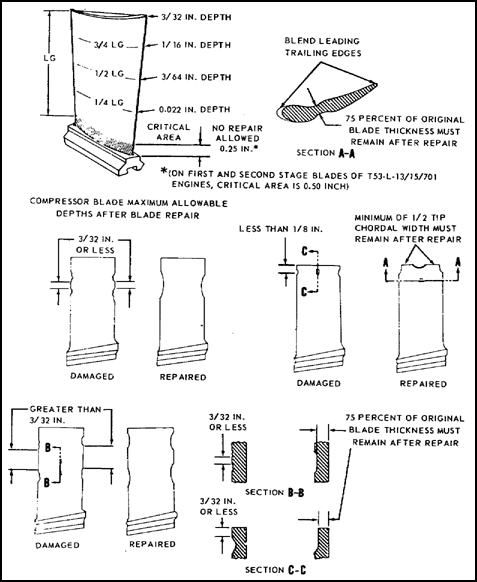
Figure 3.9. Compressor Rotor Blade Damage Before and After Repair.
3.12. MAINTENANCE ALLOCATION CHART
Maintenance function assignments are determined by the maintenance allocation chart found in the aircraft -20 technical manual. The maintenance allocation chart assigns functions to the lowest capable maintenance level based on past experience, and the skills, tools, and time available. Maintenance that cannot be performed at the assigned level may be reassigned to the next higher level. Generally, there is no deviation from the assigned level of maintenance. However, in cases of operational necessity, higher level function is assigned to a lower level by the maintenance officer of the level to which the function is originally assigned. Figure 3.10 shows an example of a maintenance allocation chart for UH-1D and H series helicopters. The symbols "O, F, H and D" represent: organizational maintenance (O), direct support maintenance (F), general support maintenance (H), and depot maintenance (D). When one of these symbols is placed on the allocation chart, it indicates the lowest level of maintenance responsible for performing the particular maintenance function. Maintenance levels higher than the level symbolized on the chart are authorized to perform the indicated maintenance.

Figure 3.10. Maintenance Allocation Chart.
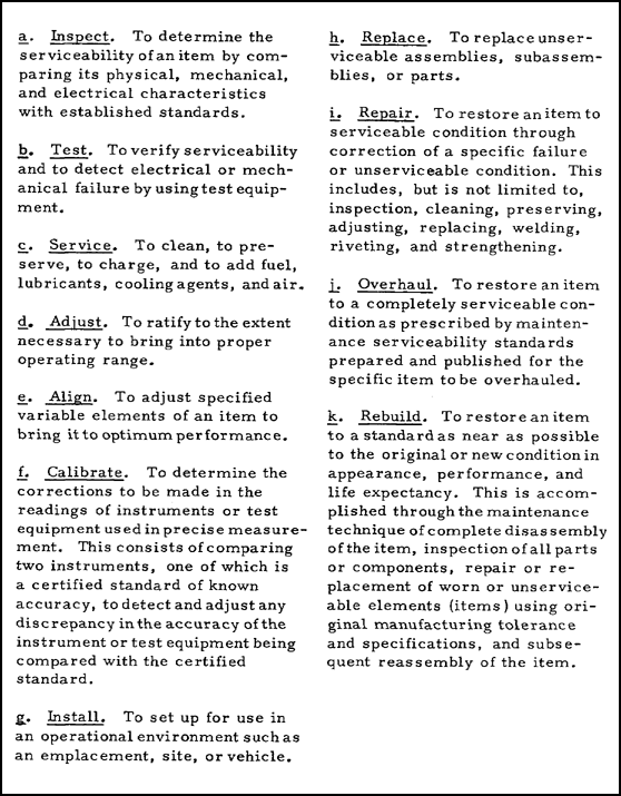
The terms used in block (3) of the maintenance allocation chart are explained in table III for convenience in reviewing and for future reference.
3.13. STORAGE AND PRESERVATION
The degree of preservation is determined by the anticipated length of time an engine is expected to be inactive. The three categories of storage are:
![]() a. Flyable storage. An engine that will not be operated for a period of at least 72 hours, nor more than 14 days, must be preserved and maintained with all components and systems in an operable condition. On the third day, the engine must be run-up or motored with the starter. If the engine is only motored on the third day, it must be run up on the seventh.
a. Flyable storage. An engine that will not be operated for a period of at least 72 hours, nor more than 14 days, must be preserved and maintained with all components and systems in an operable condition. On the third day, the engine must be run-up or motored with the starter. If the engine is only motored on the third day, it must be run up on the seventh.
TABLE III
DEFINITIONS OF MAINTENANCE TERMS
![]() b. Temporary storage. An engine that will not be operated for over 14 days, but less than 45 days, must be placed in temporary storage. Engines normally falling in this category are those undergoing minor repair or modification, awaiting assignment or disposition, being held in operational reserve, or any other condition which requires idleness for a period not to exceed 45 days.
b. Temporary storage. An engine that will not be operated for over 14 days, but less than 45 days, must be placed in temporary storage. Engines normally falling in this category are those undergoing minor repair or modification, awaiting assignment or disposition, being held in operational reserve, or any other condition which requires idleness for a period not to exceed 45 days.
![]() c. Extended storage. An engine that will be inactive for more than 45 days, but not exceeding 180 days, must be preserved and maintained in extended storage. Usually, this includes those engines undergoing major repair or modification, those declared surplus and awaiting final disposition, or any other circumstance that would warrant idleness for 45 to 180 days.
c. Extended storage. An engine that will be inactive for more than 45 days, but not exceeding 180 days, must be preserved and maintained in extended storage. Usually, this includes those engines undergoing major repair or modification, those declared surplus and awaiting final disposition, or any other circumstance that would warrant idleness for 45 to 180 days.
NOTE
Permanent storage is a depot level function.
ENGINE PRESERVATION - GENERAL. All preservation procedures require that any accumulation of dirt be removed from the engine with dry cleaning solvent. Under usual conditions, it will not be necessary to clean the entire external surface of the engine. If necessary, perspiration residues can be removed from close tolerance bare metal surfaces by wiping with a clean cloth dampened in fingerprint remover before cleaning with solvent.
CAUTION
To prevent oil contamination, never mix synthetic-base oils with mineral-base oils. Synthetic-base lubricating oil is required for the engine. Only a synthetic-base corrosion preventive oil can be used to spray the compressor for corrosion prevention.
3.14. TURBINE ENGINE TROUBLESHOOTING
Engine malfunctions can be recognized and diagnosed by comparing actual engine instrument reading with normal readings. To aid maintenance personnel in engine troubleshooting, the engine technical manual has troubleshooting charts to analyze, isolate, and correct engine malfunctions. Proper utilization of the troubleshooting charts will save time, provide a logical method of isolating the causes of malfunctions, and eliminate the unnecessary replacement of parts. Figure 3.11 explains how to use the troubleshooting charts.
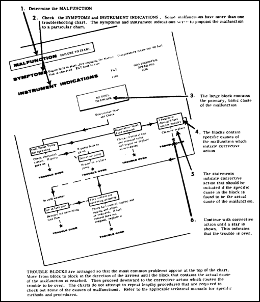
Figure 3.11. How to Use Troubleshooting Charts.
3.15. SUMMARY
Gas turbine engines are run in test cells to ensure quality control before they are shipped to the user for installation in aircraft. The test cell is equipped with instruments to monitor engine performance. Engine vibration tests can be performed with the engine in the test cell or installed in the aircraft. Vibration tests are required after any maintenance on rotating parts or when excessive engine vibration is suspected. A jetcal analyzer is used to check the accuracy of the egt system and to calibrate it.
There are two kinds of engine inspections, scheduled and special. Scheduled inspections are required whenever any of the operating limits have been exceeded.
Under the Army Spectrometric Oil Analysis Program (ASOAP) oil samples are analyzed for metal content, to prevent in-flight engine failures.
Personnel performing maintenance on gas turbine engines should observe the precautions stated in the engine manual to avoid serious personnel injury or engine damage. All engine cleaning, both internal and external, should be performed in accordance with the appropriate engine manual. In most cases the engine manual prescribes the approved cleaning procedure to be used. Most engine parts may be cleaned by the vapor degreasing, solvent immersion, or vapor blasting methods.
The TBO of a gas turbine engine depends upon such things as operating environment, mission to be performed, and how will the engine wear as flight time is built up.
Maintenance function assignments are determined by the maintenance allocation chart found in the aircraft -20 manual. Three categories of engine storage are used. The decision as to which category of storage is to be used depends upon the length of time the engine will be inactive.
GO TO:

