


EA-1049; Environmental Assessent and FONSI Proposed Replacement and Operation of the Athyrous Hydrogen Fluoride Supply and Fluidized-bed Chemical Processing Systems at Building 9212 September 1995
TABLE OF CONTENTS
2. PROPOSED ACTION AND ALTERNATIVES
-
2.1 PROPOSED ACTION-REPLACEMENT OF THE AHF SUPPLY AND FLUIDIZED-BED REACTOR SYSTEMS
2.1.1 Construction
2.1.2 Operation
2.1.3 Emissions, Effluents, Wastes
2.2 NO-ACTION ALTERNATIVE
2.3 EXTENSIVE MODIFICATIONS OF CURRENT AHF SUPPLY AND FLUIDIZED-BED REACTOR SYSTEMS
2.4 TERMINATION AND SHUTDOWN OF AHF SUPPLY AND FLUIDIZED-BED REACTOR SYSTEMS
2.5 USE OF OTHER DOE OR NON-DOE FACILITIES
2.6 ALTERNATIVE TECHNOLOGIES
2.7 ALTERNATIVE SITES AT THE Y-12 PLANT
-
3.1 AIR QUALITY
3.2 WATER RESOURCES
3.3 SOIL
3.4 ARCHAEOLOGICAL AND CULTURAL RESOURCES
3.5 BACKGROUND RADIATION
-
4.1 DEMOLITION AND CONSTRUCTION
4.1.1 Air Quality
4.1.2 Soils/Topography
4.1.3 Water Quality
4.1.4 Natural and Historic Resources 4.1.5 Health and Safety
4.1.6 Waste Management
4.2 IMPACTS OF INCIDENT-FREE OPERATION
4.2.1 Air Quality
4.2.2 Health and Safety
4.2.3 Waste Management
4.3 IMPACTS OF ACCIDENTS
4.3.1 Hazardous Materials
4.3.2 Accident Identification
4.3.3 Accident Analysis
4.4 ENVIRONMENTAL JUSTICE
4.5 NO-ACTION ALTERNATIVE
4.6 CUMULATIVE IMPACTS
5. PERMITS AND REGULATORY REQUIREMENTS
-
5.1 CLEAN AIR ACT
5.2 FEDERAL WATER POLLUTION CONTROL ACT
5.3 ENDANGERED SPECIES ACT
5.4 NATIONAL HISTORIC PRESERVATION ACT
5.5 OCCUPATIONAL SAFETY AND HEALTH ADMINISTRATION
5.6 EMERGENCY PLANNING AND COMMUNITY RIGHT-TO-KNOW ACT AND EXECUTIVE ORDER 12856
5.7 TOXIC SUBSTANCES CONTROL ACT
6. RELATIONSHIP WITH APPLICABLE LAND USE PLANS
7. DOE DECISION PROCESS ON RELATED ACTIONS
APPENDIX A
FONSI
LIST OF FIGURES
1.1. Map showing the location of Oak Ridge and the Oak Ridge Reservation in relation to the geographic region
1.2. Map showing DOE's Oak Ridge Reservation and the location of the three major installations
1.3. Y-12 Plant location site plan, highlighting the site of the proposed action
2.1. Dock 8/8A site utility plan
2.2. Proposed AHF supply and distribution system equipment layout
2.3. Glovebox systems for transfer of uranium trioxide
2.4. AHF supply and fluidized-bed reactor systems process block flow diagram
4.1 City of Oak Ridge, census tracts 1990
LIST OF TABLES
Table 2.1. Comparison of existing and proposed replacement hydrogen fluoride supply systems
Table 2.2. Proposed construction schedule for the AHF supply system and fluidized-bed reactor systems
Table 4.1. Protective equipment requirements for demolition work
Table 4.2. Accident scenarios and potential impacts
Table 4.3. 1990 population distribution by race in census tracts near the Y-12 Plant
Table 4.4. 1989 household income by census tract
Table 4.5. 1994 Federal Poverty Guideline on income levels by size of family unit for all states
ACRONYMS AND ABBREVIATIONS
- AHF
- anhydrous hydrogen fluoride
- CFR
- Code of Federal Regulations
- DOE
- U.S. Department of Energy
- EA
- Environmental Assessment
- EIS
- environmental impact statement
- Energy Systems
- Lockheed Martin Energy Systems, Inc.
- ERPGs
- Emergency Response Planning Guides
- HF
- hydrogen fluoride
- NDA
- non-destructive analysis
- NPDES
- National Pollutant Discharge Elimination System
- PCB
- polychlorinated biphenyl
- PEIS
- programmatic environmental impact statement
- PHA
- preliminary hazards analysis
- SAIC
- Science Applications International Corporation
GLOSSARY
Anhydrous hydrogen fluoride (AHF): A chemical form of hydrogen fluoride in which water is essentially absent. AHF has a purity of 99 to 99.9 percent. Hydrogen fluoride containing water molecules (designated as HF in this document) is generally produced commercially as a 70 percent solution. Both forms of the compound (AHF and HF) occur at various stages of the process described in this document.
B-25 containers: Metal waste storage containers with approximate dimensions of 1.2 m X 1.8 m X 1.2 m (4 ft X 6 ft X 4 ft) and volumes of 2.6 m3 (96 ft3).
Design-basis accident: An accident scenario that provides the basis for the design of preventative or mitigative features. For this proposed action, it is assumed to be the loss of 363 kg (800 lbs) of liquid AHF per hour within the sealed cylinder enclosure at Dock 8/8A coupled with the absence of a functioning stack scrubber.
Dip tube:A tube at or near the bottom of an AHF cylinder that evacuates AHF as nitrogen gas is added to the AHF cylinder. The increased pressure in the cylinder that results from adding nitrogen gas forces the AHF into the dip tube and, subsequently, into the AHF delivery system for use at the hydrofluorination fluidized-bed reactor.
Existing System:Original system including all upgrades to improve safety and operations as implemented through 1994.
Fluidized-bed reactor:As referred to in this document, a fluidized-bed reactor is a cylindrical structure, approximately 15 cm (6 in.) in diameter, that would initially contain either uranium trioxide powder or uranium dioxide powder. The cylinder would be heated and nitrogen gas introduced to suspend the uranium powder within the cylinder. The suspended powder would resemble a boiling liquid. After the appropriate reaction temperature was reached, the nitrogen gas would be replaced by either hydrogen gas (in the case of uranium trioxide) or AHF gas (in the case of uranium dioxide). The reaction would be allowed to proceed to the completion products of uranium dioxide or uranium tetrafluoride, respectively.
Fugitive emissions:Uncontrolled air emissions that escape from the operating system and are not treated prior to discharge.
High-level switch:A detection system that shuts down the AHF transfer process when the AHF liquid level reaches a predetermined point.
Highly enriched uranium metal:Metal consisting of purified uranium with an enrichment of the uranium-235 isotope in excess of 20 percent by weight.
Hydrostatically tested: Equipment is filled with liquid under pressure to ensure that no leaks are present at the prescribed operating pressure. Equipment is usually tested at pressures above normal operating pressures.
Material access area: A controlled security area that segregates highly enriched uranium storage areas from normal industrial operations.
Mixed waste: Waste that contains both radioactive and hazardous components.
Monel metal: Used for an alloy of approximately 67 percent nickel, 28 percent copper, and 5 percent other elements that is made by direct reduction from ore in which the constituent metals occur in these proportions.
Nuclear criticality:The attainment of physical conditions such that a fissile material will sustain a chain reaction.
Nuclear-safe geometry:A geometric configuration that prevents a fissile material from becoming critical by keeping the surface-to-volume ratio such that excessive neutron leakage makes it impossible to attain criticality.
100-year floodplain:A flat or nearly flat land surface that has a 1 percent chance of being flooded in any given year.
Order of magnitude:A range of magnitude extending from some value to ten times that value. Two quantities are of the same order of magnitude if one is no larger than ten times the other; but if one is one hundred times the other, it is larger by two orders of magnitude.
Pigtail:Flexible tubing that allows ease of connection to a rigid piping system. Pigtail refers to its corkscrew or pigtail appearance.
Pneumatically operated or transferred: Filled with or operated by compressed gas.
Radionuclide:A radioactive species of an atom that gives off, or is capable of giving off, radiant energy in the form of particles (alpha or beta radiation) or rays (gamma radiation) by the spontaneous disintegration of the nuclei of atoms. Radioisotopes of elements lose particles and energy through the process of radioactive decay. Elements may decay into a different atom(s) or a different state of the same atom.
Scrubber: An air pollution control device that uses either a spray of water or reactant or a dry process to physically trap and/or chemically alter potential air pollutants found in the exhaust air stream prior to their atmospheric release.
Venturi scrubber:As referred to in this document, a Venturi scrubber is a high-efficiency scrubber that uses a pressure differential to drive a chemical reaction between AHF and either water or potassium hydroxide to neutralize the AHF.
Waste stream:The waste products that result from an industrial process or other waste-producing activity. A waste stream can refer to the generation of one particular waste or many.
EXECUTIVE SUMMARY
The U.S. Department of Energy (DOE) proposes to replace the existing anhydrous hydrogen fluoride (AHF) supply and fluidized-bed reactor systems for the Weapons Grade Highly Enriched Uranium Chemical Recovery and Recycle Facility, Building 9212, which is located within the Y-12 Plant on DOE's Oak Ridge Reservation in Oak Ridge, Tennessee.
The current AHF supply and fluidized-bed reactor systems were designed and constructed more than 40 years ago. Because the corrosive nature of the processed materials has led to continuously deteriorating conditions, the long-term reliability of the system cannot be assured. The current AHF supply system cannot completely mitigate an accidental release of AHF and vents fugitive AHF directly to the atmosphere during operations. The proposed action would reduce the risk of exposing the Y-12 Plant work force, the public, and the environment to an accidental release of AHF and would ensure the continuing ability of the Y-12 Plant to manufacture highly enriched uranium metal and process uranium from retired weapons for storage.
The proposed replacement system would be based upon modern design criteria and safety analyses. The replacement AHF supply and distribution system equipment would be located on the existing Dock 8/8A at Building 9212. Utilities would be extended to the dock to service the process equipment. The following process equipment modules would be prefabricated for installation at the modified dock: an AHF cylinder enclosure, an AHF supply manifold and vaporizer module, an AHF sump tank and transfer skid, and an AHF supply off-gas scrubber assembly module.
The fluidized-bed reactor system would be constructed in an area adjacent to the existing system in Building 9212. The replacement equipment would consist of a new reduction fluidized-bed reactor, a hydrofluorination fluidized-bed reactor, and associated air emission control equipment. The no-action alternative, which is the continued operation of the existing AHF supply and fluidized-bed reactor systems, was also evaluated. Three other alternatives were considered and evaluated but dismissed from further consideration: (1) extensive modification of the existing systems, which was dismissed because it was not practical or cost effective; (2) shutdown of the systems and termination of the activities they support, which was not considered further because it would prevent DOE from fulfilling its mission; and (3) alternative technologies, which were dismissed because they are unproven at the production scale. The findings of this Environmental Assessment are as follows:
- Air quality would be improved because 99.9 percent of fugitive emissions
from the proposed AHF supply system would be removed by scrubbers.
- Water resources would not be affected because no new effluents would be produced.
- Soil disturbance related to construction would be minimal and only
subsurface soil would be disturbed.
- No natural habitat would be disturbed and no threatened or endangered
species would be affected.
- No wetlands or floodplains would be altered or impacted by the proposed
action.
- Although modifications would be made to Building 9212, which may be
designated as historically significant, the modifications would not change the
use of the building.
- No minority or low-income populations would be adversely affected by the
proposed action.
- The replacement systems would lessen the risk of an AHF exposure to the
worker population and the general public. The control systems would prevent
uncontrolled AHF emissions, eliminating any potential threat to the general
public and worker population in the vicinity. In the event of an accident, the
new equipment would capture the entire inventory of AHF in the secondary
containment enclosure.
- The design basis accident [release of 363 kg (800 lb) liquid AHF in the cylinder enclosure per hour coupled with no functional stack scrubber] would produce no serious or irreversible health effects.
1. INTRODUCTION
1.1 PURPOSE AND NEED FOR ACTION
The U.S. Department of Energy (DOE) proposes to replace the existing anhydrous hydrogen fluoride (AHF) supply and fluidized-bed reactor* systems for the Weapons Grade Highly Enriched Uranium Chemical Recovery and Recycle Facility, Building 9212, which is located within the Y-12 Plant on DOE's Oak Ridge Reservation in Oak Ridge, Tennessee.
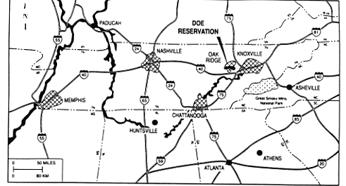
Manufacture, chemical recovery, and recycling of highly enriched uranium are unique capabilities of the Oak Ridge Y-12 Plant, which is managed for DOE by Lockheed Martin Energy Systems, Inc. (Energy Systems) (Fig. 1.1). The capabilities for manufacture and chemical recovery and recycling of highly enriched uranium are necessary to fulfill several DOE missions: (1) converting uranium-containing salvage materials to alternate forms more readily accountable and suitable for storage, (2) providing safe and accountable storage of highly enriched uranium at a national repository where prestorage processing is available to support continued weapons dismantlement, and (3) maintaining nuclear competence and providing requested specification-grade highly enriched uranium for weapons component fabrication and for other DOE customers (DOE 1994b).
Fig. 1.2. Map showing DOE's Oak Ridge Reservation and the location of the three major installations.
An AHF supply and fluidized-bed reactor system is required for the manufacture and chemical recovery and recycling of purified highly enriched uranium metal.* These systems convert uranium trioxide (UO3) to uranium tetrafluoride (UF4) which is an integral part of the uranium metal recycling process. To meet DOE mission requirements, these systems effective operating life must be extended 25 years. For long-term viability, these systems must meet applicable federal environmental requirements and industrial guidelines for the handling and use of hazardous materials, which include Code of Federal Regulations(CFR) 29 CFR1910.119 Process Safety Management of Highly Hazardous Chemicals and Emergency Response Planning Guides (ERPG) for hydrogen fluoride (HF) developed as industrial standards by the American Industrial Hygiene Association; and all applicable DOE Orders including DOE 6430.1A General Design Criteria and DOE-STD-1020 Natural Phenomena Hazard Design and Evaluation Criteria for Department of Energy Facilities.
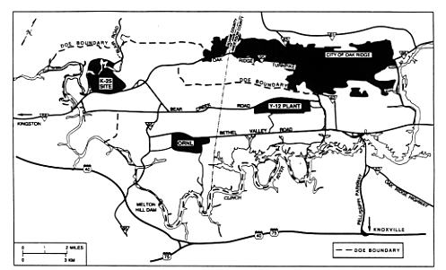
Presently, AHF storage vessels and equipment are located on the northeastern side of the Weapons Grade Highly Enriched Uranium Chemical Recovery and Recycle Facility, Building 9212, and the fluidized-bed reactors are located in the B-1 Wing of Building 9212 (Figs. 1.2and 1.3). The systems were designed and constructed more than 40 years ago, and their long-term reliability cannot be assured. The present AHF supply system and fluidized-bed reactors do not capture accidental releases of AHF; fugitive gases are vented directly to the atmosphere. Under incident-free operation, fugitive emissions* do not exceed limits established by the State of Tennessee (Energy Systems 1994).
Fig. 1.3. Y-12 Plant location site plan, highlighting the site of the proposed action.
The current AHF supply and fluidized-bed reactor system require a high degree of manual operation, which increases the potential for operator error and worker exposure. In January 1992, several factorsÄincluding an improperly set valve, which resulted in the activation of a relief valveÄresulted in an accidental release of AHF. The AHF release had a negligible environmental impact. The time of day, cold air temperature, stable atmospheric conditions, and wind direction during the release, all moderated the severity of the impacts. Seventeen on-site employees were affected by the HF vapor. All symptoms cleared up promptly, although two people lost 1 day away from work. Property damage included damage to glass and paint on several government-owned and privately-owned vehicles that were near the release location. A report on the investigation (Energy Systems 1992b) concluded, in addition to improvements in procedural, management, and conduct of operations systems, that modifications to the design and construction of the AHF supply system were needed to reduce the potential for a large release and to provide for isolation in the event of all releases.
As part of a strategic plan to restart the existing system,* which includes incorporating the recommendations of the investigation report, the following modifications were pursued within established government funding guidelines:
- 1992 Modifications: Completion of an ongoing (at the time of the accident) capital equipment project to replace the system's equipment. Total project funding was $950,000.
- 1994 Modifications: Fund two capital projects (1) HF Deluge System, and (2) HF Refrigeration System. Total funding for the two projects was $1,300,000. These interim measures were designed to minimize and mitigate the impacts of a small-quantity release of AHF (Energy Systems 1993a). However, design-basis accidental releases cannot be totally mitigated by these interim modifications.
- Request a Fiscal Year 1994 Congressional Line Item Project to replace the entire supply system providing capture, containment, and treatment of all potential releases (the proposed action).
In addition, long-term reliability of the existing system with completed interim modifications (beyond 5 years) cannot be assured. Thus, DOE has proposed this action.
1.2 BACKGROUND
The Y-12 Plant uses AHF as a vital raw material in its uranium salvage and recycle operations. AHF is necessary for the conversion of uranium dioxide to uranium tetrafluoride, which is a step in the production of enriched uranium metal (Energy Systems 1993c). AHF is the only proven production-scale chemical that can be used to convert uranium dioxide to the uranium tetrafluoride (Niemann 1992).
Highly enriched uranium metal is produced by a manufacturing process that begins with the thermal decomposition of uranyl nitrate solutions into uranium trioxide. The uranium trioxide is subsequently reduced with hydrogen to form uranium dioxide, which can then be converted to uranium tetrafluoride by reaction with AHF. A series of fluidized-bed reactors is used to accomplish these chemical conversions. The uranium tetrafluoride is reduced with calcium to generate highly enriched uranium metal. The reactant gases (hydrogen and AHF) used in the synthesis of oxides and fluorides of uranium are extremely hazardous materials that require exact design features and rigorous operating protocols for their safe use (Energy Systems 1993c). The proposed action does not involve any changes in the hydrogen supply system.
AHF exists either as a clear liquid or as a colorless gas that reacts with moisture in the air to produce a white fume. Either form is highly toxic to aquatic and terrestrial life. AHF is one of the most acidic substances known (Stecher 1968) and does not biodegrade when released in water, in air, or on land. It must be reacted, buffered, or diluted to reduce its acidity (EPA 1992). In most cases, because it is extremely reactive, AHF will be quickly neutralized by reaction with other substances upon release.
An air concentration of 30 parts per million AHF can be immediately dangerous to life and health (NIOSH 1990). In lower air concentrations, AHF can severely irritate the eyes, skin, and respiratory system (EPA 1992). The Occupational Safety and Health Administration limits occupational HF exposure to an 8-hour time-weighted average of 3 parts per million, which cannot be exceeded in an 8-hour work day. Burns resulting from exposure to less than 30 percent HF may not be painful or visible for several hours after exposure (Stecher 1968, EPA 1992). AHF has a low normal boiling point [19.5· C (67· F)] and a vapor density greater than air. Because of the high vapor pressure of AHF, even a small spill may present a severe health threat. For these reasons, extreme caution must be exercised in the transportation, storage, and processing of AHF (Energy Systems 1993c).
AHF is received at the Y-12 Plant in vendor-provided 590-kg (1,300-lb) capacity cylinders. The AHF cylinders are delivered by truck from the vendor to the loading and vaporization dock (Dock 8/8A) at Building 9212, where the AHF delivery system is operated. The cylinders are unloaded by a forklift equipped with a cylinder gripper, placed in a cradle that moves the cylinder into a refrigerated enclosure, and within the enclosure the cylinder valves are connected to the AHF delivery system. Nitrogen gas is then used to push the AHF liquid from the cylinders into a hot-water-jacketed vaporizer where the AHF is converted from a liquid to a gas. Once vaporized, the gaseous AHF is delivered to the fluidized-bed reactors, which require approximately 13.6 kg/hour (30 lb/hour) of AHF, delivered at 11.3 kg/6.5 cm2 (25 lb/in.2) gauge pressure and 93·C (200· F). The valving process is complicated; therefore, there is a potential for operator error (DOE 1991).
1.3 SCOPE OF THE ENVIRONMENTAL ASSESSMENT
The proposed action, described in Sect. 2.1, would be carried out at a previously disturbed industrial site, and all construction would be performed according to best management practices for soil erosion control. For this reason, construction would not adversely affect water resources and ecological resources. Baseline air quality is discussed in this Environmental Assessment (EA) to serve as a measure of improvements expected to result from operation of the new system. Socioeconomics is not evaluated because the existing labor pool would be used, and there would be no effects on demography, housing, schools, and other public services. Geologic features would not be altered because no large-scale excavation or topographic alteration would be needed. The focus of this EA is health and safety issues relevant to the proposed action and the no action alternative.
2. PROPOSED ACTION AND ALTERNATIVES
2.1 PROPOSED ACTION-REPLACEMENT OF THE AHF SUPPLY AND FLUIDIZED-BED REACTOR SYSTEMS
To reduce the probability of accidental releases that would expose the Y-12 Plant work force, the public, and the environment to AHF and to ensure that the ability of the Y-12 Plant to manufacture highly enriched uranium metal is maintained (Energy Systems 1993a), DOE has proposed replacement of the current AHF supply and fluidized-bed reactor systems. The current systems would remain in operation until the new systems are operational.
The proposed construction and operation of the replacement systems would provide an AHF supply and distribution system that would meet operational and safety requirements into the next century. The proposed AHF supply equipment would have an automated valve configuration system and an AHF cylinder containment structure designed to contain and neutralize AHF emissions resulting from a system malfunction. The proposed system would capture any and all AHF design basis releases. A new fluidized-bed reactor system, with its associated maintenance enclosures and off-gas treatment systems, would enhance worker protection from exposure to radiation and fugitive emissions. A comparison of the current and proposed replacement systems is provided in Table 2.1. The new reactor systems would operate at the same capacity as the current systems.
The proposed project is scheduled for completion by the end of the first quarter of Fiscal Year 1999 at a cost of approximately $28,820,000 (Energy Systems 1993b). The proposed system would have a design life of 20 years. Asbestos and other identified health/environmental hazards would be excluded from the systems by design. At the end of the useful life of the equipment and facilities, a determination would be made as to whether they would be dismantled or modified and reconditioned for other uses. The potential impacts of decommissioning or future use of the equipment and facilities would be addressed in a separate National Environmental Policy Act document, which would be prepared at the appropriate time.
2.1.1 Construction
Site work for the proposed AHF supply system in the Dock 8/8A area (Fig. 2.1) would include the relocation of a 46-cm (18-in.) storm sewer line; demolition of an existing concrete curb and gutter, grading, and asphalt paving; relocation of the Brake Press Pavilion (a facility where sheet metal is bent to 90· angles); and establishment of erosion and sediment control. The new fluidized-bed reactor system would be constructed in the eastern portion of Building 9212, B-1 Wing. This would involve demolishing the existing area, including a mezzanine, partitions, stairways, and miscellaneous structures. A tentative schedule for these activities is given in Table 2.2, but none of these activities would begin until the National Environmental Policy Act process for the proposed action is completed. The existing labor pool would be used for construction and operations. Nonradioactive and nonhazardous construction waste would be disposed of at the Y-12 Plant landfill.
Table 2.1. Comparison of existing and proposed replacement hydrogen fluoride supply systems
Existing AHF Supply System |
Proposed AHF Supply System |
|
AHF Cylinder Storage | |
|
Refrigerated enclosure to maintain AHF inventory below the boiling point. No mitigation for AHF liquid release. No mitigation for fugitive emissions. |
Self-contained negative pressure module designed to mitigate AHF liquid (sump tank) and vapor releases (scrubber). |
|
AHF Manifold and Vaporizer | |
|
Limited mitigation for AHF liquid or vapor releases (water deluge system). No mitigation of fugitive emissions. |
AHF manifold and vaporizer within a self-contained negative pressure module to mitigate AHF liquid (sump tank) and vapor releases (scrubber). |
|
AHF Vapor and Liquid Mitigation Release Systems | |
|
Water Deluge and Dock Collection System: A general area water deluge spray is available for manual activation. This spray system will neutralize about 80% of an AHF vapor release. The dock as a perimeter dike and collection system to direct and contain in an open-air concrete basin any liquid release or water deluge/AHF mixture. |
AHF Sump Tank: Sump Tank collects liquid release from cylinder and vaporizer modules for future treatment in the AHF scrubber. AHF Scrubber System: A continuously operated Venturi/packed column scrubber will ventilate the modules and remove 99.9% of AHF emissions. General:
|
|
Wastes (Normal Operation) | |
|
None. |
No waste; recirculating water in scrubber (to CPCFaor storm sewer, if sampling indicates this is appropriate). |
|
Wastes (Accidental Release) | |
|
Waste from deluge system (to CPCF). |
Potassium hydroxide scrubber waste (to CPCF). |
A project waste management plan would be prepared and implemented prior to the start of field construction. This plan would specify the appropriate handling of wastes expected to be generated by project activities, including low-level radioactive and nonhazardous construction wastes. No mixed wastes* are expected to be generated. Wastes that are generated would be segregated into appropriate B-25 waste containers,* including metals and combustibles/compactables. Currently, all low density waste would be sent to Building 9720-32 for non-destructive analysis (NDA). In accordance with Waste Certification Procedures, if the radiation analysis were 35 picoCuries/gm for the waste, and was nonhazardous, then it would qualify for disposal at the Y-12 Plant landfill. Otherwise, the waste would be sent to the Waste Feed Preparation Facility at Building 9201-4 and prepared for storage at the Y-12 Above Grade Storage Pad or sent to K-25 for storage. From there, the waste would be made available for either off-site incineration or supercompaction. Ultimately, the wastes would become candidates for final disposition at appropriate disposal sites. For metal wastes and other high density wastes, all waste containers would be stored at the generator's local site until additional NDA equipment was made available to perform NDA on these higher density materials. High density combustibles/compactables would follow the procedure described above. Scrap metal above 35 picoCuries/gm would be sent to the Y-12 Plant Scrap Yard for further disposition.
The volume of noncontaminated waste is estimated to be 65 m3 (approximately 2400 ft3). Low-level radioactive waste would be loaded in B-25 containers and transported by truck to storage in vaults at the K-25 Site; approximately 25 containers of waste would be generated, for a total volume of 64.8 m3 (2400 ft3). No increase in capacity of receiving storage areas is expected. Based on knowledge of processes performed in the construction areas, no mixed waste is expected.
Table 2.2. Proposed construction schedule for the AHF supply system and fluidized-bed reactor systems| Dock 8/8A - AHF supply system | |
| Dock 8/8A stripping/demolition | Summer 1995 |
| Dock 8/8A site modifications | Summer/Fall 1995 |
| Dock 8/8A modules installation/ interconnection | January 1997 - October 1997 |
| B-1 Wing Building 9212 - fluidized-bed reactor system | |
| B-1 Wing stripping/demolition | Summer 1995 - December 1995 |
| B-1 Wing building modification | December 1995 - December 1996 |
| B-1 Wing modules installation/ interconnection | January 1997 - July 1998 |
| Test and Checkout | July 1998 - December 1998 |
2.1.1.1 AHF supply system
Relocating the existing Brake Press Pavilion, currently located south of Building 9820 (Fig. 2.1), would require sawcutting and removing the reinforced concrete slab. The new Brake Press Pavilion would be located north of existing Building 9820. This relocation would require the design and construction of a reinforced concrete slab foundation approximately 6.10 X 6.10 m (20 X 20 ft). Further removal activities would include sawcutting and removing existing asphalt and concrete curbs on the eastern side of Dock 8/8A. These activities would be required to provide a driveway for trucks on the eastern side of Dock 8/8A. This access corridor would be required for maneuvering and safely loading and off-loading AHF cylinders.
The new stormwater management system would consist of storm drains, catch basins, manholes, and roof drains to collect area runoff. An existing storm drain manhole would be removed and a 46-cm (18-in.) storm drain located on the eastern side of Dock 8/8A also would be rerouted. Relocation of the existing storm drain would require approximately 30.5 linear meters (100 linear feet) of new storm drain piping and four new precast concrete manholes. The existing storm drain piping, which would no longer be used after the relocation, would not be excavated and removed but would be sealed after it was disconnected (see (Fig. 2.1)). Excavation for the storm drains would take place in existing paved areas. Any excavated soil not needed for backfill of storm drain trenches would be used in the subsurface of newly paved areas near Dock 8/8A.
Any other utilities that pass through the work area would be maintained and protected. All benchmarks, existing structures, sidewalks, and paving would be protected from excavation equipment and vehicular traffic. All areas adjacent to the construction that were disturbed would be restored to original or better condition. Erosion and sediment control would be installed in these areas to minimize the transport of sediment into storm sewers or beyond the limits of the construction area.
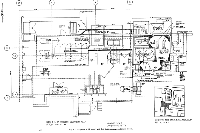
The replacement AHF supply and distribution system equipment would be located on Dock 8/8A (see Fig. 2.2). The dock would be modified to permit installation of the new supply system and related components. Utilities would be extended to the dock to service process equipment. The following process equipment modules would be prefabricated for installation at the modified dock: an AHF cylinder enclosure, including the AHF supply manifold; an AHF vaporizer skid; an AHF sump tank and transfer skid; and an AHF supply off-gas scrubber* assembly skid (Fig. 2.2).
Fig. 2.2. Proposed AHF supply and distribution system equipment layout.
The approximate dimensions of the AHF cylinder enclosure would be 1.2 m X 3.0 m X 1.5 m (4 ft X 10 ft X 5 ft) high. The AHF cylinder is approximately 75 cm in diameter X 205 cm (30 in. X 82 in.). Each cylinder head would have two valves provided with outlet caps and protected further by a removable hemispherical steel bonnet.
The framework for the AHF supply manifold and vaporizer skid would be approximately 1.2 m X 2.1 m X 3.6 m (4 ft X 7 ft X 12 ft) high. The manifold would include pressure relief devices, valves, pressure regulators, a pressure indicator, and cross-connections between the nitrogen and AHF systems. The vaporizer would be heated by band heating elements so that it would operate at 60· C (140· F) and 13.6 kg/6.5 cm2 (30 lb/in.2) gauge pressure. The saturated AHF vapor would be heated in a superheater, which is also heated by a band heating element, to deliver AHF at approximately 107· C (225· F) and 11.3 kg/6.5 cm2 (25 lb/in.2) gauge pressure to the fluidized-bed reactor. Both the vaporizer and superheater would be located within the AHF supply manifold and vaporizer skid.
Two saddle-type carbon steel supports would be designed to support the 946-liter (250-gallon) capacity AHF sump tank. The AHF sump tank would have a maximum allowable working pressure of approximately 6.8 kg/6.5 cm2 (15 lb/in.2) at a design temperature of 93· C (200· F). The tank would be equipped with a metering pump to transfer collected fluids for neutralization and disposal. Nozzles would be provided for AHF collection, transfer, and venting to the Venturi scrubber.* Process drain lines would be provided from the refrigerated AHF cylinder and vaporizer skids to the AHF sump tank. The discharge system would include a pump for transferring liquids to a transportable container.
The AHF supply off-gas scrubber system would consist of a Venturi scrubber followed by a packed column scrubber. Both scrubbers would sit atop the 14,384-liter (3,800-gallon) reservoir scrubber sump tank. Water would be used as the scrubbing medium. Any release would be captured by the scrubbers, and the resulting scrub solution would be neutralized with potassium hydroxide in a separate neutralization tank. The equipment would require an area of approximately 12.1 X 6.7 m (40 X 22 ft). The system would be designed to mitigate the effects of a design-basis accident* (see Sect. 4.3.3). The proposed system would be designed to fail safe in the event of a power loss.
2.1.1.2 Fluidized-bed reactor system
The proposed fluidized-bed reactor system would include the installation of new uranium oxide to uranium tetrafluoride hydrofluorination equipment consisting of a reduction (by hydrogen) fluidized-bed reactor (uranium trioxide to uranium dioxide), a hydrofluorination (by AHF) fluidized-bed reactor (uranium dioxide to uranium tetrafluoride), and supporting equipment. The new equipment would be located in an existing maintenance area of the B-1 Wing in Building 9212 (see Fig. 1.3) adjacent to the existing fluidized-bed reactors. The existing maintenance area would be isolated from the material access area* during demolition of the mezzanine, partitions, and stairways and during construction activities. The current fluidized-bed reactor system would remain operational throughout the construction project and would not be dismantled.
The proposed location would be cleared of unnecessary equipment and structures, and the existing supply and exhaust systems would be modified to make the area suitable for demolition and construction activities. In addition, the ventilation systems would be permanently upgraded through evaluation and replacement of the supply air and exhaust ductwork, as needed, to maintain the operations areas under a slight negative pressure to the surrounding atmosphere and adjacent noncontaminated areas.
The new fluidized-bed reactor system would consist of two cylindrical reactor vessels (reduction and hydrofluorination) within a heater. Uranium trioxide powder would be pneumatically* transported into the reduction fluidized-bed reactor. The reagent gas (hydrogen) would be preheated and fed into the bed with nitrogen to convert uranium trioxide into uranium dioxide. The off-gas from this reaction (excess hydrogen, water vapor, and nitrogen) would exhaust through a primary set of metallic filters and a secondary group of filters before exiting through a dedicated stack that would be monitored for uranium. The reactor bed, preheater, and filters would be contained within a single enclosed module. The enclosure would serve as a walk-in maintenance enclosure and would be ventilated through intake and outlet high-efficiency particulate air filters. A hydrogen detection system would be provided within the enclosure and in the general process area.
The hydrofluorination reaction would be accomplished by pneumatically conveying uranium dioxide from the reduction bed into the hydrofluorination reactor bed where AHF would be heated and fed with nitrogen into the reactor to convert uranium dioxide to uranium tetrafluoride. The hydrofluorination reactor-bed equipment would be similar in configuration to the reduction reactor and its supporting equipment with the addition of an off-gas HF scrubber system. The hydrofluorination reactor off-gas would contain HF, water vapor, and nitrogen. The HF would be scrubbed from the off-gas. Potassium hydroxide would be used as a scrubbing solution and would be supplied from the existing Dry Chemistry potassium hydroxide storage facility.
Two glovebox systems (Fig. 2.3) would be used to transfer the uranium powder product to and from the reduction beds. Each glovebox would house a canning, weighing, and sampling station. The canned uranium powder product would be inserted into and removed from the glovebox through a down-draft entrance hood.
Fig. 2.3. Glovebox systems for transfer of uranium trioxide.A central control and monitoring system for both the AHF supply and fluidized-bed reactor facilities would be located in an adjacent existing control room. Automatic systems would be used to perform routine operations from the control center. Closed circuit television and intercoms would be provided at the new fluidized-bed reactor location and the AHF supply dock facility. These systems would be monitored from the central control room.
The following general utilities would be provided to the B-1 Wing in Building 9212:
- new motor control centers;
- service and utility piping (e.g., steam, chilled water, condensate);
- emergency shower and eye wash stations;
- fresh air breathing stations;
- air sampling station;
- fire sprinkler system; and
- plant emergency notification, public address, fire alarm, and security systems.
Two new exhaust systems (i.e., fans, filters, stacks, and exhaust monitors) would be provided for the HF off-gas and enclosure exhaust.
Most of the process equipment would be designed and procured as completely preassembled and tested process modules to minimize field installation.
2.1.2 Operation
The operation of the proposed AHF supply system, the reduction fluidized-bed reactor module, and the hydrofluorination fluidized-bed reactor module are described in Sects. 2.1.2.1 through 2.1.2.3. Figure 2.4 is a flow diagram of the AHF supply and fluidized-bed reactor systems process. The new systems would be expected to be operational by December 1998, which is in the first quarter of Fiscal Year 1999. Personnel requirements for new systems would not differ from the existing systems.
Fig. 2.4. AHF supply and fluidized-bed reactor systems process block flow diagram.2.1.2.1 AHF supply system
The AHF cylinders would be similar to standard 1-ton chlorine cylinders, except they would not have safety pressure relief devices (fusible plugs). The vendor-provided cylinders would meet U.S. Department of Transportation specifications and would be inspected and hydrostatically tested* to 227 kg per 67.5 cm2 (500 lb/in.2) at least once every 5 years. Upon arrival at the Y-12 Plant and before being accepted into the facility, the AHF cylinders would be weighed. Multiple readings would be made to ensure accuracy. Overfilled cylinders would be rejected and returned immediately to the supplier on the same vehicle that delivered them.
The AHF cylinders would then be delivered directly to Dock 8/8A at Building 9212 on the vehicle that transported the cylinders to the Y-12 Plant from the chemical manufacturer. A forklift-type truck with cylinder grippers would be used to transfer the cylinders from the carrier vehicle into the AHF cylinder enclosure. The door of the cylinder enclosure would operate like a garage door. The cylinder would be lowered onto the rack in a horizontal position and then rotated in the rack to place the valves in a vertical line, one above the other. Thus configured, the lower valve would be used to discharge liquid AHF and the upper valve would be connected to the nitrogen supply. The rack would then retract into the cylinder enclosure. When the cylinder was inside the enclosure, the operator would remove the valve caps and connect the pigtails.* The pigtails would be connected to fixed piping transfer and nitrogen lines in the cylinder enclosure. The door to the cylinder enclosure would then be closed and locked. Manual valve controls, which would pass through the cylinder containment door, would be inserted into the cylinder valves.
The pigtails would then be checked for leaks using the purge and evacuation system. With the manual cylinder valves closed, the nitrogen valve, cylinder vent valve, and liquid HF transfer valve would be closed and the nitrogen leak-check valve opened. The leak-check valve would then be closed and the pressure in the lines would be monitored. If the pressure remained constant for 10 minutes, the pigtail connections would be considered tight. The nitrogen would then be vented to the primary off-gas treatment system through the vent valve as the transfer operation began.
The AHF cylinder would be protected from overpressure by a rupture disk that would be monitored by a current loop. An alarm would sound if the rupture disk released, breaking the circuit. Downstream of the rupture disk would be a pressure relief valve set to open at approximately 45.3 kg per 6.5 cm2 gauge (100 lb/in.2 gauge). A high-pressure switch with an alarm would be located between the rupture disk and the pressure relief valve to provide redundant pressure relief detection. A bypass valve would be provided around the pressure relief valve so that pressure buildup between it and the rupture disk due to leakage could be bled off. The bypass valve would be manually operated by Operational Maintenance Personnel when the system is down and purged to provide a method to relieve potential pressure between the system's rupture disc and relief valve as required per American Society of Mechanical Engineers Boiler and Pressure Vessel Code Section VIII. This valve would be opened to relieve any built-up pressure prior to maintenance (i.e., rupture disc replacement) on the system. This line would be vented directly to the scrubber system.
The cylinder enclosure and the vaporizer enclosure would be maintained at lower-than-atmospheric pressure by the Venturi scrubber. No provision for makeup air would be necessary because neither enclosure is completely leak tight and the Venturi scrubber could be operated at no-gas-flow conditions, unlike an induced draft fan. This operation would minimize corrosion that could result from fugitive emissions of AHF reacting with moisture-laden air.
To conduct a batch transfer from the AHF cylinder into the AHF manifold and vaporizer, transfer valves would have to be set in their proper positions. Transfer into the vaporizer tank would require that the tank first be vented to the primary off-gas system and that the inlet liquid AHF line isolation valve be opened.
After the vaporizer tank valves had been properly set, the operator would correctly configure the cylinder transfer valves. The vapor space above the liquid in the cylinder would be pressurized with nitrogen, pushing the liquid AHF through a dip tube* assembly that would extend within 1.3 cm (1/2 in.) of the bottom of the vessel.
Transfer would begin when the liquid AHF transfer valve was opened. A high-level switch* would be triggered when a batch level of AHF in the vaporizer is reached. This switch automatically would close the transfer valve to prevent overfilling of the vaporizer. A control panel would alert the operator that the transfer was complete. A second, independent high-high-level switch would be triggered if the batch feed tank continued to fill with AHF. This switch would be interlocked with a second valve independent of the first high-level switch valve. These features would provide redundant overfill protection for the vaporizer. Once a batch of AHF had been transferred and the AHF cylinder vented, the vaporizer and superheater would be heated to supply gaseous AHF to the hydrofluorination fluidized-bed reactor.
When the AHF cylinder was empty, the operator would purge the AHF lines with nitrogen through the off-gas treatment system so that the cylinder could be removed from the cylinder enclosure. After the purge cycle, the AHF cylinder enclosure would be opened, and the operator would close the vent valve, disconnect the pigtail, and remove the empty cylinder from the enclosure.
A lift truck would be used to move the empty cylinder from its rack to a pallet for pickup by the vendor. During this and all routine operations involving the cylinder, the operators would continue to wear rubber chemical aprons, rubber gloves, face shields, and goggles to protect themselves from accidental exposure to AHF.
The AHF supply off-gas scrubber system would be operated continuously during cylinder change-out and transfer activities. To begin operation, one of the two installed centrifugal recirculation pumps would be selected as the primary; the other would be used as a standby. The primary pump would be started using push-button switches. Flow indicators would be used to adjust the manual throttling valves to obtain the desired flow distribution in the recirculation line.
Scrubbed gases from the Venturi scrubber, which would remove up to 95 percent of the HF present in the gas stack, would flow upward through the packed column scrubber. The packed column scrubber further reduces the HF level, and the 0.1 percent remaining would be discharged to the atmosphere. Differential pressure indicators would be used to monitor for flooding of the packed column and to evaluate the efficiency of the high-energy Venturi scrubber. The top of the stack would be approximately 15 m (50 ft) above the ground. Actual release rates are not known; however, the existing system allows releases to be vented directly to the atmosphere and these do not exceed applicable standards (see Sect. 3.1). Approximately 99 percent of the HF entering the packed column would be removed, resulting in an overall system removal efficiency of 99.9 percent. Scrub solution would be collected in the scrubber sump tank, which is the common circulant holding tank for both the Venturi and the packed column scrubbers. HF absorbed by the Venturi and packed column scrubbers would be neutralized in a separate tank with potassium hydroxide. Liquid wastes generated by the scrubbing process would be transported by tanker truck to the Y-12 Plant Central Pollution Control Facility.
The spill retention basin surrounding the AHF supply off-gas scrubber system would drain to a sump. An air-operated diaphragm pump would be used to empty the dike into a tanker in the event of a spill. The sump could also be emptied into the scrubber sump tank. The roof over Dock 8/8A would be extended to minimize rainwater collection in the sump. Should rainwater be captured in the sump, it would be sampled for pH and uranium and discarded to the storm sewer, if chemical constituents are within National Pollutant Discharge Elimination System (NPDES) permit limits. Otherwise, the rain water would be added to the spent potassium hydroxide tank and eventually transported by truck to the Y-12 Plant Central Pollution Control Facility.
2.1.2.2 Reduction fluidized-bed reactor module
Uranium trioxide would be transferred in cans through an airlock into the uranium trioxide transfer glovebox. The uranium trioxide would be loaded into a receiver and the cans would be cleaned and weighed for inventory purposes. The uranium trioxide would be transferred pneumatically into the reduction fluidized-bed reactor by a positive pressure system using nitrogen gas. Nitrogen would be forced through the distributor plate in the bottom of the reduction fluidized-bed reactor during all transfer steps to minimize the potential for powder to settle and lodge in the distributor.
After the powder was transferred into the reduction fluidized-bed reactor, a heater would bring the reactor and the powder up to near reaction temperature [566· C (1,050· F)]. When the bed was near the reaction temperature, the nitrogen flow would be reduced as the hydrogen flow was simultaneously initiated, keeping the overall gas flow constant as the type of gas changed. The fluidization controller would control the total flow during this operation. When the reaction had ended, the moisture analyzer in the reactor off-gas line would indicate that no more water was being generated by the product. The hydrogen flow would be maintained for a set period of time after the reaction was complete and then the fluidizing gas would once again be switched to nitrogen only. The product, uranium dioxide, would be transferred to the hydrofluorination bed through a pneumatic transfer line. The bottom of the reduction fluidized-bed reactor would be cylindrical and up to 15 cm (6 in.) in diameter to facilitate fluidization of the powder.
The reduction fluidized-bed reactor and associated equipment would be housed in a maintenance enclosure to minimize the potential for the spread of radiological contamination. The equipment primarily requiring maintenance would be anticipated to be the filters that prevent uranium-containing powder from being drawn into the process vent. Nitrogen would be periodically pulsed back through the primary filters to rid them of clinging powder and to increase the time between filter change-outs. Personnel would only enter the facility to perform maintenance activities when the fluid beds were not in operation and after the systems had been purged and the supply valves locked out.
2.1.2.3 Hydrofluorination fluidized-bed reactor module
Uranium dioxide would be pneumatically transferred from the reduction fluidized-bed reactor into the hydrofluorination fluidized-bed reactor. Nitrogen would be forced through the distributor plate in the bottom of the hydrofluorination fluidized-bed reactor during all transfer steps to minimize the potential for powder to settle and lodge in the distributor.
After the powder had been transferred into the reactor, a heater would bring the reactor and the powder up to near reaction temperature [232· C (450· F)]. When the bed neared the reaction temperature, the temperature in the reactor would be controlled by the flow rate of AHF. Because the reaction of AHF and uranium dioxide produces extreme heat, the flow rate of the AHF would govern the reactor temperature. The fluidization controller would control the total gas flow during this operation. When the reaction had ended, the moisture analyzer in the reactor off-gas line would indicate that no more water was being generated by the product. The AHF flow would be maintained for a set period of time after the reaction was complete, and then the fluidizing gas would once again be switched to nitrogen only.
After the product (uranium tetrafluoride) had cooled, it would be transferred pneumatically into the uranium tetrafluoride receiver. The uranium tetrafluoride receiver would be located above the uranium tetrafluoride canning glovebox. Transfer from the receiver to cans would be accomplished by gravity. During the canning step, a sample would be taken to be tested for purity. A scale (for weighing the uranium tetrafluoride) and a housekeeping vacuum (for cleaning up loose uranium tetrafluoride) would be incorporated into the glovebox. Canned uranium tetrafluoride would be transferred out of the glovebox through an airlock and would be stored in existing facilities to await laboratory analysis and further processing (reduction to uranium metal). The bottom of the hydrofluorination fluidized-bed reactor would be cylindrical and up to 15 cm (6 in.) in diameter to facilitate fluidization of the powder.
The hydrofluorination fluidized-bed reactor and associated equipment would be housed in a maintenance enclosure to minimize the potential for the spread of radiological contamination. Personnel would only enter the facility once a month to perform maintenance activities. The equipment primarily requiring maintenance would be the filters that prevent uranium-containing powder from being drawn into the process vent. Nitrogen would be periodically pulsed through the primary filters to rid them of clinging powder and to increase the time between change-outs.
An off-gas treatment system would be provided for the hydrofluorination fluidized-bed reactors. This scrubber would be designed to remove 99 percent of the HF and would accommodate a flow of approximately 27 kg (60 lb) of HF per hour.
2.1.3 Emissions, Effluents, Wastes
The ways in which the proposed new AHF supply and fluidized-bed reactor systems would differ from the existing systems are described in Sects. 2.1.3.1 through 2.1.3.3.
2.1.3.1 Emissions
The new AHF supply system would allow less than 0.1 percent of gaseous emissions from the system to escape into the air as compared to the present system, which allows releases of 100 percent of gaseous emissions. Perimeter monitors in operation until 1994 indicated that ambient fluoride concentrations are well below standards established by the State of Tennessee (Energy Systems 1994).
Emissions from the existing and new fluidized-bed reactor systems are expected to be comparable; however, the change in design involves complete secondary containment of the reactors, which would provide an additional barrier between workers and the primary process containment.
Stack Emissions. The existing AHF system is permitted with the State of Tennessee. This permit allows for emissions monitoring through engineering calculations using classified material balance data. The State of Tennessee has personnel who have proper clearances to review the calculations and source data. The amount of material released equals the amount of material used in the process, less the amount of material captured in the filtration/emission control systems. Improved emission controls, such as the additions of an AHF scrubber in the exhaust stack for the fluidized-bed reactor, and administrative and process controls, were implemented in the existing system after the 1992 release. When operating, the existing system allows fugitive gases, including purges and pressure releases, to be vented directly to the atmosphere. For the proposed action, routine process emissions and fugitive emissions would be routed through an off-gas treatment system scrubber before release to the atmosphere. This would allow less than 0.1 percent of fugitive emissions from the system to escape.
Ambient Air Monitoring. Because the Y-12 Plant is in an area of ambient air quality attainment, the State of Tennessee does not require ambient air sampling for fluorides. The TDEC standard for fluoride emissions is 1.6 ng/m3 for a 7-day average. Periodic fluoride sampling was conducted at the Y-12 Plant beginning in the late 1950s or early 1960s, with continuous sampling conducted beginning in 1986. Eleven samplers encircling the Y-12 Plant filtered ambient air to collect fluorides. Average 7-day fluoride concentrations at these stations were only a small fraction (typically less than 2 percent) of the TDEC standard for non-attainment areas. In accordance with an agreement with TDEC/DOE Oversight Division, perimeter ambient air fluoride monitoring was discontinued at the Y-12 Plant in December 1994.
Accidental Releases. There have been no federal or state violations of the state air permit from the AHF process at the Y-12 Plant.
2.1.3.2 Effluents
The new AHF supply system would prevent release of effluents from the supply dock because all liquid discharge would be routed to the sump. The existing system allows water released from the deluge system to flow into storm drains. No effluents would be discharged from the proposed fluidized-bed reactor systems.
2.1.3.3 Wastes
Liquid waste resulting from operation of the proposed new AHF and fluidized-bed reactor systems and the existing systems would be comparable. Spent scrubber waste would consist of residual potassium hydroxide, potassium fluoride, and water. During normal operations, the scrubber for the proposed fluidized-bed reactor system would remove residual HF from the process off-gas stream, just as the current system does.
The proposed new scrubber in the Dock 8/8A area would use water as the scrubbing medium. Under normal operations, no waste would be generated by this scrubber; waste from this scrubber would be generated only by operation during an accidental release. In that case, the spent water scrubbing solution (which would be a weak hydrofluoric acid solution) would be neutralized with potassium hydroxide. The treated wasted would then consist of residual potassium hydroxide, potassium fluoride, and water. The waste stream* from the scrubbing process would be processed through the Y-12 Plant's Central Pollution Control Facility, just as the current waste stream is processed.
2.2 NO-ACTION ALTERNATIVE
The no-action alternative is to continue operating the existing AHF supply and fluidized-bed reactor systems. The existing AHF and Fluidized Bed Reactor systems were originally designed 40 years ago and have been recently upgraded in 1992 and 1994 to address improvements as a result of an HF release incident in 1992. The no action alternative would involve continuing operation of the current upgraded systems, as is (reference Sect. 1.1). The current system is assessed against the proposed action in Table 2.1.
2.3 EXTENSIVE MODIFICATIONS OF CURRENT AHF SUPPLY AND FLUIDIZED-BED REACTOR SYSTEMS
The existing AHF supply and fluidized-bed reactor systems have been modified several times in the past 40 years to provide upgrades in operational safety. However, there is not enough space in the existing AHF location to allow for the full complement necessary to extend the systems design life, while maintaining operations, and consurrently construct systems which meet DOE Orders DOE 6430. 1A and DOE-STD-1020, and industrial guidelines for the safe handling of AHF. In order to extend the current systems life and construct systems which meet the new design criteria, the existing system would have to be out of service for extended periods of time (years) which does not support DOE mission requirements. This alternative was reviewd during the system site analysis (Energy Systems 1992a) and removed from consideration. Therefore, this is not a reasonable alternative to satisfy the need for action.
2.4 TERMINATION AND SHUTDOWN OF AHF SUPPLY AND FLUIDIZED-BED REACTOR SYSTEMS
Under this alternative, DOE would terminate and shut down the AHF supply system and fluidized-bed reactor operations. As one of the largest handlers of enriched uranium in the world (United States Congress 1993), the Y-12 Plant provides a broad spectrum of enriched uranium handling, processing, and storage capabilities that are not available at any other single DOE site. The AHF supply and fluidized-bed reactor systems are key processes for the chemical recovery and recycling of highly enriched uranium. The recovery and recycling of highly enriched uranium are unique capabilities of the Oak Ridge Y-12 Plant and are needed to fulfill several DOE mission requirements. The mission requirements that this alternative would not meet are:
- interim and long-term storage of enriched uranium at a location where prestorage processing capability is available to support continued weapons dismantlement;
- nonproliferation goals by converting uranium salvage from retired weapons to alternate forms, which are more readily accountable;
- maintenance of nuclear competence through weapons life extension and providing requested specification-grade uranium for weapons component fabrication and other special needs; and
- other purposes of national security (DOE 1994b and Energy Systems 1994).
DOE also needs to process enriched uranium to provide material control, accountability, and maximum utilization of existing interim storage space and to consolidate, process, and manage on an interim basis any enriched uranium that is not needed at other sites. Additionally, only the Y-12 Plant has the processing capabilities necessary for disassembly of secondaries (weapons components) received from the Pantex Plant in Amarillo, Texas. Prestorage processing capability could not be added at other sites in the near term (DOE 1994a). Therefore, termination and shutdown of the AHF supply and fluidized-bed reactor systems would not meet DOE's mission requirements and is not a reasonable alternative.
2.5 USE OF OTHER DOE OR NON-DOE FACILITIES
As noted in Sect. 2.4, recycling and recovery of highly enriched uranium is a unique capability of the Y-12 Plant. The chemical and waste treatment infrastructure, trained workforce, and necessary security are in place at the Y-12 Plant. As an alternative to the proposed action, use of other facilities is cost prohibitive and, therefore, is not considered reasonable and will not be evaluated further.
2.6 ALTERNATIVE TECHNOLOGIES
There are other processes under development which could theoretically replace parts of the proposed (and current) systems. The most promising technology considered is Saltless Direct-Oxide Reduction. However, the current state of development of this technology is at the laboratory scale and is unproven at production scale. Further development would require substantial time and funding resources to complete proof of principal and production scale-up. The cost and timeframe associated with this alternative are unreasonable and not acceptable to support the purpose and need and, therefore, will not be considered further.
2.7 ALTERNATIVE SITES AT THE Y-12 PLANT
Alternate locations for the proposed action, other than adjacent to Building 9212 in the Y-12 Plant, were not considered feasible because of the extensive system requirements for handling and storing enriched uranium material, within a secured and geometrically configured criticality safe Y-12 Plant area. Design and construction of an additional secured area at an alternate site within the Y-12 Plant is cost prohibitive, technologically redundant, and does not fit long range plans to downsize the plant footprint, therefore, further consideration of alternative sites at the Y-12 Plant was eliminated.
3. AFFECTED ENVIRONMENT
Most of the information in this chapter was taken from the Oak Ridge Reservation Annual Site Environmental Report for 1993(Energy Systems 1994). The Oak Ridge Reservation's approximately 14,300 hectares (35,300 acres) lie within the corporate boundaries of the City of Oak Ridge, Tennessee. The Y-12 Plant is situated in Bear Creek Valley at the eastern boundary of the Oak Ridge Reservation, about 4.8 km (3 miles) from the population center of the City of Oak Ridge. The plant site is bounded on the south by Chestnut Ridge and on the north by Pine Ridge and lies on the valley floor and northern slope of Chestnut Ridge. The Y-12 Plant industrial complex occupies approximately 1,376 hectares (3,400 acres) and has a surrounding buffer zone of about 1,233 hectares (2,800 acres).
The estimated residential population within an 80-km (50-mile) radius of the Oak Ridge Reservation is approximately 880,000. A major urban center, Knoxville (population approximately 165,000), is located about 32 km (20 miles) to the east. The city of Oak Ridge has a population of about 27,000. The approximate populations and locations of other towns near the Oak Ridge Reservation are as follows: Oliver Springs (population 3,400), 11 km (6.8 miles) northwest; Clinton (population 9,000), 16 km (10 miles) northeast; Lenoir City (population 6,100), 11 km (6.8 miles) southeast; Kingston (population 4,600), 11 km (6.8 miles) southwest; and Harriman (population 7,100), 13 km (8 miles) west.
The population within 80 km (50 miles) of the Oak Ridge Reservation consists of people who live in the area and people involved in other industrial activities, schools, recreational activities, and health care facilities, as well as those traveling through the area. In December 1992, the Y-12 Plant employed 6,575 people.
The following would not be affected by the proposed action or alternatives: floodplains; wetlands; threatened, endangered, or candidate species and/or their critical habitat, and other special status; prime or unique farmland; state or national parks, forests, conservation areas, or other areas of recreational, ecological, scenic, or aesthetic importance; wild and scenic rivers; natural resources (e.g., timber, range, soils, minerals, fish, wildlife, water bodies, aquifer); and Native Americans' concerns.
3.1 AIR QUALITY
Periodic fluoride sampling was begun in the late 1950s or early 1960s and ceased in December 1994 (Shelton 1995). Eleven samplers encircling the Y-12 Plant filtered the ambient air continuously to collect fluorides. In 1986, the sampling time was increased to continuous, with sample filters being exchanged every 7 days so that the data could be compared to the Tennessee Department of Environment and Conservation's standard of 1.6 mg/m3 for a 7-day average. Average 7-day fluoride concentrations at the Oak Ridge Reservation stations were only a small fraction of the Tennessee Department of Environment and Conservation standards [typically less than 2 percent (Energy Systems 1994)]. This standard applies only to areas that do not meet ambient air quality criteria.
Because the Y-12 Plant is in an area of ambient air quality attainment, the State of Tennessee does not require sampling. Dispersion modeling using Y-12 Plant meteorological data can be used to predict or estimate exposure in the event of a release and spot sampling can be conducted to confirm model results. Currently, the AHF system is not operating because uranium salvage and recycling operations are on hold. New and improved emission controls such as the addition of an AHF scrubber in the exhaust stack for the fluidized-bed reactor and administrative and process controls were implemented after the 1992 release (Energy Systems 1993d).
3.2 WATER RESOURCES
The Y-12 Plant is located in the Bear Creek and East Fork Poplar Creek drainage basins of the Clinch River.
The Bear Creek watershed has a drainage area of 19.4 km2 (12 miles2). The headwaters of Bear Creek originate near the western end of the Y-12 Plant. The creek flows westward through Bear Creek Valley for about 7 km (4.5 miles), then turns northward to flow into East Fork Poplar Creek.
The East Fork Poplar Creek drainage basin has an area of 77.2 km2 (30 miles2). The headwaters of East Fork Poplar Creek consist of springs that originate on the northwestern slope of Chestnut Ridge near the Y-12 Plant. The stream is contained in culverts through much of the western end of the Y-12 Plant before it enters a rip-rap channel. Just east of the plant boundary, East Fork Poplar Creek flows into Lake Reality. Lake Reality is a retention basin with gates that can be used to contain contaminated water and minimize off-site releases in the event of a spill. From the outfall of Lake Reality, the creek flows 23.7 km (15 miles) to its confluence with Poplar Creek, a tributary of the Clinch River. Many storm water drains at the Y-12 Plant discharge to East Fork Poplar Creek; thus, it is the likely receiving body of water for any construction-related sediment erosion. The construction location for the proposed action is approximately 1,070 m (1,170 yd) from the channel of East Fork Poplar Creek.
3.3 SOIL
Based on recent radiological and excavated soil surveys from projects at the same location as the proposed action, no contaminants are likely to be present in the soil. However, based on operational process knowledge, there is the potential to discover enriched uranium oxide in the soil. Although no further characterization of the soil is planned, continuous radiological surveying of excavated soil would be performed to monitor for this potential. Personal protection equipment requirements beyond Level D would not be required for excavation workers unless continuous surveys indicate otherwise.
3.4 ARCHAEOLOGICAL AND CULTURAL RESOURCES
An evaluation of the facilities within the Y-12 Plant for their potential listing on the National Register of Historic Places was performed in 1995. Building 9212 was found to be eligible for inclusion in the National Register of Historic Places. A programmatic agreement concerning management of historical properties and cultural resources at the Oak Ridge Reservation was executed among the DOE Oak Ridge Operations Office, the Tennessee State Historic Preservation Officer, and the Advisory Council on Historic Preservation on May 6, 1994 (Advisory Council on Historic Preservation 1994). The DOE Oak Ridge Operations Office will develop a management plan for historical and cultural resources as part of this agreement. By carrying out the terms of this agreement, DOE will have fulfilled its responsibilities under Sections 106 and 110 of the National Historic Preservation Act and the regulations of the Advisory Council on Historic Preservation. DOE is preparing a Cultural Resources Management Plan for the Oak Ridge Reservation, which will include a survey to identify significant historical properties. Building 9212 will be included in the management plan, a draft of which is scheduled for completion in May 1996.
3.5 BACKGROUND RADIATION
The exposure rate from external natural background radiation (i.e., radiation from cosmic and terrestrial sources) across the state of Tennessee averages about 42 mrem/year, which is similar to the average U.S. external exposure rate of 55 mrem/year. Natural background radiation is derived from both external and internal sources. External sources include cosmic rays and naturally occurring radioactive materials in the earth (NCRP 1987).
External radiation exposure rates are measured at a number of locations on and off the Oak Ridge Reservation. The average total dose (including background) at perimeter air monitoring stations around the Oak Ridge Reservation during 1993 was 49 mrem. With the exception of two locations, all measured exposure rates outside the Oak Ridge Reservation boundaries are near background levels. The two exceptions are a stretch of bank along the Clinch River and a section of Poplar Creek that flows through the K-25 Site on the Oak Ridge Reservation. The Clinch River bank is affected by air-scattered radiation derived from cesium used in experiments on a nearby field. The radiation field along Poplar Creek is due to storage areas within the K-25 Site.
4. ENVIRONMENTAL IMPACTS
4.1 DEMOLITION AND CONSTRUCTION
All demolition and construction activities associated with the proposed project would be conducted in accordance with Y-12 Plant, Energy Systems, and DOE environmental policies. A best management practices plan would be prepared during the design phase and implemented to minimize the potential release of pollutants by means of storm runoff to the waterways on the plant site. The requirements of the best management practice plan would be made an integral part of the construction plans and specifications.
4.1.1 Air Quality
Impacts to air quality would be short-term and localized. Localized means that emissions would be expected to remain within the plant boundaries. Dust would be generated during construction activities and exhaust emissions would be produced from operation of construction vehicles and other internal combustion-driven equipment.
Best management construction practices would be employed to minimize dust generation during construction. Dust control measures would include respiratory protection or dust suppression techniques for interior demolition activities. For example, for removal of piping insulation, sheetrock joint compound, roofing, or flooring materials that contain asbestos, negative-pressure enclosures would probably be needed. Stainless steel, galvanized ductwork, Monel metal*, and paint contain materials that are potential respiratory hazards if aerosolized as a respirable dust or fume during demolition. Release of these materials would necessitate that workers use respiratory protection. Air emissions related to demolition and construction would not cause exceedance of any regulatory limits.
4.1.2 Soils/Topography
Impacts to soil and topography would be minimal. Demolition and construction would entail minor excavation (primarily associated with removal and relocation of the Brake Press Pavilion and installation of a new section of storm drain) and grading of the site. The area to be disturbed during excavation would be approximately 65 m2 (700 ft2).
4.1.3 Water Quality
Erosion and sediment control would be provided to minimize the transport of sediment into storm sewers or beyond the limits of the construction. Construction would be based on the Y-12 Plant Spill Prevention Control and Countermeasure Plan (Energy Systems 1989). Erosion control measures to be employed during excavation and grading include temporary control measures for slope protection and controls to reduce erosion, sedimentation, and water pollution by using mulches, grasses, temporary silt fences and other controls such as filter cloth. As a first step in construction, workers would install inlet sediment filters, perimeter barriers, and other measures to deter erosion and transport of sediment associated with construction activities before upslope land disturbance takes place. Earthen structures, such as dams, berms, and diversion ditches, would be seeded and mulched. Silt fences would be installed to reduce the quantity of sediment and velocity of flow to downstream areas. Silt fences are constructed of 1.7-m (5.5-ft) long wood or steel posts with 1-m (3-ft) high wire fencing as backing for the geotextile filter fabric, typically consisting of pervious sheets of synthetic material. Immediately after each rainfall, and daily during prolonged rainfall, the silt fences would be inspected and repaired, as needed; sediment deposits would be removed after each storm event.
The natural waterway most likely affected by sediment runoff would be East Fork Poplar Creek. Many of the storm drains at the Y-12 Plant discharge to this creek. Because very little soil would be disturbed during construction, the amount of sediment contributed, even with a breach in silt fencing, would be small and no effects on water quality or biological receptors would be expected.
4.1.4 Natural and Historic Resources
The demolition and construction activities of the proposed action would occur within a heavily industrialized setting in an area dominated by buildings, parking lots, and roadways. Two small wetlands are located within the eastern section of the Y-12 Plant, neither of which is near the proposed site (Hardy, Pounds, and Cook 1992). Building 9212 is not within the 100-year floodplain* (Energy Systems 1993c). Because no natural habitat would be disturbed, no federally or state-protected plant or animal species would be affected during the demolition or construction phase.
Prehistoric or historic archaeological sites circa 1940 or earlier would not be affected by the proposed action (DuVall 1992). An evaluation of the facilities within the Y-12 Plant for their potential listing on the National Register of Historic Places was performed in 1995 with Building 9212 becoming a listed property. The State Historic Preservation Office concurred that the proposed action would not adversely affect this property provided that existing equipment is documented photographically, that a copy of this documentation is submitted to the State Historic Preservation Office, and that a copy is retained at the facility for research use.
4.1.5 Health and Safety
The health and safety hazards facing workers during demolition and construction are: potential exposure to low-level radioactive contaminants during soil excavation in the area of Dock 8/8A and demolition inside B-1 Wing of Building 9212, inhalation of dust during demolition of the Brake Press Pavilion and inside Building 9212, inhalation of asbestos fibers during demolition inside Building 9212, and construction accidents.
All demolition would be performed by workers familiar with radiation hazards, would be closely monitored by the Energy Systems and/or M-K Ferguson Health and Safety Office, and would be performed in accordance with all DOE and Occupational Safety and Health Administration policies and regulations. A thorough radiological, chemical, and asbestos characterization survey of both Dock 8/8A and B-1 Wing of Building 9212 has been conducted.
Portions of the eastern end of the B-1 Wing in Building 9212 would have to be demolished to construct the new fluidized-bed reactor system. The facility's ventilation gaskets potentially contain polychlorinated biphenyls (PCBs); however, workers, by using proper personal protective equipment, could easily remove potentially contaminated gaskets without exposure.
Health physics surveys indicate radiological contamination on Dock 8/8A (but not adjacent soil) and B-1 Wing maintenance shop areas. The contamination on the dock is fixed and is primarily fixed in B-1 Wing. On the basis of the health physics surveys and recent construction projects around Dock 8/8A, Y-12 Radiological Engineering and M-K Ferguson have outlined protective equipment requirements for the demolition work (Table 4.1) (England 1992). These requirements would be documented in a Safety Work Permit and, where necessary, a Radiation Work Permit before demolition work, or if contamination were detected, during dock demolition activities. Exposure to workers during construction/demolition would thus be within acceptable limits. As described in Sect. 3.3, the only hazardous material potentially present in the soil surrounding Dock 8/8A is enriched uranium oxide. Excavation activities would be of limited duration, and therefore potential exposure would be limited. Although actual exposures to unprotected workers have not been determined, the use of personal protective equipment would ensure that workers would receive no unacceptable exposure. The protective equipment requirements listed below may change as additional field surveys are completed and site conditions warrant.
4.1.6 Waste Management
Most demolition debris would be expected to be classified as low-level contaminated solid waste. It would be necessary to cut these materials into sizes that could be placed in special containers for waste storage. A standard container for waste storage is the metal B-25 box, which has approximate dimensions of 1.2 m X 1.8 m X 1.2 m (4 ft X 6 ft X 4 ft) deep and has an approximate volume of 2.6 m3 (96 ft3). Therefore, cutting dimensions must be less than 1.2 X 1.8 m (4 X 6 ft). Total volume of low-level waste is expected to be 64.8 m3 (2400 ft3), which would fill 25 B-25 boxes. A comparable volume of noncontaminated waste is also anticipated; this waste would be disposed in the Y-12 Plant landfill.
Clothing would be collected daily and returned to a regulated laundry facility. Scaffolding, plastic sheets, and plywood would be boxed. High-efficiency particulate air filters and ductwork that were removed would be surveyed for radionuclide* contamination and boxed for storage. Further processing of high-efficiency particulate air filters could be required if significant amounts of radionuclides were collected. All containerized waste would be stored in waste-storage vaults at the K-25 Site.
4.2 IMPACTS OF INCIDENT-FREE OPERATION
4.2.1 Air Quality
Routine process emissions of AHF would be routed through an off-gas treatment system scrubber before release to the atmosphere. Therefore, the potential for an uncontrolled or untreated AHF release to the atmosphere would be greatly decreased compared to current operations. The volume of material through the system would not increase relative to the current system, so the decrease in release of AHF would not be offset by increased volume.
Table 4.1. Protective equipment requirements for demolition workDock 8/8A Excavation (Soil)a
- Hard hats
- Safety shoes
- Safety glasses
Dock 8/8A Demolition Work
- Half-face respirator
- Type H particulate cartridge
- Safety glasses
- Hard hats
- Safety shoes
- Gloves
- Paper suits, double clothing for welding or burning
- Area roped off at a minimum of 10 ft and posted as a Half-Face Respirator Area during dust-producing activities
- The area shall be deemed a Radiological Area - Airborne Contamination Area
- All personnel and material shall be monitored by Health Physics before leaving the Radiological Area
- At completion of work, the area shall be cleaned, surveyed by Health Physics, and deemed free from contamination. The area shall then be made a Non-Radiological Area
B-1 Wing Maintenance Shop
- Full-face respirator
- Type H particulate cartridge
- Safety glasses
- Safety shoes
- Hard hats
- Gloves
- Paper suits, double clothing for welding or burning
- Area roped off at a minimum of 10 ft from the work area and posted as a Full-Face Respirator Area during dust-producing activities
aIf contamination (enriched uranium oxide) were to be detected, protective equipment requirements would be
the same as for Dock 8/8A demolition work.
4.2.2 Health and Safety
The proposed actions are designed to reduce the risk of an unacceptable exposure to the worker population and the general public. Automated control features, leak detection systems, and fugitive emission and emergency release HF capture and treatment systems would be provided. The control systems would be designed to prevent uncontrolled releases of AHF emissions to the atmosphere, eliminating any potential threat to the general public and workers in the vicinity.
4.2.3 Waste Management
Once operational, the air emission control systems would routinely generate wastes that must be disposed. Off-gas treatment systems for the hydrofluorination fluidized-bed reactor systems would use potassium hydroxide scrubbers. Spent potassium hydroxide scrubber solution (containing potassium fluoride) would be transported to the Central Pollution Control Facility for treatment and disposal (see Section 2.1.3.3). Waste treatment operations are under review and may in the future regenerate the potassium hydroxide from the spent scrubber solutions.
4.3 IMPACTS OF ACCIDENTS
4.3.1 Hazardous Materials
Radioactive, fissile, and toxic materials are associated with the proposed action. Their characteristics are described below.
4.3.1.1 Toxic materials
The principal toxic substances associated with the proposed action are AHF, potassium hydroxide scrubber solution, uranium oxides (uranium dioxide and uranium trioxide) and green salt (uranium tetrafluoride).
AHF is the greatest concern because it is present in large quantities, produces severe health effects at relatively low concentrations, and is readily vaporized. [The boiling point at atmospheric pressure is 19.5· C (67· F).] Although the other chemicals are about equally toxic in terms of permissible concentrations, they are present in smaller quantities and do not easily become airborne. (Uranium is present as coarsely divided solids and potassium hydroxide is present in aqueous solution.)
Short-term (acute) exposure to AHF at relatively high concentrations can result from accidents; therefore, permissible doses (intakes) are suggested by several published limits. The Immediately Dangerous to Life and Health concentration is 30 parts per million (25 mg/m3) (NIOSH 1990). Immediately Dangerous to Life and Health is the concentration from which one could escape within 30 minutes without a respirator and without experiencing any escape-impairing (for example, severe eye irritation) or irreversible health effects. At a typical breathing rate of 1 m3/hour, a 30-minute exposure at the Immediately Dangerous to Life and Health concentration produces an inhaled dose of 12.5 mg.
ERPGs are concentration values that are developed specifically for accident evaluations and are published by the American Industrial Hygiene Association (AIHA 1989). Three ERPG levels are defined, each of which is based on a 1-hour exposure. Concentrations below ERPG-1 are expected to produce, at most, minor effects. ERPG-2 is the concentration below which no serious or irreversible health effects are predicted (20 parts per million or 17 g/m3 for AHF). ERPG-3 is the maximum concentration in air below which exposure could occur without life-threatening health effects (50 parts per million or 42 mg/m3 for AHF). At a typical breathing rate of 1 m3/hour, the corresponding AHF doses for 1-hour exposure are 17 mg (at ERPG-2) and 42 mg (at ERPG-3).
4.3.1.2 Radioactive materials
Uranium, enriched up to 93 percent uranium-235, is processed in the fluidized-bed reactors and may be present in the off-gas streams. Internal radiation doses could occur from inhalation or ingestion of solids or solutions. Because uranium is primarily an alpha emitter, there is little risk from external radiation. Significant doses require that uranium enter the body, typically through inhalation, ingestion, or an open wound. Inhalation is the only significant exposure pathway for accidents related to the proposed action.
Only inhaled particles with diameters less than 5 to 10 microns will reach the lungs. The fraction of particles in an aerosol that are in this size range is commonly referred to as the respirable fraction. The only sources of airborne uranium are the coarse granules that comprise the feed materials to the two reactors. Measurements of particle size distribution indicate that the respirable fraction in these materials is so low as to be considered zero (Energy Systems 1993d). For this reason, airborne uranium is not expected to produce health consequences.
4.3.1.3 Fissile materials
The uranium that is processed in the fluidized-bed reactors is enriched to 93 percent uranium-235 and is therefore capable of a self-sustaining fission reaction. The potential for a criticality accident is discussed in Table 4.2.
4.3.2 Accident Identification
A Preliminary Hazards Analysis (PHA) has been completed for the proposed project. The PHA was performed to identify candidate and significant Safety Class Systems, Components, and Structures. Accidents described in this EA are taken from the PHA, which included identification of basic failure modes and accident scenarios leading to releases of AHF.
The project is being designed so that the annual probability of unacceptable damage to these new facilities (specifically the portion designated as moderate hazard) from natural phenomena events is no greater than 1 in 10,000, as required by DOE Order 5480.28 (DOE 1993). The associated natural phenomena hazards [such as earthquake, wind/tornado, or flood, as defined in DOE-STD-1020-94 (DOE 1994c)] at this Oak Ridge site are the largest earthquake expected to occur in 2000 years (19 Peak Ground Acceleration at top of rock), the fastest-mile wind/tornado speed expected to occur in 50,000 years (113 miles/hr), and the maximum flood expected in 10,000 years.
4.3.3 Accident Analysis
Table 4.2 lists the accident scenarios considered in this analysis and provides discussion on potential impacts.
Table 4.2. Accident scenarios and potential impacts| Accident scenarios | Potential impacts |
| Cylinder Handling | An accident that occurs during transport between the delivery truck and the secondary confinement structure, such as dropping a cylinder during lifting, could release the entire contents of one cylinder to the atmosphere at ground level. However, drop tests of nearly identical 612-kg (1,350-lb) cylinders, performed for the U.S. Army, showed that the cylinders can be expected to survive impacts on their sides or ends equivalent to a 12-m (40-ft) drop onto any unyielding surface. Operating procedures at the Y-12 Plant for handling these cylinders would result in a maximum fall of 2.4 m (8 ft). The probability of a release of cylinder contents during handling is less than one in a million and thus not considered credible. |
| Dock 8/8A | The worst-postulated operational accident (design-basis accident) would be the release of 800 lbs per hour of liquid AHF into the cylinder secondary containment enclosure and vapor release out of a failed (nonoperational) scrubber system (800 lbs is the amount that could escape from a damaged cylinder valve within one hour). Dispersion was calculated using both Class A Stability (wind speed 1 m/s) and Class F Stability (wind speed of 5 m/s) as input to the HEGADAS-S computer program, which is a subroutine of HGSYSTEM family of models for predicting heavy gas behavior (Puttock et al. 1991). HGSYSTEM is one of the programs used in a Congressional report on AHF that was prepared by the U.S. Environmental Protection Agency (EPA 1992). Dispersion modeling results predict off-site and ground levels below 16.6 mg/m3 or 20 parts per million, which is less than the ERPG-2 concentration. Thus, no serious or irreversible health effects would be expected. If the release occurred when the scrubber system was operational, the system would remove 800 lbs per hour, and no health effects would result. |
| Transfer Line | Secondary containment for the AHF transfer
line would be provided along the entire run from the secondary confinement
structure at Dock 8/8A to the maintenance enclosure surrounding the
hydrofluorination reactor in Building 9212. The annulus between the primary
line and the outer line would be pressurized by nitrogen and monitored. A leak
would result in a nitrogen release into the primary containment and a loss of
annulus pressure, resulting in a low-pressure alarm and safe shutdown. The consequences of a total release of the AHF transfer line and vaporizer inventory of 73 kg (160 lb) has been analyzed and results show that off-site exposures would be less than the ERPG-2 concentration. Thus, no serious or irreversible health effects would be expected. |
| Building 9212 (B-1 Wing) | Accidents inside B-1 Wing have the potential for worker injury because AHF could be released into occupied space. Leakage from the AHF pipe into worker-occupied areas would no longer be possible because secondary confinement would be installed as part of the proposed action. |
| Nuclear Criticality* in Fluidized-Bed Process | All equipment in the fluidized-bed process area is designed for
nuclear criticality safe geometry* and spacing to prevent a nuclear criticality
accident. The exterior storage tank for spent potassium hydroxide (used to scrub HF vapor from the hydrofluorination reactor off-gas line) is of unfavorable geometry. Before scrub solution from the interior (nuclear criticality safe) tank can be transferred to the exterior tank, double sampling must be done prior to the unlocking of the manual transfer valve. Engineering design will not allow gravity transfer from the interior to the exterior tank. These control features reduce the possibility of a nuclear criticality to an incredible accident. |
| Aircraft Crash | The AHF supply area (Dock 8/8A) provides a very small target. Using methodology recommended by the Nuclear Regulatory Commission, the calculated frequency of an aircraft crash anywhere in the Building 9212 complex is 4.6 X 10-07/year (0.00000046/year) (Seigler and Luttrell 1992). |
| Natural Phenomena | The project equipment is being designed to ensure that exposures resulting from natural phenomena accidents described in Sect. 4.3.2 would be below the ERPG-2 value and present no serious or irreversible health effects. |
4.4 ENVIRONMENTAL JUSTICE
Executive Order 12898 requires federal agencies to achieve environmental justice to the greatest extent practicable by identifying and addressing disproportionately high and adverse human health or environmental effects of its…activities on minority populations and low-income populations…
Census data on areas near the Y-12 Plant have been examined to identify any low-income or minority populations that could be affected by the proposed action. The census tracts adjacent to the Y-12 Plant are shown in Fig. 4.1. The population distribution by race in these census tracts is shown in Table 4.3.
Fig. 4.1. City of Oak Ridge, census tracts 1990.
Table 4.3. 1990 population distribution by race in census tracts near the Y-12 Plant
|
White |
Black |
Other non-white |
Hispanicb | ||||||
|
Tract |
Total population |
Pop. |
% |
Pop. |
% |
Pop. |
% |
Pop. |
% |
|
201 |
2,767 |
1,620 |
58.5 |
1,019 |
36.8 |
128 |
4.6 |
24 |
0.9 |
|
202 |
6,260 |
5,814 |
92.9 |
230 |
3.7 |
216 |
3.5 |
68 |
1.1 |
|
203 |
4,533 |
4,232 |
93.4 |
232 |
5.1 |
69 |
1.5 |
26 |
0.6 |
|
204 |
4,544 |
4,228 |
93.0 |
249 |
5.5 |
67 |
1.5 |
44 |
1.0 |
|
205 |
3,932 |
3,625 |
92.2 |
255 |
6.5 |
52 |
1.3 |
28 |
0.7 |
|
206 |
2,707 |
2,463 |
91.0 |
158 |
5.8 |
86 |
3.2 |
33 |
1.2 |
|
301 |
2,603 |
2,423 |
93.1 |
37 |
1.4 |
143 |
5.5 |
13 |
0.5 |
|
Total |
27,346 |
24,405 |
89.4 |
2,180 |
7.0 |
761 |
2.8 |
236 |
0.9 |
a(City of Oak Ridge 1994).
bHispanic orgin may
be any race and is included in other totals.
In census tract 201, 36.8 percent of the population is black; in the other census tracts, the black population ranges from 1.4 to 6.5 percent of the total. The other non-white and Hispanic populations are less than 6 percent in each census tract, and no tract has a substantially larger percentage of these populations. With these data, tract 201 is identified as the community with the highest percentage of minority households. The 1989 household income by census tract is shown in Table 4.4. The 1994 Federal Poverty Guideline on income levels by size of family unit for all states (except Alaska, Hawaii, and the District of Columbia) is shown in Table 4.5 (59 Federal Register 6277).
Table 4.4. 1989 household income by census tract| Census Tract | ||||||||
| Income range | 201 | 202 | 203 | 204 | 205 | 206 | 301 | |
| Less than $5,000 | 135 | 145 | 40 | 146 | 218 | 7 | 11 | |
| $5,000 - 9,999 | 191 | 268 | 114 | 271 | 200 | 14 | 23 | |
| $10,000 - 14,999 | 133 | 138 | 198 | 177 | 246 | 33 | 0 | |
| $15,000 - 24,999 | 231 | 346 | 359 | 344 | 299 | 129 | 57 | |
| $25,000 - 34,999 | 217 | 332 | 397 | 335 | 275 | 154 | 39 | |
| $35,000 - 49,999 | 173 | 411 | 445 | 401 | 209 | 221 | 137 | |
| $50,000 - 74,999 | 170 | 638 | 258 | 342 | 140 | 254 | 367 | |
| $75,000 - 99,000 | 20 | 198 | 88 | 86 | 43 | 161 | 213 | |
| $100,000 or more | 29 | 161 | 35 | 32 | 23 | 81 | 117 | |
| Total | 1,349 | 2,637 | 1,934 | 2,134 | 1,653 | 1,054 | 964 | |
a(City of Oak Ridge 1994).
Table 4.5. 1994 Federal Poverty Guideline on income levels by size of family unit for all states| Size of family unit | Poverty guidance |
| 1 | $7,360 |
| 2 | 9,840 |
| 3 | 12,320 |
| 4 | 14,800 |
| 5 | 17,280 |
| 6 | 19,760 |
| 7 | 22,240 |
| 8 | 24,720 |
aExcludes Alaska, Hawaii, and the District of Columbia.
Although guidance defines a low-income household, there is no guidance available yet on what would comprise a low-income community; that is, what percentage of the total households in the community have incomes in the poverty range. Another concern in identifying a low-income community is the availability of data. For the census tracts near the Y-12 Plant, no data on household income by household size are available. As shown in Table 4.4, the available data, which are from a report prepared by the City of Oak Ridge, list households by income level and census tract but without information on household size. Therefore, this analysis uses two reference points for considering whether low-income communities are located near the Y-12 Plant.
First, the analysis uses the Federal Poverty Guideline income level of $14,800 for a family of four; this is very close to the $14,999 break point used in the available data, as shown in Table 4.4. Second, the analysis uses the State of Tennessee median household income level of $24,807, which is based on 1990 census data; this is very close to the $24,999 break point used in the available data, as shown in Table 4.4.
In tract 201, 55 percent of the households have incomes less than $24,999 and 34 percent have incomes less than $14,999. In tract 205, 58 percent of the households have incomes less than $24,999, and 40 percent have incomes less than $14,999. In other tracts, more than 50 percent of the households have incomes greater than the Tennessee median income. Also, less than 30 percent of the households in the other tracts have incomes of less than $14,999. Based on these data, tracts 201 and 205 are identified as having the highest percentage of low-income or minority households in areas near the Y-12 Plant.
This EA analyzes impacts to the public under accident conditions in Sect. 4.3. It is not possible to forecast exactly the weather conditions that would exist during an accident, and therefore it is not possible to predict the site where the maximally exposed individual would be during a particular accident. Therefore, it is assumed that the maximally exposed individual could be located in any of the census tracts near the Y-12 Plant.
As discussed in Sects. 4.2 and 4.3 of this EA, the Y-12 Plant implements extensive environmental, safety, and health measures that would minimize HF exposure to the public under normal operations and during accident conditions. These environmental, safety, and health measures, including secondary containment, emissions, stack scrubbers, and stringent administrative controls, mitigate the potential effects on low-income and minority households as well as the other members of the public. Therefore, this analysis does not indicate disproportionate effects on low-income and minority populations.
4.5 NO-ACTION ALTERNATIVE
The existing AHF supply and fluidized-bed reactor systems could continue to operate in the conversion of uranium trioxide to uranium tetrafluoride; however, the danger of an accidental, unmitigated release of AHF would remain. The Y-12 Plant Safety Evaluation Team identified an AHF release as having serious potential consequences (Energy Systems 1992a). In the past 30 years of operation, five accidental releases of varying magnitude occurred (Lambert 1995). Those at greatest risk from such an accident would be workers in the vicinity of Dock 8/8A, the AHF supply dock. During the accidental release of AHF in January 1992, several workers were injured. Cold air temperature and occurrence after normal work hours moderated the severity of the impacts during that release. The consequences to workers would likely have been more severe under less favorable environmental conditions.
Release of HF from the existing processing area stack is not monitored but is calculated from material balance sheets which are classified (DOE 1994a). Fugitive emissions from the Dock 8/8A area, coupled with emission stack releases of HF, result in a very low level of fluoride in the ambient air (see Sect. 3.1). The no-action alternative generates no wastes related to scrubbing of AHF in the Dock 8/8A area because AHF releases go directly to the atmosphere or to an open air catchment basin (see Table 2.1). No waterways, ecological receptors, or other media are adversely affected by operation of the existing system.
The no-action alternative represents an approximate saving to the federal government of $28,820,000. In addition there would be no contaminated construction waste (see Sect. 2.1.1). Additionally, the proposed facility is expected to have a slightly higher comparative operating cost associated with it. However, should a design-basis accident occur, damage and remediation effects could result in severe fiscal impacts.
Due to the age of these systems and the corrosive nature of HF, the existing reconditioned systems cannot be assured of their continued reliability beyond 5 years without additional significant investment and thus cannot fulfill DOE missions in the long term. Additionally, the current facility is not designed to DOE Orders DOE 6430.1A and DOE-STD-1020 and is subject to continued potential risk for an accidental release of AHF resulting from natural phenomena events. Therefore, this is not a reasonable alternative to satisfy long-term mission needs.
4.6 CUMULATIVE IMPACTS
Cumulative impacts are the impacts on the environment that result from the incremental impacts of the action when added to other past, present, and reasonably foreseeable future actions regardless of what agency or person undertakes such other actions. Cumulative impacts can result from individually minor but collectively significant actions taking place over a period of time (40 CFR1508.7).
No other major construction actions at the Y-12 Plant would occur during the construction period of the proposed action.
No new effluents or emission would be produced during operation of the proposed systems. The proposed systems would not allow greater processing capacity. In terms of impacts to ecological receptors and environmental media, no additive impacts are expected either at the Y-12 Plant or on the Oak Ridge Reservation.
Decontamination and decommissioning of both the current system and, later, the proposed new system, would generate an unknown quantity of low-level radioactive waste. The ultimate disposition of this waste and other Y-12 Plant and Reservation-wide low-level waste is being addressed in a Waste Management Programmatic Environmental Impact Statement (PEIS).
5. PERMITS AND REGULATORY REQUIREMENTS
5.1 CLEAN AIR ACT
The proposed action would replace existing equipment in a permitted air emission source. The modifications would decrease air emissions and would not result in the emission of a new air pollutant. Therefore, this activity would not require the issuance of a construction permit by the Tennessee Department of Environment and Conservation. However, the Technical Secretary would have to be notified 30 days before any of the following changes:
- change in air pollution control equipment,
- change in stack height or diameter, or
- change in exit velocity (more than 25 percent) or exit temperature (more than 15 percent).
A letter describing the changes to be made, updated flow diagrams, and emission forms (if required), would be transmitted to the Tennessee Department of Environment and Conservation 30 days before the replacement of the AHF supply and fluidized-bed reactor systems (Seeber 1993). Additionally, the Division of Air Pollution Control would be notified of the demolition activities in Building 9212 at least 10 working days before the proposed action. Because of asbestos concerns, notification would be required prior to the demolition or refurbishment of buildings so that the state could comment or inspect the buildings before the action. Because radionuclide emissions would be controlled and would not exceed ambient levels, Environmental Protection Agency authorization for construction or demolition would not be required.
5.2 FEDERAL WATER POLLUTION CONTROL ACT
National Pollutant Discharge Elimination System permits are required by the Environmental Protection Agency and Tennessee Department of Environment and Conservation under the authority of the Clean Water Act for liquid point- or area-source discharges from new or modified facilities. The Tennessee Water Quality Control Act dictates that a facility must have an NPDES permit to discharge into waters of the state. If the facility has no treatment system, but its waste stream is being directed to another permitted facility, that treatment facility permit must be amended to reflect the receipt of the new facility's waste stream. The waste streams associated with the AHF supply system and fluidized-bed reactors are already established for receipt at the Y-12 Plant Central Pollution Control Facility. Therefore, before operation of the proposed new AHF supply and fluidized-bed reactor systems, the Y-12 Plant's NPDES permit would not need to be amended.
Because construction of the AHF supply and fluidized-bed reactor systems would disturb less than 2.4 hectares (6 acres), an NPDES permit for construction related to industrial activity would not be required. A best management practices plan is required by Energy Systems policy to minimize demolition/construction-related release of potential pollutants. Before demolition/ construction, an approved best management practices plan would be in place.
Under 40 CFR112.3(a), facilities that could discharge oil in harmful quantities into or upon the navigable waters of the United States must prepare a Spill Prevention Control and Countermeasures Plan. The Y-12 Plant has a site-wide Spill Prevention Control and Countermeasures Plan that addresses oil and other hazardous material. This plan is updated yearly for the Y-12 Plant and would include the upgrade to the AHF Supply fluidized-bed reactor systems in Building 9212 once construction is under way. Additionally, construction practices would be based on the Spill Prevention Control and Countermeasures Plan (Energy Systems 1989).
5.3 ENDANGERED SPECIES ACT
Section 7 of the Endangered Species Act requires that federal agencies consult with the U.S. Fish and Wildlife Service for construction projects that have the potential to affect threatened or endangered species, candidate species, or their critical habitats. The upgrade of the AHF supply and fluidized-bed reactor systems would occur wholly within the highly industrialized setting of the Y-12 Plant and would not affect any of these species or habitats.
5.4 NATIONAL HISTORIC PRESERVATION ACT
The National Historic Preservation Act requires that, prior to their proposed undertaking, federal agencies take into account the potential impacts to properties eligible for or listed in the National Register of Historic Places. The proposed project meets the requirements for programmatic exclusion from submission of a no-effect report to the State Historic Preservation Office in accordance with the Programmatic Agreement among DOE, the Advisory Council on Historic Preservation, and the State Historic Preservation Office (Advisory Council on Historic Preservation 1994). Consultation with the State Historic Preservation Office for the proposed action was performed and a no-effect concurrence was received from that office.
5.5 OCCUPATIONAL SAFETY AND HEALTH ADMINISTRATION
The Occupational Safety and Health Administration regulations governing process safety management of highly hazardous chemicals (29 CFR 1910.119) specify requirements to prevent or lessen the potential of catastrophic releases from processes that use chemicals listed in 29 CFR 1910.119, Appendix A. HF is governed under these requirements when used in quantities of 454 kg (1000 lb) or more. Full compliance with these regulations will not be required until May 26, 1997.
Before the demolition or construction activities, a project construction safety work permit would be prepared in accordance with Energy Systems Engineering Procedures and submitted for the required plant safety approvals. All demolition and construction practices would conform with Occupational Safety and Health Administration Safety and Health Standards (29 CFR1910/1926) for the construction industry.
5.6 EMERGENCY PLANNING AND COMMUNITY RIGHT-TO-KNOW ACT AND EXECUTIVE ORDER 12856
Under the Emergency Planning Community Right-to-Know Act, Section 313, facilities are required to report annual emissions of more than 300 chemicals, including HF, when threshold reporting limits are exceeded (EPA 1992). This requirement was voluntary for federal facilities until the recently issued Executive Order entitled Federal Compliance with Right-to-Know Laws and Pollution Prevention Requirements, which requires that every applicable federal facility comply with Section 313 (Clinton 1993). DOE's Y-12 Plant has voluntarily reported its annual HF emissions in the past and would continue to do so in the future, provided that the usage exceeds the threshold reporting requirements of 4,536 kg/year (10,000 lb/year).
5.7 TOXIC SUBSTANCES CONTROL ACT
Because of the potential presence of PCB-contaminated ventilation gaskets, all demolition waste disposal activities would be conducted in accordance with the Toxic Substances Control Act regulations governing PCB disposal. A project waste management plan would be prepared during the design phase to address characterization and disposal of PCBs.
6. RELATIONSHIP WITH APPLICABLE LAND USE PLANS
The Y-12 Plant is located within the city limits of Oak Ridge, Tennessee, in Anderson County. The city has zoned the majority of the Oak Ridge Reservation as a Forestry, Agriculture, Industry, and Research district, which permits a wide range of uses associated with past operations. The proposed action would remain compatible with the surrounding operations and would not create any change of land use or character.
7. DOE DECISION PROCESS ON RELATED ACTIONS
This section presents information on other DOE decision processes that may be relevant to this EA. The proposed action has been reviewed in consideration of several Environmental Impact Statements (EISs) currently being prepared by DOE. A brief description of the issues to be addressed in these documents follows.
- Stockpile Stewardship and Management PEIS. A number of recent world and national developments, including the absence of a need for new nuclear weapons development in the foreseeable future, have substantially affected DOE's planning for the future of the Nuclear Weapons Complex. Therefore, DOE proposes to divide its previously planned Reconfiguration PEIS into two separate PEISs: a Stockpile Stewardship and Management PEIS and a Tritium Supply and Recycling PEIS. Stockpile stewardship includes activities required to maintain a high level of confidence in the safety, reliability, and performance of nuclear weapons in the absence of underground testing and activities required to be prepared to test weapons. Stockpile management includes maintenance, evaluation, repair, or replacement of weapons in the existing stockpile. The overall scope of the PEIS has not yet been determined (DOE 1995a). Because the AHF and fluidized-bed reactor systems replacement is a 1995 fiscal year line item, it would be considered as part of the existing baseline conditions in the Stockpile Stewardship and Management PEIS (DOE 1995b).
- Storage and Disposition of Weapons-Usable Fissile Materials PEIS. This PEIS will address long-term storage of all weapons-usable fissile material, including disposition of all surplus materials except highly enriched uranium, which is being addressed in another EIS described below. The scope of this PEIS will cover the long-term storage of nonsurplus highly enriched uranium. The anticipated time frame for implementing disposition alternatives ranges from 20 to 50 years (DOE 1995c).
- Transfer and Disposition of Highly Enriched Uranium EIS. This EIS will address the transfer of a large portion of highly enriched uranium and other materials, which have been declared surplus to United States defense needs, to the United States Enrichment Corporation for blending to low enriched uranium and use in commercial reactor fuel (DOE 1995d).
The proposed replacement of the AHF supply and fluidized-bed reactor systems would enable uranium processing activities to continue safely until the Records of Decision for these EISs are issued and implemented.
8. REFERENCES
Advisory Council on Historic Preservation 1994. Programmatic Agreement among the Department of Energy Oak Ridge Operations Office, the Tennessee State Historic Preservation Officer, and the Advisory Council on Historic Preservation Concerning Management of Historical and Cultural Properties at the Oak Ridge Reservation. Oak Ridge, Tennessee.
AIHA (American Industrial Hygiene Association) 1989. ERPGs: Concepts and Procedures for Development of Emergency Response Planning Guides (ERPGs). December. [New data sets are issued as they are developed.]
City of Oak Ridge 1994. An Analysis of Impediments to Fair Housing, prepared by the City of Oak Ridge for the U.S. Department of Housing and Urban Development, June.
Clinton, W.J. 1993. Executive Order 12856, Federal Compliance with Right-to-Know Laws and Pollution Prevention Requirements, August 3.
DOE (U.S. Department of Energy) 1995a. Fact Sheet for the Stockpile Stewardship and Management Programmatic Environmental Impact Statement, produced by the Office of NEPA Policy and Assistance, March.
DOE 1995b. Guidance for Development of Data and Reports for the Stockpile Management (SM) Portion of the Programmatic Environmental Impact Statement, From A.E. Whitemen, Director, Weapons Quality Division, Albuquerque Operations Office, March 28.
DOE 1995c. Fact Sheet for the Storage and Disposition of Weapons-Usable Fissile Materials Programmatic Environmental Impact Statement, produced by the Office of NEPA Policy and Assistance, March.
DOE 1995d. Fact Sheet for the Transfer and Disposition of Highly Enriched Uranium Environmental Impact Statement, produced by the Office of NEPA Policy and Assistance, March.
DOE 1994a. Environmental Assessment for the Proposed Interim Storage of Enriched Uranium Above the Maximum Historical Storage Level at the Y-12 Plant, Oak Ridge, Tennessee,DOE/EA-0929, Y-12 Plant, Oak Ridge, Tennessee, September.
DOE 1994b. Department of Energy FY 1995 Congressional Budget Request, Hydrogen Fluoride Supply System, Oak Ridge Y-12 Plant, Oak Ridge, Tennessee.
DOE 1994c. Natural Phenomena Hazards Design and Evaluation Criteria for Department of Energy Facilities, DOE Standard DOE-STD-
1020-94, Washington, D.C., April.
DOE 1993. Natural Phenomena Hazard Mitigation, DOE Order 5480.20, Washington, D.C., January 15.
DOE 1991. Action Description Memorandum for the Hydrogen Fluoride Supply System, Building 9212, 94-OR-GB-01, Y-12 Plant, Oak Ridge, Tennessee, November.
DuVall G.D. 1992. Archaeological Evaluation of Y-12 Plant Facility Within The Fenced Areas of the Bear Creek Valley. Letter from G. DuVall, Archaeologist, DuVall & Associates, Inc.) to M.C. Wiest, Jr., Engineer, Environmental Management Department, Martin Marietta Energy Systems), February 4.
Energy Systems (Martin Marietta Energy Systems, Inc.) 1994. Oak Ridge Reservation Annual Site Environmental Report for 1993, November.
Energy Systems 1993a. Conceptual Design Report for HF Supply System 9212, Y/EN-4425 Revision 1, prepared by Martin Marietta Energy Systems, Inc., Engineering Division, Oak Ridge Y-12 Plant, Oak Ridge, Tennessee, for the U.S. Department of Energy.
Energy Systems 1993b. Conceptual Design Report for HF Supply System 9212, Cost and Schedule DocumentY/EN-4427 Revision 1, prepared by Martin Marietta Energy Systems, Inc., Engineering Division, Oak Ridge Y-12 Plant, Oak Ridge, Tennessee, for the U.S. Department of Energy.
Energy Systems 1993c. Conceptual Design Report for HF Supply System 9212, Technical Information DocumentY/EN-4426 Revision 1, prepared by Martin Marietta Energy Systems, Inc., Engineering Division, Oak Ridge Y-12 Plant, Oak Ridge, Tennessee, for the U.S. Department of Energy.
Energy Systems 1993d. Evaluation of the Ambient Air Monitoring Program at the Oak Ridge Y-12 Plant. Y/TS-1157/R1, Clean Air Program Staff; Environmental Management Department; Health, Safety, and Accountability Organization; Prepared by the Oak Ridge Y-12 Plant; Oak Ridge, Tennessee; managed by Martin Marietta Energy Systems, Inc.
Energy Systems 1992a. Memorandum from C.E. Buttram, Y-12 Plant Project Engineer. Subject: Draft Musts/Wants for HF/Fluid Beds KT Analysis, September 15.
Energy Systems 1992b. Report of the Investigation of Accidental Release of Hydrogen Fluoride from the Y-12 Plant, Oak Ridge, Tennessee, for the U.S. Department of Energy, March.
Energy Systems 1989. Spill Prevention, Control, and Countermeasures (SPCC) Plan for the Y-12 Plant (1989 Revision)
Vol. 1, February.
England, C.A. 1992. Personal communication from Charles Anthony England, Radiological Engineering, Y-12 Plant, Oak Ridge, Tennessee, to Richard Lambert, Y-12 Plant, Oak Ridge, Tennessee, Subject: B-1 Maintenance, HF dock, November.
EPA (U.S. Environmental Protection Agency) 1992. Draft Report Hydrogen Fluoride Study Report to Congress Section 301 (n)(6) Clean Air Act Amendments of 1990, May 8.
Hardy, C., L. Pounds, and R. Cook. 1992. Results of the Y-12 Area Rare Plant and Wetland Survey. Environmental Sciences Division, Oak Ridge National Laboratory, Oak Ridge, Tennessee, January.
Lambert, R. 1995. Personal communication from R. Lambert, Lockheed Martin Energy Systems, Inc., Y-12 Engineering, Project Engineer, Hydrogen Fluoride System for Building 9212 to M. Cunningham, Science Applications International Corporation, Oak Ridge, Tennessee, June 6.
NCRP (National Council on Radiation Protection and Measurements) 1987. Ionizing Radiation Exposure for the Population of the Unites States. NCRP Report No. 93. Bethesda, Maryland.
Niemann, B. 1992. Personal communication between B. Niemann, Martin Marietta Energy Systems Inc., Y-12 Engineering, Project Manager Hydrogen Fluoride System for Building 9212 and C. Pergler, Science Applications International Corporation, Oak Ridge, Tennessee, July 30.
NIOSH (National Institute of Occupational Safety and Health) 1990. NIOSH Pocket Guide to Chemical Hazards, June.
Puttock, S., et al. 1991. The HGSYSTEM Dispersion Modeling Package: Development and Predictions. Paper presented at the International Conference and Workshop on Modeling and Mitigating the Consequences of Accidental Releases of Hazardous Materials, New Orleans, Louisiana, May 20.
Seeber, G.L. 1993. Memorandum from G.L. Seeber, Energy Systems, Y-12 Plant Environmental Engineer to C.H. Wilkinson, Energy Systems Y-12 Plant NEPA Coordinator, Subject: Review of HF Supply System, Building 9212, Y-12 Plant, Oak Ridge, Tennessee, February 1.
Seigler, R.S. and L.J. Luttrell 1992. The Annual Probability of an Aircraft Crash on the U.S. Department of Energy Reservation in Oak Ridge, Tennessee.ORNL/ENG/TM-36, Martin Marietta Energy Systems, Inc., Oak Ridge, Tennessee, November.
Shelton, I. 1995. Personal communication from I. Shelton, Energy Systems, Y-12 Plant Clean Air Program Monitoring Manager to C. Pergler, Science Applications International Corporation, Oak Ridge, Tennessee, January 10.
Stecher, P., ed., 1968. The Merck Index8th ed., Merck & Co., Inc., Rahway, New Jersey.
United States Congress 1993. Dismantling the Bomb and Managing the Nuclear Materials. OTA-O-572. Office of Technology Assessment. U.S. Government Printing Office, Washington, D.C.
9. LIST OF AGENCIES CONTACTED
Agencies outside DOE that were contacted in the preparation of this environmental assessment:
State Historic Preservation OfficeTennessee Historical Commission
701 Broadway, B-30
Department of Environment and Conservation
Nashville, TN 37243-0442
10. LIST OF PREPARERS
This EA was prepared by Science Applications International Corporation (SAIC) under contract to Lockheed Martin Energy Systems, Inc., Oak Ridge, Tennessee. Energy Systems and DOE provided technical review. The following personnel contributed significantly to the preparation of this document:
| Name | Degree | Role | Affiliation |
| Chuck Pergler | M.S. Range Management | Project Leader | SAIC |
| Maureen Cunningham | M.S. Botany |
Technical Leader | SAIC |
| Mike Deacon | B.S. Environmental Studies | Affected Environment | SAIC |
| Marialice Wilson | M.S.L.S. Biomedical Information | Technical Review | SAIC |
| Andrea Campbell | M.S. Biology | Technical Review | DOE-Oak Ridge |
| Rich Lambert | B.S. Chemical Engineering | Technical Review | Energy Systems |
|
NEWSLETTER
|
| Join the GlobalSecurity.org mailing list |
|
|
|