

HANFORD
U Plant - 221-U Facility
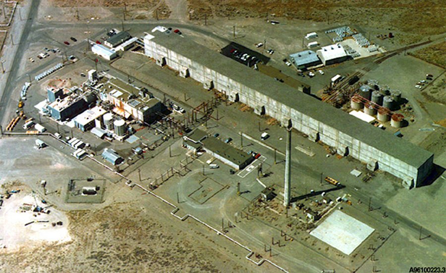
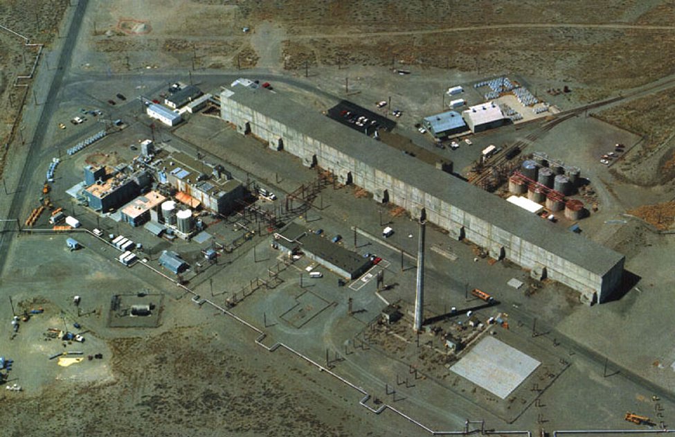
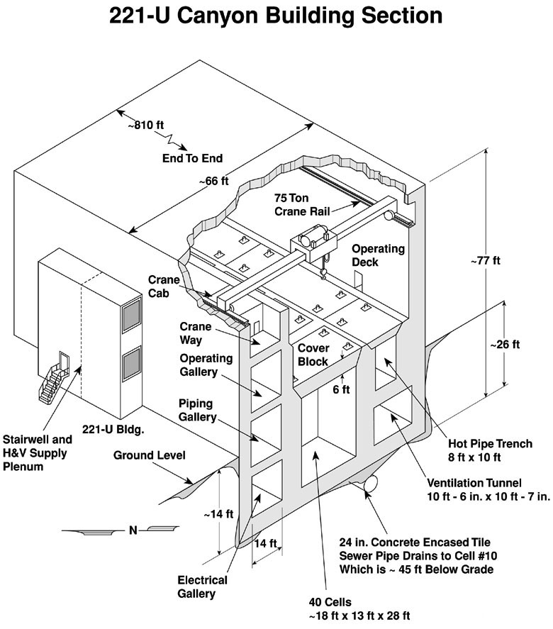
The 221-U Facility is a multi-storied building approximately 246.9 m (810 feet) in length. The building and equipment were originally designed in support of the production of plutonium. However, it was never used for this purpose. After construction, it was remodeled and used for the recovery of uranium from tank farm wastes. The foundation is constructed of reinforced concrete varying from 1.8 to 2.4 m (6 to 8 feet) thick. The outside walls are reinforced concrete varying from 0.9 m (3 feet) to 1.5 m (5 feet) thick. It has a concrete roof varying in thickness from 0.9 m (3 feet) to 1.2 m (4 feet) thick. The building is divided into two main portions by a concrete wall 1.5 m to 2.7 m thick (5 to 9 feet) thick running the full length of the building. One portion is called the canyon, and the other is called the galleries. The length of the building is divided into twenty sections, at approximately 12.2 m (40 feet) intervals.
This building is not being used for any processing activities. However, the cells and canyon deck are being used for storage of contaminated process equipment. The 30,000-cfm ventilation system is still active. Exhausting is possible through the 291-U exhaust facility by activating the electrically driven exhaust fans.
The electrical gallery (below grade) is split into two separate parts by a railroad tunnel entering the building. The clearance from the floor to the ceiling inside the gallery is approximately 4.6 m (15 feet). As the name implies, this gallery houses electrical switchgear and controls for controlling process equipment located on the canyon side of the building. The pipe gallery is also split into two separate sections by the railroad tunnel and has essentially the same dimensions as the electrical gallery. Clearance is restricted by the mass array of piping suspended from the ceiling and leading through the barricade wall into the canyon side of the building. Like the electrical gallery, there are no openings into the canyon from the pipe gallery. The operating gallery is located above the pipe gallery and is similar to the electrical and pipe galleries, but is unique in that the railroad tunnel does not divide it into two parts. It runs the full length of the building and contains instrumentation and piping manifold stations for controlling the process in the canyon. The crane gallery (crane way) is directly above the operating gallery. The crane gallery is partitioned from the canyon by a 1.5 m (5 feet) thick wall, but it has no ceiling and is open to the process canyon. There are two cranes in the canyon, both are traveling cranes and ride a common track. The main crane is a 75-ton capacity bridge crane and it has a ten-ton capacity auxiliary hoist attached. It has an 18.3 m (60 feet) span, and travels a maximum rate of 48.8 m (160 feet) per minute.
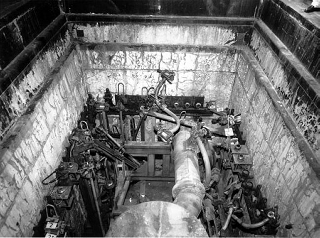
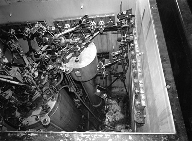
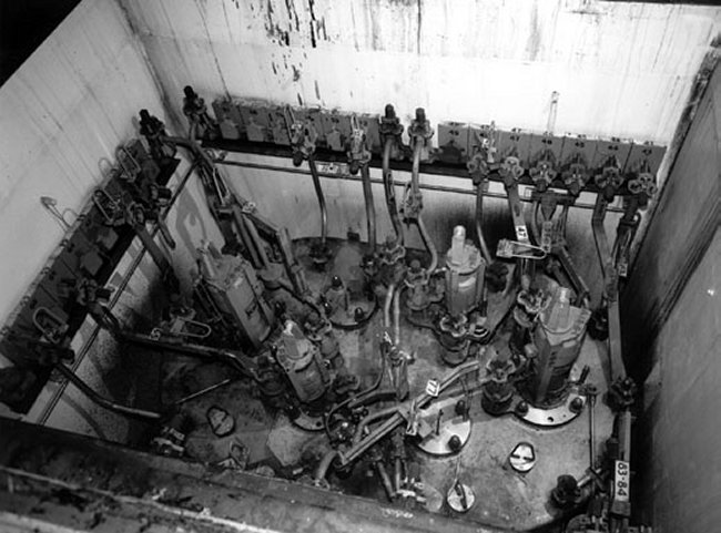
The canyon cells housed the processing equipment for feed concentration and centrifugation, solvent-extraction, waste treatment and solvent treatment. Stepped, removable 1.8 m (6 feet) thick concrete blocks cover and provide access to the cells. The canyon portion of the building is approximately 11.0 m (36 feet) wide and is divided into twenty sections. Each section is approximately 12.2 (40 feet) wide and contains two process cells. The cells contain process equipment, such as vessels, centrifuges, piping etc. The cells measure approximately 3.4 x 4.9 m (11 x 16 feet) and are 8.5 m (28 feet) deep from the top of the concrete cell covers to the bottom of the cell. Exceptions are cells in sections 1, 2 and 5. Sections 1 and 2 have slightly larger cells, and one of the two cells in section 5 (cell 10) is designed to accumulate water in the canyon. This cell is 14.3 m (47 feet) deep. All cells and the pipe trench drained to this cell via a 61 cm (24 inch) concrete-encased tile sewer pipe. Stepped, removable concrete blocks cover the cells.
The tops of the cell covers form the deck of the canyon. The deck is level with the floor of the operating gallery. Height from the deck to the ceiling is approximately 12.2 m (40 feet). The canyon deck is a regulated work zone. Entrance into the canyon is possible through air-lock doors at ground level located at each of the odd-numbered sections. These entrances are at the deck level.
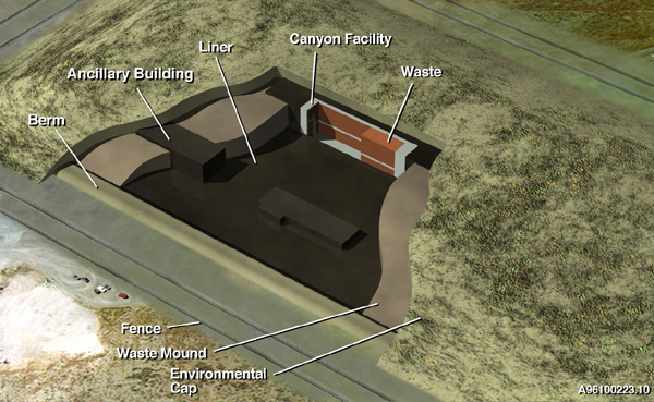
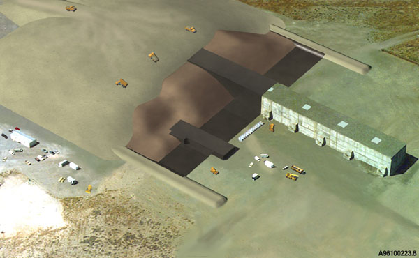
The Canyon Disposition Initiative (CDI) Project is a collaborative project that includes participation across the DOE Office of Environmental Management (EM). The CDI Project is evaluating the feasibility of using the five chemical processing facilities (canyons) as assets for disposal of low-level wastes, instead of a mortgage liability to the Environmental Restoration (ER) Program. The U Plant facility is being used as a pilot for this evaluation.

|
NEWSLETTER
|
| Join the GlobalSecurity.org mailing list |
|
|
|