

IMPROVED - ADVANCED CRYSTAL / IKON / "KH-12"
RECONNAISSANCE IMAGING SPACECRAFTBy © Charles P. Vick 2007 All Rights Reserved
04-25-07
Disclaimer
The opinions and evaluations stated here in are only the author’s and cannot be construed to reflect those of any Government agency, company, institute or association. It is based on public information, circumstantial evidence, informed speculation, and declassified U.S. intelligence community documents, official US government documents and histories, oral histories, interviews and engineering analysis. As with all data regarding the intelligence programs of the US intelligence community, this analysis is subject to revision--and represents a work in progress.
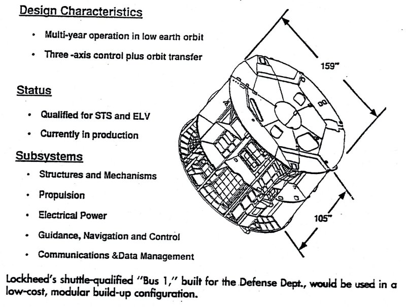
Bus-1 Systems
“Bus-1 has successfully completed all three Space Shuttle safety reviews.” “The re-boost capability, as provided by the two main engines, is single failure tolerance.” Page. 48, “The Bus-1 guidance, navigation and control are provided by an attitude reference system that senses deviations from a desired attitude and position. This information is processed within the data management system and acted on by a set of effectors. The attitude reference system contains nine rate gyros, three star sensors, two 3-axis magnetometers and nine Sun sensors. The effectors consist of six single-axis gimbaled control moment gyros, each rated at 1,700 foot-pound-seconds of angular momentum. In addition, 12 reaction control thrusters are used to assist the control moment gyros.”
“Bus-1 contains 11,660 pounds of nitrogen-tetroxide and monomethylhydrazine propellants. The propulsion system is totally contained within Bus-1 and consists of four pressurization and six propellant tanks, feeding six pairs of 14-pound thrusters and two 200 pound re-boost thrusters. The attitude control engines are positioned circumferentially around the aft end of Bus-1. …. The re-boost thrusters provide translational capacity. To prevent an inadvertent thruster firing, the propulsion system has redundant failure tolerant valve sequencing and avionics hardware. ….”
“The power system supplies an average of 2.6 kW to 1.8 kW for Bus-1 active systems and 0.8 kW for the payload. …… For power storage, six 90 amp-hour nickel-hydrogen batteries are mounted inside Bus-1. Heat pipes are used for battery thermal control.”
“The data management system is composed of primary and secondary processors, both with A and B strings providing some internal redundancy, and hardwired attitude control logic for back-up control. The command and control computer operates at 1.4 million instructions per second with 96 kilobytes of 24-bit word addressable memory. The system can store a maximum of 12,000 commands. A 100-channel serial input and output processor and a remote decoder multiplexer are also part of the data management system.”
“The communications system consists of a dual channel S-band transponder capable of l kbps on the uplink and 2 or 32 kbps for down-link, with four switch-able antennas. The system is compatible with the spacecraft ground link system used by the United States Air Force. The S-band system could be made compatible with the NASA Tracking and Data Relay Satellite System, but would then be limited to 16 kbps downlink. Primary communications are effected by a three-axis antenna pointing system located on the aft bulkhead. The current primary Bus-1 communication electronics are not suitable for high rate Ku-band Tracking and Data Relay Satellite System communications.”
“The structure is built around a central hexagonal core that acts as the primary load-carrying backbone. The six fuel tanks are located within this hexagonal core. Bulkheads and…” The Bus-1 mass is 24,954 lbs wet while its fuel mass is 11,660 lbs and the dry mass is 13,294 lbs and it has design five year active orbital life that it has exceeded. KH-11 had a dry mass of approximately 13,289 lbs and a wet SSB bus mass of 10,668 lbs. Bus-1 is some 13.25 feet (159 inches) in diameter and cylindrically 8.75 feet long (105 inches) with a total length of 13.1 feet. The Advanced Crystal orbital insertion mass is estimated to be 28,800-29,600 lbs for Titan-4A and 32,660-36,700-38,800 lbs for the Titan-4B with an estimated dry mass of 21,000-22,500 lbs. Ref. (NASA Space Station Redesign Team Final; Report), p. 48, 49, 50
Ref. (Lockheed missile & Space Company, Inc. document “Bus-1 Implementation Concept for Space Station Alpha”, 25 November 1993 pp. 48, ), Lockheed Missile & Space Company, Space Systems Division
“2.3.2 BUS 1 Subsystem Description”
“The Guidance, Navigation, and Control Subsystem consists of 6 single-axis Control moment Gyros (CMGs) for maneuver capability, control, and momentum storage capability for Space Station Alpha. Each unit provides 1700 ft-lb-sec of angular momentum capability. Nine rate gyros provide attitude reference knowledge. Five of the nine gyros are active to provide fault detection against gyro hardware (18) failures. This allows mission continuation without entrance to safe mode. Four spare gyros provide the reliability to meet the 5 year design life criteria. Three scanning star sensors provide periodic updates to the attitude reference system. These units provide star detection accuracy of < 5 arc-seconds and operate over a wide rate range accommodating all Space Station Alpha maneuvers. Ephemeris determination is accomplished by use of the BUS 1 Position Reference Subsystem which utilizes a single channel GPS receiver and ground algorithms.”
“Electrical Power Generation, Storage, and Distribution is accomplished with the highly fault tolerant Electrical Power Subsystem (EPS) integral within BUS 1. …… Six 90 amp-hour Nickel Hydrogen batteries provide storage capacity and redundancy for the 5 year design life. Two fully redundant battery charge controllers provide power routing from solar arrays or batteries to BUS 1 power users. Power distribution and control is provided by fully redundant equipment which functionally separates equipment loads, pyro activation, and motor control.”
“BUS 1 provides 11,600 pounds of nitrogen tetroxide and monomethylhydrazine propellants. The Propulsion Subsystem is fully contained within BUS 1 and consists of four re pressurization spheres and six propellant tanks, feeding six pairs of 14-pound thrusters and two 200 pound thrust re-boost engines. Two separate systems provide propulsion redundancy, and series redundant thruster valves protect against propellant leakage.”
“The Data Management Subsystem (DMS) is a fully redundant cross-strapped system capable of running BUS 1 functions along with some external utilities. The subsystem is comprised of two Computer Assemblies with a total of 1.4 million instructions per second with 176 kilobytes of 24-bit word addressable memory, two Input / Output Processors which are fully redundant and fully cross-strapped with 100 serial channels and Remote Decoder Multiplexer (RDM) interface to provide command and telemetry to all BUS 1 hardware and sensors. The three RDM’s provide 3072 instrumentation channels and 768 discreet channels for commands and analog / digital telemetry. The Telemetry and Command Unit (T&C) is a single string backup hardware for safe mode operations and S-band telemetry.”
“The BUS 1 Structure (Figure 2.3.2-2) is built around a central hexagonal core that acts as the primary load-carrying backbone. The six propellant tanks are located within this hexagonal core. Bulkheads and transverse partitions are placed around this core, creating bays for equipment installation. Three longeron trunnions and one keel trunnion are located on the periphery for ground handling and launch vehicle attachment. While not specifically designed to meet micro meteoroid and space debris protection, the BUS 1 structural configuration offers more inherent shielding than most other Space Station elements.” (p. 19.)
“Thermal Control Subsystem (TCS) utilizes heat pipes and radiators to provide passive heat dissipation for the battery assembly. External surfaces are protected using multi layer insulation, tapes, and paint patterns tailored to ………………………….LVLH flight mode and inclination.”
“Communications consists of a dual channel S-band transponder capable of IKbps uplink and 2 or 32 Kbps downlink, with four switch-able antennas. The subsystem is compatible with the Space Ground Link System (SGLS) used by the United States Air Force.”
“Safe Mode consists of single string hardware capable of providing independent attitude control/reference, data handling / communications, and thruster commanding. The Attitude Control Electronics (ACE) provides hardwired command generation and fault detection logic. The Telemetry and Command Unit (T&C) provides independent data handling and S-band communications. Attitude reference ISS provided by the Three Axis Gyro Assembly (TAGA), Magnetometers, and Sun Sensors. The ACE) provides thruster commands to Propulsion Interface Unit (PIU).” Ref. (p. 20)
“3.6.4 Refueling Ref. (p. 64)
“The existing BUS 1 vehicle utilizes a hypergolic bipropellant propulsion system. The propellants are monomethylhydrazine (MMH) and Nitrogen Tetroxide (NTO). The system utilizes a blow-down capability (370 - 140 psia) with a single stage re pressurization capability using pyrotechnic valves. Total stored propellant capability with the six tank configuration is 11,660 Ibm, with a delivered impulse of greater than 3,000,000 Ibf-sec. The re pressunzation system has a maximum design pressure of 3600 psia. The maximum design pressure of the propellant storage tanks is 370 psia. The propellant tanks and the majority of the propulsion system plumbing, is manufactured from titanium. The tanks utilize a surface tension propellant management assembly. The system is outfitted with two Orbit Adjust Thrusters (OATs) and two sets of six Reaction Control Thrusters (RCTs), with thrust ranges of 300-140 Ibf and 22-10 Ibf, respectively, over the blow-down range. The OATs are certified for 3,000,000 Ibf-sec total impulse with a steady state specific impulse of 295 Ibf-sec/lbm, and 95 engine thermal cycles. The RCTs are certified for 134,000 Ibf-sec of total impulse, with a pulse mode specific impulse of 265 Ibf-sec/lbm, and 62,500 pulse life. Feed system manifold is designed to provide one failure tolerance for propellant supply and the thrust functions. Propellant isolation valves provide the third barrier to bulk propellant leakage, cross strap capability between independent feed manifolds, and back pressure relief of these manifolds. Dual seat thruster valves are provided on the OATs and RCTs for two barrier protection to propellant leakage. Control and monitoring of the propulsion system is provided by the redundant Propulsion Interface Unit (PIU).”
Ref. (unclassified Lockheed missile & Space Company, Inc. document “Bus-1 Implementation Concept for Space Station Alpha”, 25 November 1993 ), Lockheed missile & Space Company, Inc.)
What has become apparent is that the Bus-1 derivation flown on the advanced Crystal was originally designed to fly on but never was flown on Shuttle except for Misty-1 but was always flown on the Titan-4A and Titan-4B within the Titan Payload Adapter (TPA) bucket barrel since it was originally designed to fly on shuttle but was later transferred to Titan-4A, 4B with considerable effort.
This is in addition to the primary offset folding imaging equipment utilizing the front viewing apparatus that utilize a black painted louver photo window that works very similar to the way modern SLR camera’s work today for nuclear and laser battle hardening and not a old KH-11, KENNON, Hubble telescope type flip back nose lid. The so called Advanced Crystal spacecraft utilized some flat Black, silver foil lines with gold and silver foil trim which lights up like a light bulb in the sky under normal solar lighting.
The top, side bays for the decoy sub satellites can be seen in the Bus-1 literature along with it navigation star trackers and attitude control thruster racks (Ref. NASA Space Station Redesign Team Final; Report), (Ref. Boeing Historian Office provided unclassified Lockheed document “Bus-1 Implementation Concept for Space Station Alpha”). The two main thrust chambers of the Bus-1 module are also prominently displayed. All of the Advanced Crystal satellite buses carry deployable decoys and mission specific packages. It almost certainly carries Passive – store dump SIGINT – COMINT packages in addition to communication dishes both for satellite to satellite and up, down links.
Lockheed Martin is the lead systems integrator under the NRO’s lead design bureau specifications configuration control requirements. Lockheed is the body hugging curved solar array vendor as seen in the Lockheed solar array vendor document (Ref. Lockheed Missile & Space Company Solar Arrays – Fact sheets 10-85) and from both the President G. W. Bush (Senior) NARA Presidential Library Crystal RECSAT model display. The Solar arrays are made of battle hardened Gallium Arsenate. The off set telescope is a Lockheed, Perkin-Elmer Corporation design verses the suggest imagery telescope optics designer used on the KH-11 KENNON, and Hubble telescope design heritage.
There are the usual Navigation, orientation, horizon and sun sensors of Lockheed utilized that can be seen in Lockheed Vendor documents (Ref. Lockheed Missile & Space Company Fact Sheet, Earth/Horizon Sensors1-90, & Ball Aerospace & Technology Corp. Space News advertisement).
|
NEWSLETTER
|
| Join the GlobalSecurity.org mailing list |
|
|
|