

Chapter 9
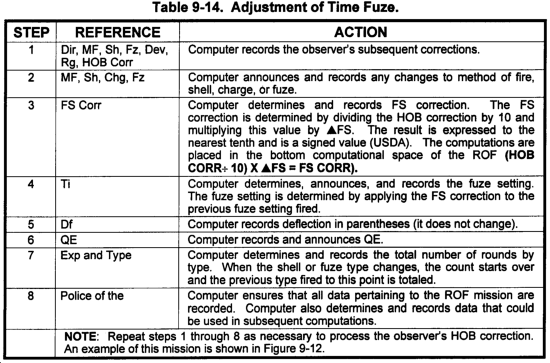
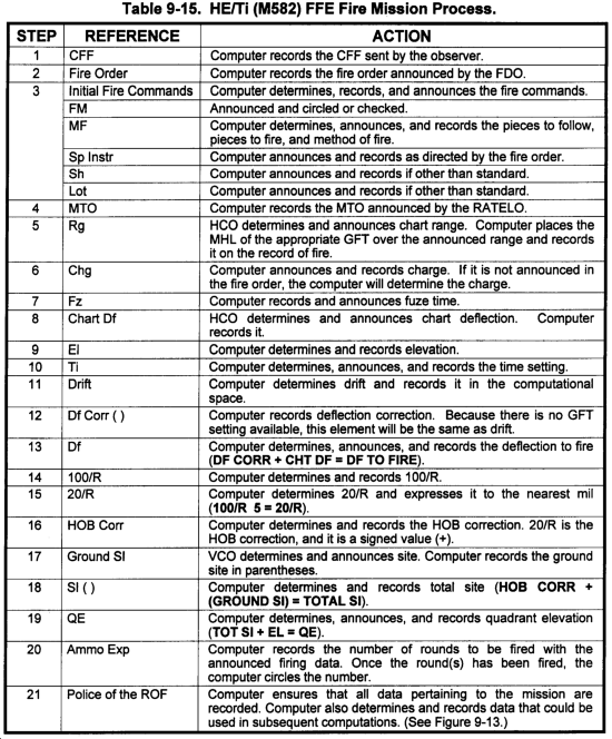
FIRE MISSION PROCESSING
In the battery or platoon FDC, all actions are oriented toward timely and accurate fire mission processing. All actions must provide the best possible flow of information between FDC personnel. The battery or platoon FDC must be trained to determine responsive and accurate firing data. Upon receipt of a call for fire, FDC personnel must work as a team to accomplish many tasks at the same time. (See Figure 9-1.)

Section I
Duties and the Record of Fire
| This section implements STANAG 2934 and QSTAG 225. |
Understanding the duties within the FDC is imperative. All activity supports the computer. He determines and records firing data on the record of fire. He is also the link to the howitzers, because he transmits the fire commands.
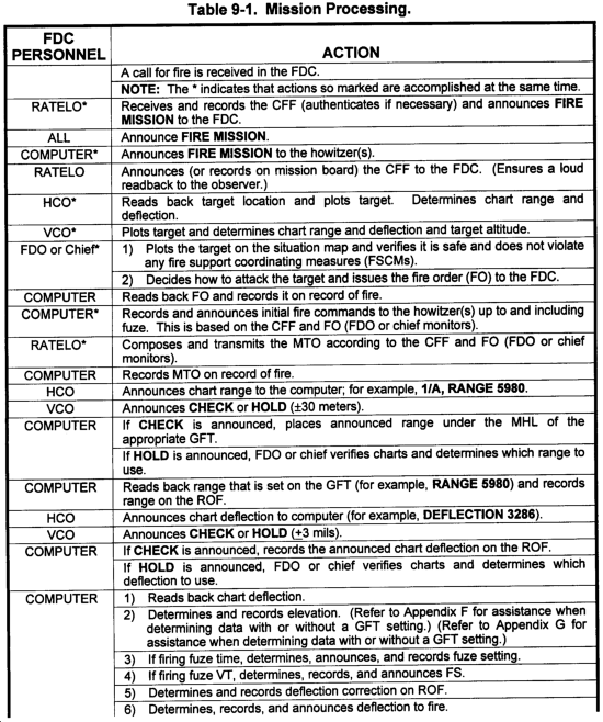
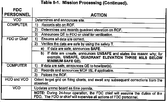
9-1. Crew Duties for the FDC
The procedures in Table 9-1 should be used to facilitate mission processing and ensure responsiveness. (For automated FDC crew duties, see Appendix F.)
9-2. Elements of Firing Data
The data determined from the firing chart must be converted to firing data that can be placed on the weapon and ammunition. These data consist of the charge, fuze setting (when applicable), deflection, and quadrant elevation to be fired.
a. Shell. Shell is the projectile to be fired. The projectile will have a direct impact on determining the remaining elements since firing tables are based on the projectile.
b. Charge. The amount of propellant to be fired with artillery ammunition is varied by the number of propellant increments. The charge selected is based on the range to the target and the tactical situation.
c. Fuze. Fuze is the fuze to be fired. The fuze will have a direct impact on determining the quadrant elevation when firing mechanical time fuzes.
d. Fuze Setting. When a projectile with a mechanical time or proximity fuze is fired, the computer determines a fuze setting to be set on the fuze that should cause it to function at the desired point along the trajectory. Fuze setting is a function of elevation. This fuze setting is determined from the TFT or GFT. Some projectiles may also be fired with a point-detonating fuze, which can be set for delay action.
e. Deflection. The deflection to fire is the deflection announced to the howitzer. To compute deflection to fire, apply the deflection correction to the announced chart deflection by using the LARS rule (left, add; right, subtract). Determine the deflection correction by adding the GFT deflection correction to the drift corresponding to the initial elevation. (GFT deflection correction is discussed in Chapter 10.)
f. Quadrant Elevation. Quadrant elevation is the algebraic sum of site and the angle of elevation. Quadrant elevation is the angle through which the tube of the howitzer must be elevated from the base of the trajectory to cause the trajectory to pass through the target.
(1) Elevation. The angle of elevation is the vertical angle between the base of the trajectory and the axis of the bore required for a projectile to achieve a prescribed range under standard conditions.
(2) Site. If the target and the howitzer are not at the same altitude, site will be determined. Site is combined with elevation to cause the trajectory to pass through the target. If the target and howitzer are at the same altitude, site is announced as zero.
9-3. Recording Firing Data
a. DA Form 4504 (Record of Fire) is a legal document used for determining and recording firing data. It is organized to allow a smooth flow in determining and processing afire mission. It is used for the following:
- Recording the call for fire.
- Computing and recording firing data for all types of fire missions.
- Keeping a permanent record of a fire mission, to include the type and amount of ammo expended during the mission.
b. On DA Form 4504 (Figure 9-2), the heavy black lines indicate major sections of the form. Shaded portions denote items that must be announced to the howitzer sections. The use of each block on the record of fire is explained below.

(1) Call for fire block. The CFF announced by the observer is recorded in this block. (See Figure 9-3.) Table 9-2 explains each item and its use.

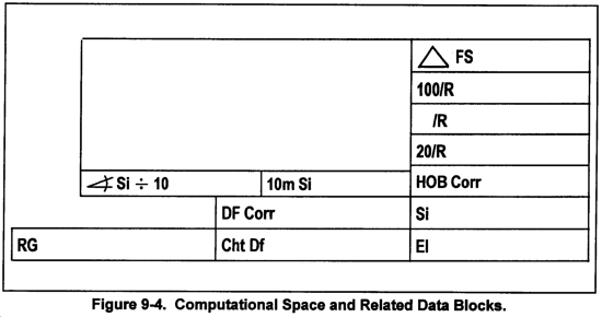
(2) Computational space and related data blocks. These blocks are used to compute and record data used in determining firing data. (See Figure 9-4.) Table 9-3 explains each item and its use.

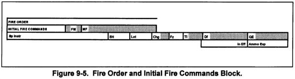
(3) Fire order and initial fire commands block. The fire order announced by the FDO and the initial fire commands transmitted to the howitzers are recorded in this block. (See Figure 9-5.) Table 9-4 explains each item and its use.
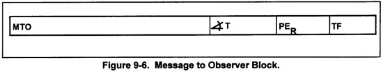
(4) Message to observer block. The message to observer, angle T, probable error in range, and time of flight are recorded in this block. (See Figure 9-6.) Data determined but not sent are recorded in parentheses. Table 9-5 explains each item and its use.
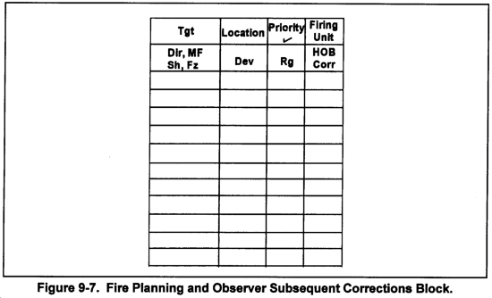
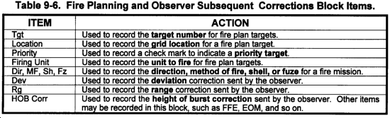
(5) Fire planning and observer subsequent corrections block. Fire plans or subsequent corrections transmitted by the observer are recorded in this block. (See Figure 9-7.) Table 9-6 explains each item and its use.
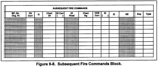
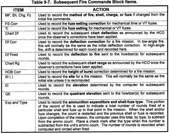
(6) Subsequent fire commands block. Fire commands are recorded in this block. (See Figure 9-8.) Data placed in parentheses indicate data that were determined but not sent because of no change. Table 9-7 explains each item and its use.
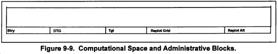
(7) Computational space and administrative blocks. These are the lower computational areas used to record required data or conduct computations. (See Figure 9-9.) Table 9-8 explains each item and its use.
Section II
HIGH EXPLOSIVES
The HE projectile is the base round for the HE family of projectiles. The HE projectile is available in all cannon weapon systems (105 mm, 155 mm). The HE ballistic family includes the antipersonnel improved conventional munitions, illumination, chemical, and smoke.
9-4. Overview
a. HE projectiles are hollow steel cases filled with explosives (trinitrotoluene [TNT] or composition B). They can be fuzed for air, surface, or subsurface burst. HE projectiles are used against personnel and material objects because of blast and fragmentation effects.
b. Determination of firing data for a point-detonating (Q), mechanical time super quick, time, or variable time fuze mated to an HE projectile is almost identical. Only minor procedural differences exist. Data are determined from the GFT, GST, and TFT.
c. The HE-quick shell-tie combination is the ammunition used for the basic fire mission. Chart data are determined to the target. The computer determines data with the GFT. The procedures for computing data without a GFT setting areas outlined in Table 9-9.
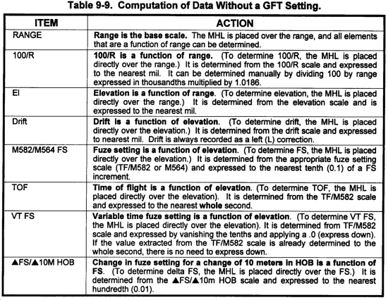
NOTE: Under normal circumstances, FDC personnel will be able to determine a GFT setting. The determination and explanation of a GFT setting is covered in Chapter 10. When a GFT setting is applied, certain elements of data will be determined as described below.
|
| NOTE: The fire order SOP and fire command standards in Figure 9-10 are used for all the examples found in this chapter. |

9-5. Examples of Completing the Record of Fire for HE Fire Missions
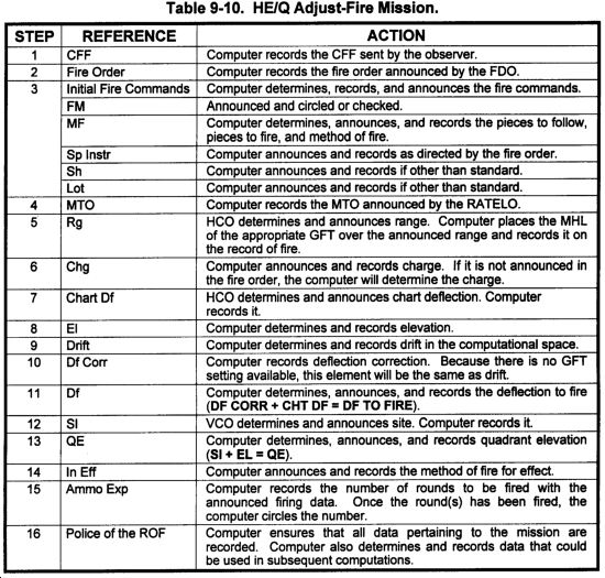
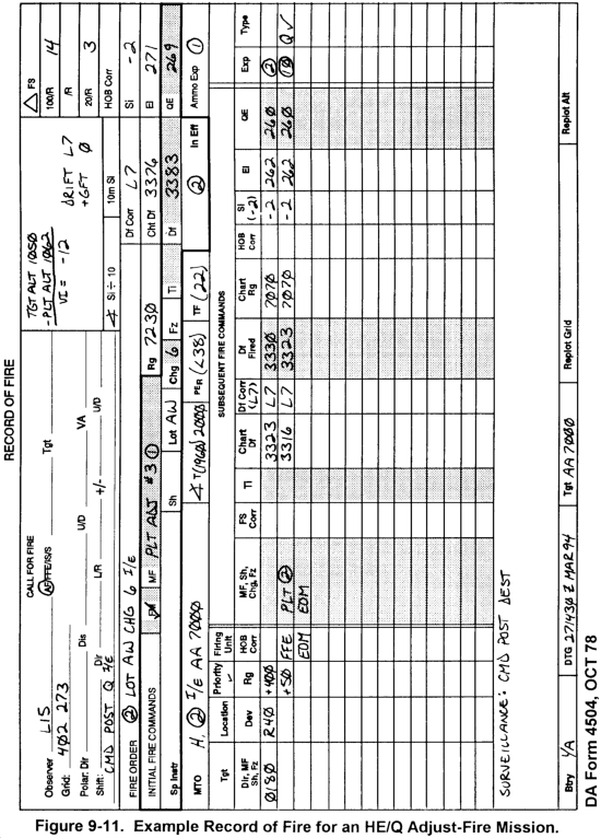
a. HE/Q Adjust-Fire Mission. Use the steps in Table 9-10 to process an HE/Q adjust-fire mission. Figure 9-11 shows an example ROF for this type of mission.
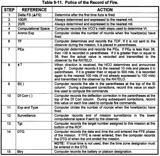
b. Police of Record of Fire. Use the steps in Table 9-11 to police the record of fire.
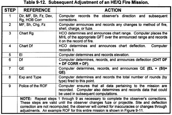
c. HE/Q Fire Mission. Use the steps in Table 9-12 for a subsequent adjustment of an HE/Q fire mission. An example ROF for this entire mission is shown in Figure 9-11.
d. High-explosive With Mechanical Time (M582).
(1) Determining data for an HE/ti round is exactly the same as HE/Q except for the HOB correction and the fuze setting correction.
(2) A time fuze achieves the best effects on the target when it functions at a 20-meter HOB. To achieve the 20-meter HOB, the trajectory of the projectile must be altered to cause the projectile to pass 20 meters above the target. By applying the mil-relation formula in a vertical plane, the amount of mils the trajectory needs to be altered at any range is 20/R. When the value of 20/R is used as the HOB correction, it will always be a positive value. The HOB correction is included in the computation of QE. The HOB correction is added to the site (ground site), and a total site is determined. This total site is applied to elevation to determine QE. The HOB correction is applied only to the initial time QE.
(3) If subsequent adjustments for the HOB are necessary, then the FS is the only element of firing data that is recomputed. Deflection and QE will remain the same. A FS correction will be applied to the previous fuze setting. The FS correction will be a multiple of  FS/10M HOB. The FS moves the functioning of the fuze along the trajectory by increments of 10 meters. The observer will adjust the HOB by transmitting HOB corrections (up or down) to the nearest 5 meters. The observer's corrections in meters must be converted to corrections in FS. The observer's HOB correction is divided by 10 and then multiplied by FS/l0M HOB. This value is expressed to the nearest tenth (0.1) of a FS increment. Before this can be applied as a FS correction, it must have a sign (±). The sign is based on the direction (up or down) of the observer's correction. If the correction is up, then the fuze functioned late and the FS correction must be subtracted. If the correction is down, then the fuze functioned early and the FS correction must be added. Simply stated, for an up correction, the FS correction is negative; for a down correction, the FS correction is positive. An easy rule to remember is USDA (up, subtract; down, add).
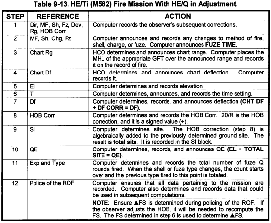
e. HE/Ti (M582) Fire Mission With HE/Q in Adjustment.
(1) Process the HE/Q adjustment as outlined in paragraph 9-5. Once the observer has requested a change in fuze type to a mechanical time fuze, process the request as described in Table 9-13. Figure 9-12 shows an example ROF for this type of mission.
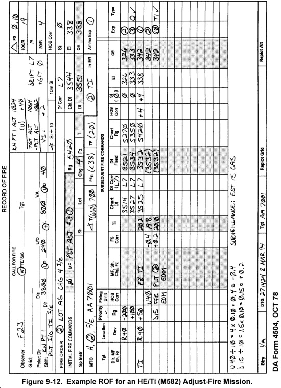
(2) If a 20-meter HOB was not achieved, the fuze setting must be adjusted. At this point in the mission, the observer does not make any range or deviation corrections. The only corrections are for HOB. Therefore, the only firing data that will change are the fuze setting. Use the steps in Table 9-14 to adjust the fuze setting, Figure 9-12 shows an example ROF for this type of mission.
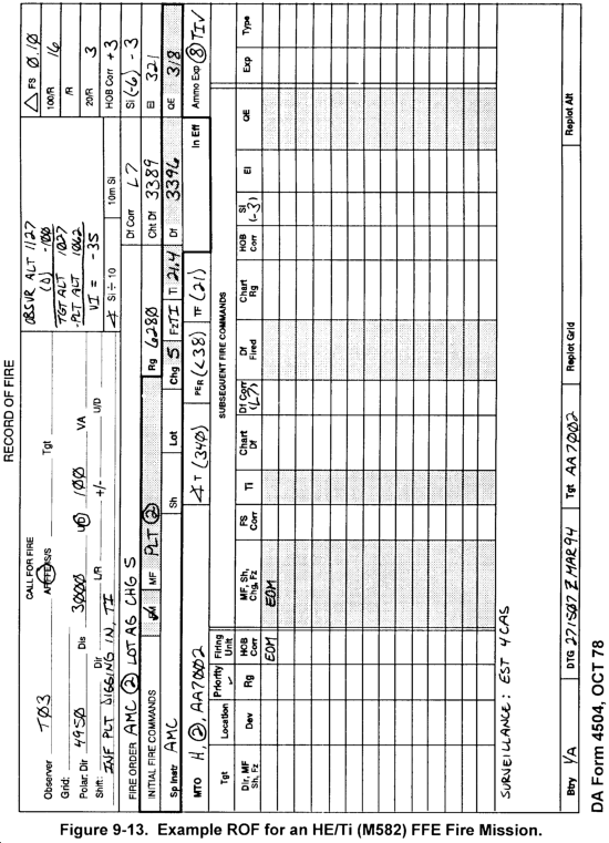
f. HE/Ti (M582) FFE Mission. Use Table 9-15 for processing an HE/Ti (M582) FFE fire mission. Figure 9-13 shows an example ROF for this type of mission.
g. High-Explosive With Variable Time (M732/M728).
(1) The variable time, or proximity fuze, is designed to function at a predetermined HOB (7 meters for M728/732). No HOB correction is needed because of the low HOB. The VT has a built-in radio transmitter-receiver. The fuze transmits a signal. When the reflected signal reaches a certain strength, the fuze will function.
(2) The VT fuze setting is determined from the time of flight of the projectile. The TOF is determined to the nearest tenth of a second (0.1). However, a VT fuze cannot physically be set to the nearest tenth. The scales are graduated in whole seconds; therefore, the TOF must be expressed down to the whole second. If the TOF extracted is already determined to the whole second, there is no need to express down. The VT memory aid "vanish tenths" will help you understand the determination of the VT FS. Expressing down provides a greater assurance of an airburst. About 3 seconds before the fuze is set, the fuze is armed and the radio transmitter is activated. Whenever a VT FS is determined, recorded, or announced, it will always end in point zero.
| NOTE: If the observer transmits a graze repeat, the automatic correction to the VT FS is to subtract 1.0 seconds. |
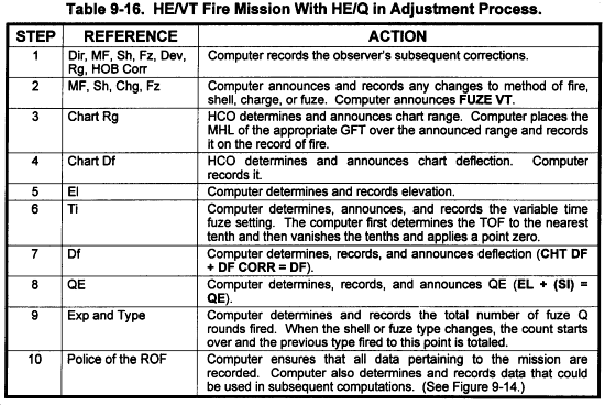
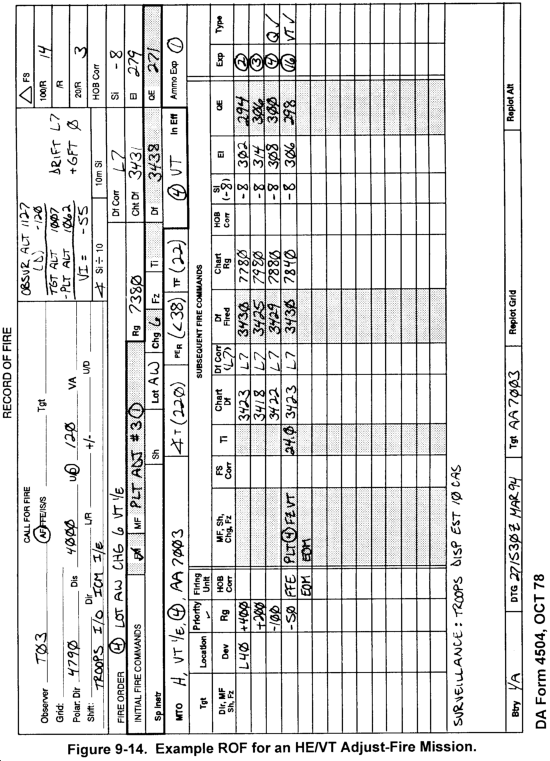
h. HE/VT Fire Mission With HE/Q in Adjustment. Process the HE/Q adjustment as outlined in paragraph 9-5. Once the observer has requested a change in fuze type to a variable time fire, process the request as described in Table 9-16. Figure 9-14 shows an example ROF for this type of mission.
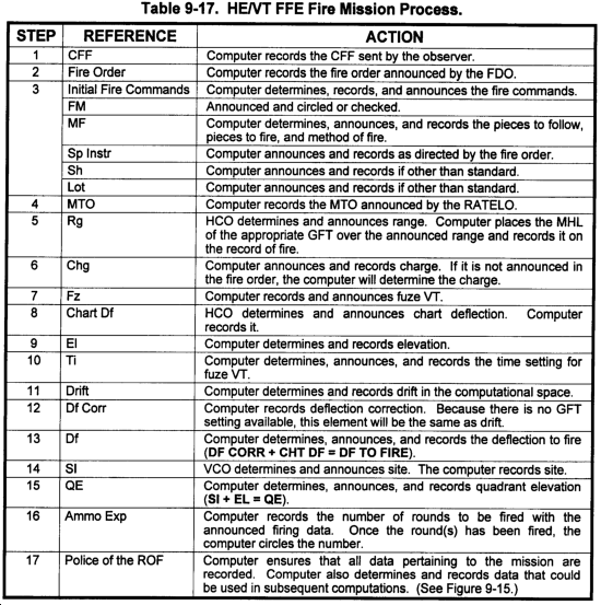
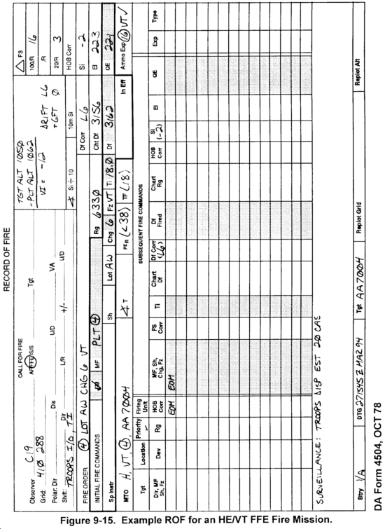
i. HE/VT FFE Fire Mission. Use Table 9-17 for processing an HE/VT FFE fire mission. Figure 9-15 shows an example ROF for this type of mission.
9-6. Example of Completing the Record of Fire for a Nonstandard Square Weight WP or HE Projectile
a. Several projectiles require corrections to firing data because of variations in square weight. The determination of firing data incorporates the use of the GFT and the TFT. The basic HE mission procedures must be altered to compensate for a deviation from the standard square weight from which the firing tables were developed. The TFTs have tables that correct for nonstandard conditions, one of which is weight. The computer must enter the appropriate TFT with the chart range to the target and the difference in square weight (increase or decrease). The difference in weight is determined by subtracting the standard square weight (or registration square weight) from the actual square weight of the projectile to be fired. The range correction factor is extracted and multiplied by the change in square weight. The result is expressed to the nearest 10 meters and is a signed value (±). This value is algebraically added to the chart range. This new range is known as the adjusted range and is used to compute elevation and all elements that are a function of elevation. The following steps apply to nonstandard square weight WP and HE projectiles.
| NOTE: Normal HE procedures are followed until the observer requests the nonstandard square weight projectile. |
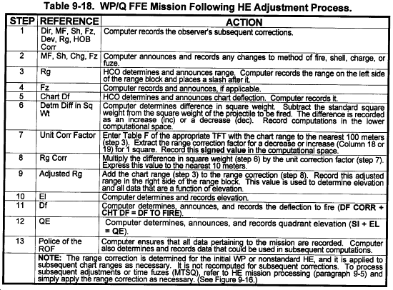
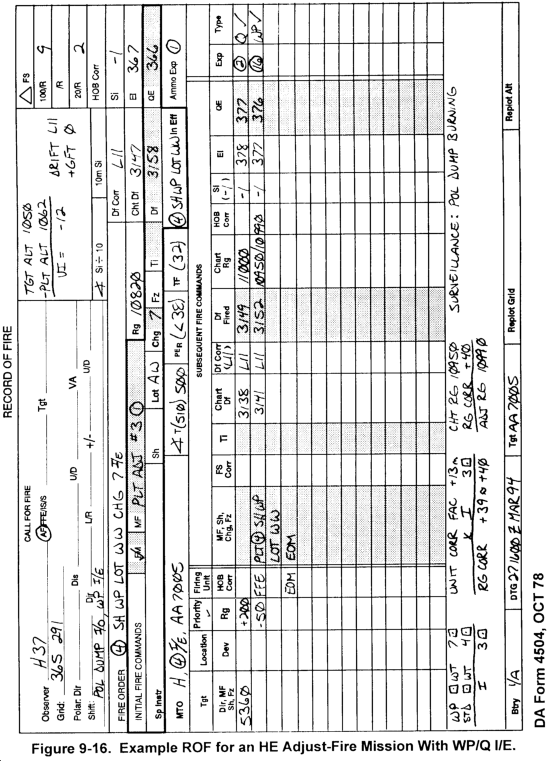
b. Table 9-18 lists the procedures for processing a WP/Q FFE mission following HE adjustment. Figure 9-16 shows an example ROF for this type of mission.
Section III
High-Angle Fire
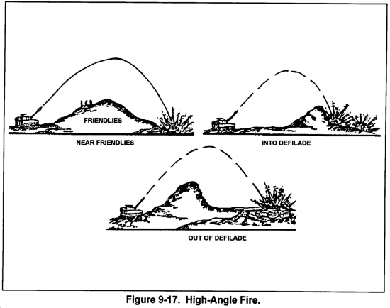
High-angle fire is used for firing into or out of deep defilade such as that found in heavily wooded, mountainous, and urban areas. It is also used to fire over high terrain features near friendly troops (Figure 9-17). The observer may request high-angle fire on the basis of terrain in the target area. The FDO also may order high-angle fire on the basis of a terrain analysis from the firing unit position to the target area. The primary characteristic of high-angle fire is that an increase in elevation causes a decrease in range.
Because high-angle fire involves large quadrant elevations and long times of flight, it will not be as responsive as low-angle fire to the immediate needs of a maneuver force. Trajectories are vulnerable to enemy detection. The long time of flight makes it difficult for the observer to identify his round, and corrections may change drastically from round to round. To help the observer, FDC personnel will announce SPLASH 5 seconds before each round impacts. To further help the observer, the FDC announces time of flight in the MTO.
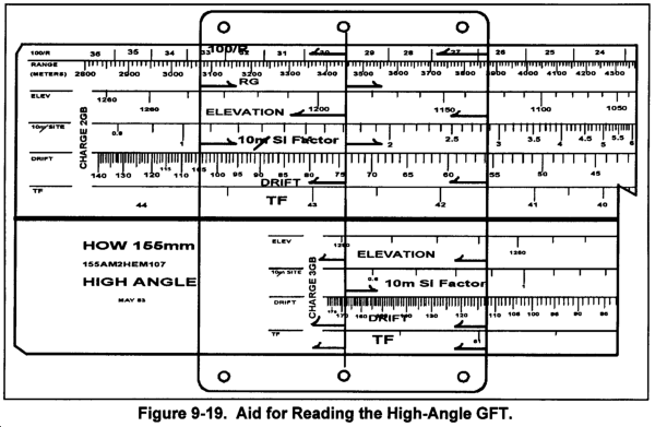
9-8. High-Angle GFT
The high-angle GFT (Figure 9-18) consists of one rule with ballistic data for multiple charges on each side. The scales on the high-angle GFT from top to bottom are as follows:
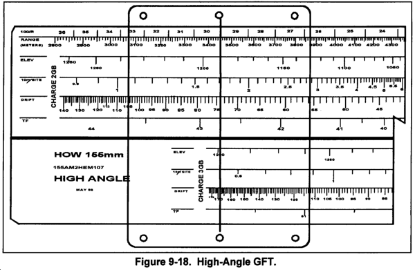
a. 100/R. This scale shows the number of mils needed to move the burst 100 meters laterally or vertically. The scale increases from right to left and is read to the nearest mil.
b. Range. This scale is expressed logarithmically in meters and applies to all charges appearing on that side of the GFT. Range increases from left to right and is read to the nearest 10 meters.
c. Elevation. This scale is expressed in mils and increases from right to left. It is interpolated to the nearest mil.
d. 10-m Site Factor. The values on this scale denote the site for each 10 mils angle of site. The numbers are printed in red and are negative values. The scale increases from left to right and is visually interpolated to the nearest tenth (0.1) of a mil.
e. Drift. The values on this scale are in mils. The scale increases from right to left and is interpolated to the nearest mil.
f. TF. This scale is graduated in seconds and is used to determine both time of flight (to the nearest whole second) and VT fuze setting. The TF scale increases from right to left.
| NOTE: Figure 9-19 shows an aid that can be used when reading the high-angle GFT. |
9-8. Duties of Personnel in High-Angle Fire
a. Except for differences noted in this section, the procedures for high-angle fire are the same as low-angle fire. Duties of FDC personnel in high-angle fire differ in several ways as described below.
b. The FDO does the following:
(1) Includes the command HIGH ANGLE in his fire order.
(2) Considers high-angle fire characteristics in selecting the shell and fuze to fire.
(a) Antipersonnel improved conventional munitions (APICM) and DPICM can be used in high-angle fire for the same types of targets as in low-angle fire.
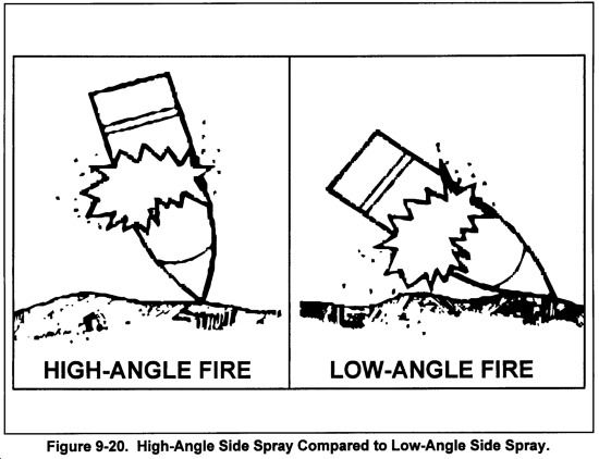
(b) The high-angle trajectory has two inherent characteristics that affect munitions selection: a steep angle of fall and large probable errors. The steep angle of fall means the projectile is almost vertical as it approaches the ground. When the HE projectile bursts, the side spray contains most of the fragmentation. Since the projectile is nearly vertical, side spray is in all directions and nearly parallel to the ground (Figure 9-20). Thus, shell HE with fuze quick or fuze VT is very effective when fired high angle. The large probable error in height of burst makes the use of MTSQ time fuzes impractical in high-angle fire.
c. The VCO computes and announces angle of site rather than site.
d. The computer does the following:
(1) Selects the charge to be fired (if it is not announced in the fire order). High-angle fire has two characteristics that affect the selection of charge: a shorter range span for each charge and a range overlap between charges. The range span within which accurate fire can be delivered by a particular charge is less for high-angle fire than for low-angle fire. This may cause a problem during a high-angle fire mission, because a large observer correction may move the round outside the capabilities of the initial charge fired. This, in turn, will necessitate changing charges. Changing charges in a high-angle fire mission is sometimes unavoidable, although it is not desirable. For this reason, the computer initially selects the charge that is least likely to require changing. As a guideline, he selects the lowest charge that allows for a range shift of at least 500 meters short of and 500 meters beyond the initial chart range.
(2) Includes drift correction. Drift is appreciably greater in high-angle fire than in low-angle fire. Because drift changes a great amount for a relatively small elevation change, the computer determines drift (recorded as the deflection correction) for each elevation. The correction is always applied to the left. If a GFT setting is available for the high-angle GFT, the computer will determine drift and algebraically add it to the GFT deflection correction. The sum is the deflection correction to be applied to the chart deflection.
(3) Includes site in the computation of QE unless the FDO directs otherwise. Site is included when the angle of site is large or when a high-angle registration or a mass mission is being fired. When several firing units are to mass on a target and only one firing unit is to adjust, site is computed at the initial range for each unit. Site for the nonadjusting units may be recomputed before FFE (for example, when the adjusting unit changes charge or when the adjusting unit conducted a target replot). When adjustment is required before massing and only one unit is to adjust, the unit that is most centrally located should be designated as the adjusting unit to minimize large differences in range for the nonadjusting units. If site is to be ignored, the FDO announces IGNORE SITE in the fire order. Since one of the criteria for ignoring site is a small angle of site, the FDO may have to wait for the VCO to compute and announce angle of site. In this situation, the FDO issues a fire order and later supplements it with the command IGNORE SITE.
(4) Announces HIGH ANGLE as a special instruction when sending initial fire commands to the howitzers.
(5) The RATELO announces the time of flight in the message to observer and announces SPLASH for each round.
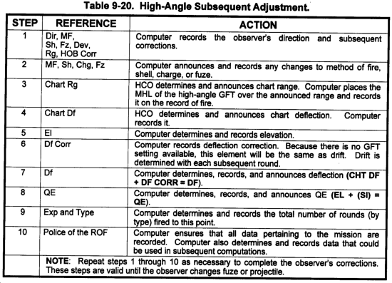
9-9. Example of Completing the ROF for an HE High-Angle Adjust-Fire Mission
a. The steps in Table 9-19 are used to process an HE high-angle adjust-fire mission. Figure 9-21 shows an example ROF for this type of mission.
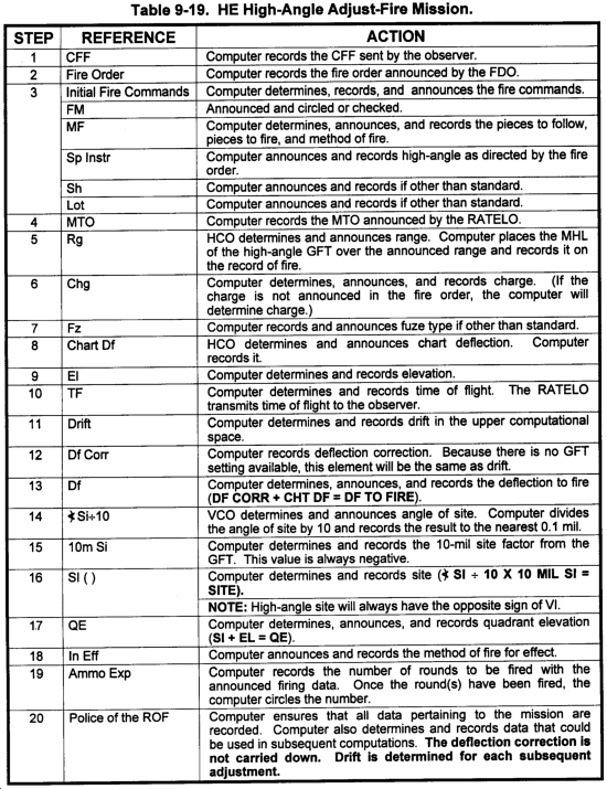
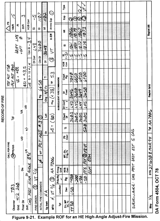
b. The steps in Table 9-20 are used to process a high-angle subsequent adjustment. An example ROF for this entire mission is shown in Figure 9-21.
Section IV
Illumination
| This section implements STANAG 2088 and QSTAG 182. |
Illuminating projectiles are available for the 105-mm and the 155-mm howitzers. They are used to illuminate a designated area for observing enemy night operations, for adjusting artillery fires at night, for marking locations, for friendly direction, or in ground/vehicular laser locator designator (G/VLLD) missions.
Illuminating projectiles are base-ejection projectiles fired with mechanical time fuzes. The filler consists of an illuminating canister and a parachute assembly. The FDO should select the lowest practical charge to prevent a malfunction caused by the parachute ripping when the flare is ejected from the projectile.
9-10. Overview
Illumination is conducted by using one of the following techniques.
a. The one-gun illumination pattern is used when effective illumination can be achieved by firing one round at a time.
b. The two-gun illumination pattern is used when an area requires more illumination than one gun can furnish. This is commonly used for aerial observers.
(1) The two-gun illumination range spread pattern is fired along the GT line. It is used when the area to be illuminated has greater depth than width.
(2) The two-gun illumination lateral spread pattern is fired perpendicular to the GT line. It is used when the area to be illuminated has greater width than depth.
c. The four-gun illumination pattern is used to illuminate a large area. Four rounds are fired at the same time by using both the lateral and range spread patterns. This is more commonly referred to as the four-gun illumination range and lateral spread.
NOTE: The decision to use the GT line or observer-target (OT) line for illumination missions should be based on unit SOP and mission, enemy, terrain, troops, and time available (METT-T). When using the OT line, the FDC will use the target grid to plot individual aimpoints. Use of the GT line may be more responsive to the observer's needs, but may not always provide the exact illumination coverage desired. The arguments for using the OT line are:
|
However, for illustrative purposes with the example fire missions, our unit SOP is to use the GT line for all illum range spreads, lateral spreads, or combination.
9-11. Illuminating Projectile GFT
a. There are two manual computational methods for the illuminating projectile. One method uses a special illuminating projectile GFT, and the other method uses Part 2 of the base HE TFT. Graphical firing tables have been developed for use with all 155-mm M485A1 and A2 illuminating projectiles and with the 105-mm M314A1 and A2 and M314A2E1 projectiles. Figure 9-22 shows a GFT for the illuminating projectile.
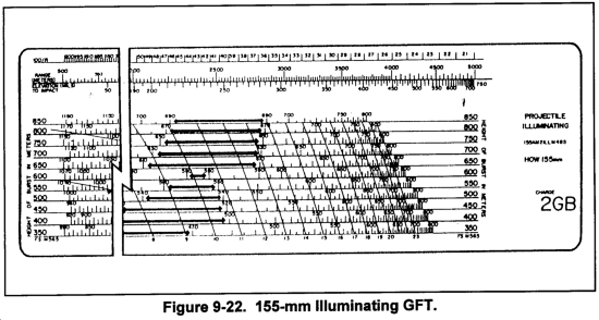
b. The scales of the illuminating GFT, from top to bottom, are described below:
(1) The 100/R scale is printed in red along the top edge of the rule. For a given range, the 100/R scale denotes the number of mils needed to shift the burst 100 meters laterally or vertically. 100/R is read to the nearest mil.
(2) The range scale is the base scale of the illuminating GFT. All other scales are plotted with reference to the range scale. Range is read to the nearest 10 meters.
(3) The elevation-to-impact scale is graduated in mils. The elevation-to-impact scale is used to determine the range (on the range scale) to which a nonfunctioning projectile will impact.
(4) The HOB scales, labeled from 350 to 850 meters, are at the left and right edge of the QE scales. The HOB scales are graduated in 50-meter increments.
(5) The QE scale shown for each listed HOB gives the QE needed to achieve that HOB at the desired range. The QE scale is graduated in mils and is visually interpolated to the nearest mil.
(6) The FS scale consists of a series of red arcs. The scale includes a red line for each whole FS increment for the M565 MT fuze. The value of each line is printed in red at the bottom of the scale. The fuze setting is read for the desired range and HOB to an accuracy of 0.1 FS increment by visual interpolation.
| NOTE: The heavy black arrows along the QE scale denote when the trajectory is near or at the summit and does not exceed by 50 meters the HOB it represents. |
9-12. Illumination Firing Data
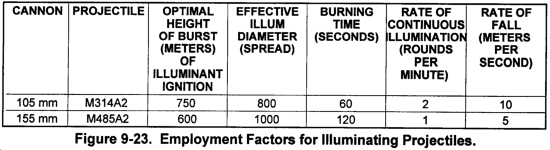
a. The illum projectile is not weight-zoned. It is designed to illuminate a large area (Figure 9-23). The minimum corrections from the observer are 200 meters for range and deviation and 50 meters for HOB. All subsequent HOB corrections are always given in multiples of 50 meters. Because of these characteristics, the determination of firing data is significantly different from HE. Drift, site, elevation, and FS are not determined. However, an illum HOB is determined. The HOB is used in conjunction with range to determine QE and FS. Therefore, any HOB correction sent by the observer will cause both the FS and QE to change.
b. The HCO determines chart data in the same manner as in an HE mission. The VCO determines VI in the same manner as in an HE mission. The computer will express the VI determined by the VCO to the nearest 50 meters.
9-13. Determination of Illumination Firing Data With the GFT
a. The appropriate HOB scale is determined by applying the VI determined by the computer to the optimum HOB for the illuminating projectile being fired. During subsequent adjustments, the observer's HOB correction is applied to the previous HOB determined.
b. QE is determined by placing the MHL over the chart range. The QE is determined by visually interpolating the point of intersection of the MHL and the appropriate HOB scale. Determine QE to the nearest mil.
c. Fuze setting is determined in the same manner as QE; that is, by placing the MHL over the chart range. Fuze setting is determined by visually interpolating between the red fuze setting arcs along the selected HOB scale. To determine the value of the arcs, follow the arcs to the bottom of the GFT. This fuze setting is for the M565 MT fuze. To determine a fuze setting for MT M577, enter Table B, Part 2, of the TFT and apply the FS correction to the MT M565 value. Determine FS to the nearest tenth.
9-14. Determination of Illumination Firing Data With the TFT
a. Part 2 of the TFT deals exclusively with illum data. Each charge has two tables, Tables A and B. Table A lists basic data, and Table B lists corrections to fuze setting.
b. FS and QE are determined by entering Table A with the chart range (expressed to the nearest 100 meters). QE is extracted from Column 2 (QUAD ELEV) and M565 FS from Column 3 (FS). These values are for the optimum HOB and must be corrected for VI.
c. HOB corrections are made in 50-meter increments. Columns 4 and 5 of Table A list the corrections to QE and FS for an increase of 50 meters in HOB. The VI is expressed to the nearest 50 meters. Once the VI is expressed, it is divided by 50 to determine the number of 50-meter increments that are needed. The number of 50-meter increments are multiplied by the value in Column 4 (QE) and Column 5 (FS). These values are applied to QE and FS. For a positive VI, the values are added; for a negative VI, the values are subtracted. These corrected values are the FS and QE that should be fired.
d. To process HOB corrections, divide the observer's HOB correction by 50. This will provide the number of 50-meter increments. Multiply the number of 50-meter increments by the values in Columns 4 and 5. Apply this correction value as described above.
e. 100/R can be determined manually by using the mil relation formula by dividing 100 by the range in thousands and multiplying that value by 1.0186. The result is expressed to the nearest mil.
| NOTE: The FS determined from the illuminating GFT or from Table A, Part 2, Column 3 of the TFT is for the M565 fuze. A correction value must be applied to determine a fuze setting for the M577 fuze. Table B of the TFT lists the correction values. To determine the correction value, enter Table B with the FS for the M565 fuze. Apply this FS correction to the FS for the M565 fuze. The resulting value is the FS for the M577 fuze. |
9-15. Processing a One-Gun Illumination Fire Mission
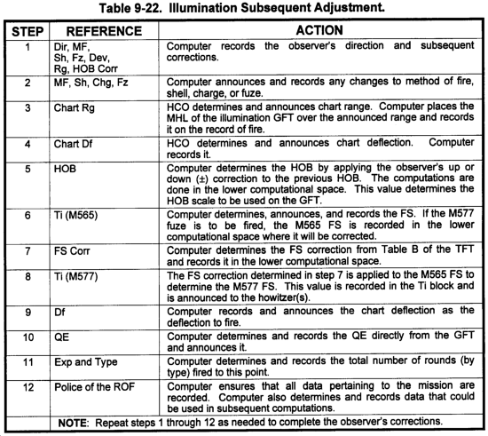
a. The steps in Table 9-21 are used to process a one-gun illum mission. Figure 9-24 shows an example ROF for this type of mission. The time fuze being fired is M577.

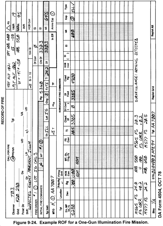
b. The steps in Table 9-22 are used to process an illumination subsequent adjustment. An example ROF for this entire mission is shown in Figure 9-24. The time fuze being fired is the M577.
9-16. Two-Gun Illumination Range Spread
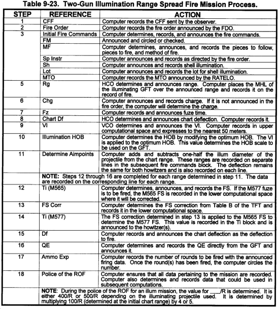
a. A two-gun range spread requires two illuminating projectiles to be fired along the GT line to provide the maximum range coverage. The projectiles are fired one effective illum diameter apart (refer to Figure 9-23). To determine the aimpoints, the computer will add and subtract one-half the illum diameter to the chart range of the aimpoint. The computer will then determine firing data at the adjusted ranges. The chart deflection will remain the same and both illumination rounds are fired with the same deflection.
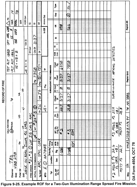
b. Use Table 9-23 to process a two-gun illumination range spread fire mission. An example ROF for this entire mission is shown in Figure 9-25. The time fuze being fired is fuze M577.
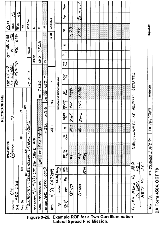
9-17. Two-Gun Illumination Lateral Spread
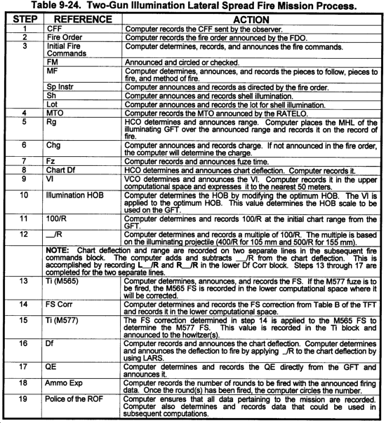
a. A two-gun lateral spread requires two illuminating projectiles to be fired perpendicular to the GT line to allow for the maximum lateral coverage. The projectiles are fired one effective illum diameter apart (refer to Figure 9-23). To determine the aimpoints, the computer must determine a multiple of 100/R (400/R for 105 mm and 500/R for 155 mm). The computer will add and subtract this value from the chart deflection to the aimpoint. The range will be the same for both projectiles. Therefore, the FS and QE for both projectiles will be the same.
b. Use Table 9-24 to process a two-gun illumination lateral spread fire mission. An example ROF for this entire mission is shown in Figure 9-26. The time fuze being fired is the M577.
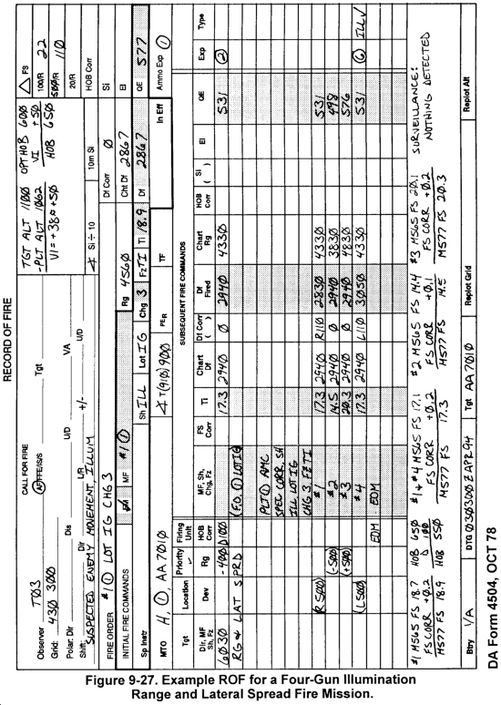
9-18. Four-Gun Illumination--Range and Lateral Spread
a. The four-gun illum pattern is used to illuminate a large area in width and depth. Four rounds are fired at the same time by using the range and lateral spread patterns. The observer may request a range and lateral spread in the initial CFF or may request this pattern during a subsequent correction as part of a one-gun or two-gun (range or lateral spread) illum mission.
b. To process a four-gun illum mission, combine the procedures for the two-gun range spread and the two-gun lateral spread illum missions. The flank howitzers will fire the two-gun lateral spread while the interior howitzers will fire the two-gun range spread.
c. If the four-gun illum mission is requested during a subsequent correction, the FDO must initiate a new fire order and the computer will announce new initial fire commands.
|
NOTE: An example ROF for this type of mission is shown in Figure 9-27. The time fuze being fired is the M577. |
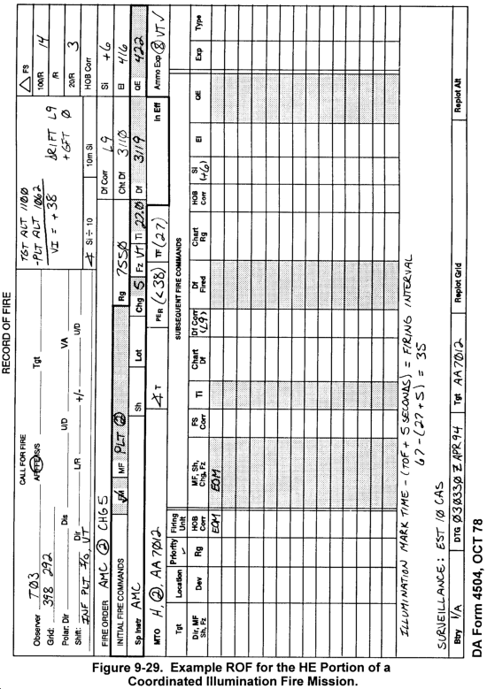
9-19. Coordinated Illumination
a. A coordinated illum mission is a combination of an illum mission (one-gun, two-gun, two-gun range or lateral spread, or four-gun range and lateral spread) and another fire mission (normally HE). The illumination is adjusted by the observer until the target is illuminated. When the best target illumination is achieved, the observer will command the FDC to MARK the illumination. Once the observer has marked the illum round, he will request coordinated illumination and transmit another call for fire. The FDC will process both missions following normal procedures. The rounds will be fired at a predetermined interval that will ensure the rounds of the second mission function when the target is best illuminated. This allows the observer to make the needed corrections and observe the effects. The firing interval may be controlled by either the FDC or observer. The preferred method is for the FDC to control the firing interval.
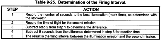
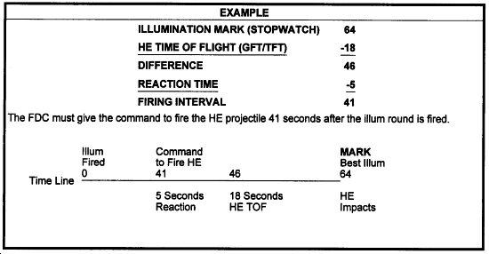
b. Every time an illum round is fired, the FDC will start a stopwatch. When the target receives the best illumination, the observer will announce ILLUMINATION MARK. The FDC will stop the stopwatch. This time interval is known as the illumination mark time and this value is recorded. When the second call for fire is received, the FDC must compute the TF for the second mission. This TF plus a five-second reaction time is subtracted from the illum mark time and the difference is the firing interval (ILLUM MARK TIME - (TF + 5 SECONDS) = FIRING INTERVAL). At this point, the FDC must ensure both missions are AMC. The FDC commands the howitzer(s) firing the illum mission to fire. The stopwatch is started as the illum mission is fired. When the firing interval is reached, the FDC commands the howitzer(s) firing the second mission to fire.
c. The observer may request by round at my command. In this situation, the observer wishes to control the firing of both missions. The FDC will compute data, ensuring both missions are AMC. The FDC must also transmit the TOF of the second mission to the observer. When the howitzers for both missions report READY, the FDC will relay this information to the observer. The observer commands the firing of the illum mission. After determining the firing interval, the observer commands the firing of the second mission at the appropriate time.
d. Use the steps in Table 9-25 to determine the firing interval. Example ROFs for this type of mission are shown in Figures 9-28 and 9-29. The illum time fuze being fired is the M577.
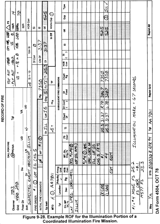
e. An example of determining the firing interval is shown below.
f. When coordinated illumination is requested, the FDO must initiate a new fire order for the second mission and the computer will announce new initial fire commands. If the howitzers that are firing the illumination are also included in the second mission, the FDC must ensure those howitzer sections understand they are firing both missions and inform them of the firing interval between missions.
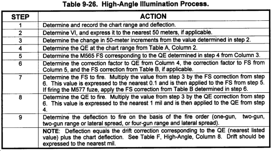
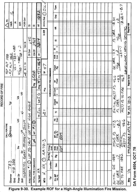
9-20. High-Angle Illumination
a. Some impact areas are so small that firing low-angle illumination severely restricts or prohibits the firing of the round because of range-to-impact concerns with the projectile body. To compensate for this, fire high-angle illumination and use the TFT (Part 2, Illumination). This is not the preferred method of firing illumination.
b. Use Table 9-26 to process a high-angle illumination mission. An example ROF for this type of mission is shown in Figure 9-30. The time fuze being fired is M577.
|
NEWSLETTER
|
| Join the GlobalSecurity.org mailing list |
|
|
|