Appendix E
REPLOT PROCEDURES
In many instances, the refinement data transmitted by the observer after the FFE phase may not reflect the actual location of the target as defined by its grid coordinates and altitude. This inaccuracy results from errors in initial target location and errors in determining the initial site fired in an adjust-fire mission. For other units to mass fires on the same point and for the observer to accurately shift from a known point located by firing, the actual target location and altitude must be determined as accurately as possible. The replot process is used for this purpose. Targets are replotted on request of the observer or when directed by the FDO. Replot gives a deflection and range with which the target location can be polar plotted from the location of the firing unit. The manual replot procedures are the same for PD and VT fuzes. The procedures for the time fuze are somewhat different.
|
NOTE: The resulting target location reflects any errors that exist in the firing data and unit location. The replot grid and altitude may differ from the survey location of the same target for this reason. |
E-1. Reasons for Replot
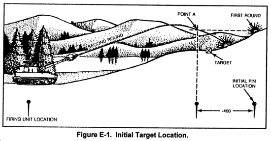
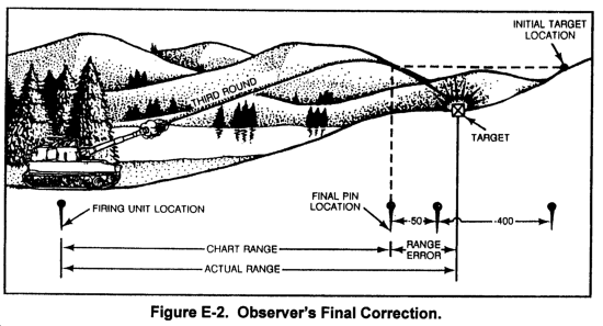
a. Inaccurate target location by the observer may result in an inaccurate altitude and an inaccurate site being determined by the FDC. For example, in Figure E-1, the observer's inaccurate target location included an altitude greater than the actual target altitude. On the basis of the inaccurate target altitude, a false site is determined and used. The observer sends a subsequent correction of DROP 400. The firing data computed reflect the data needed to cause the round to impact at Point A. Because no adjustment has been made to altitude, the projectile continues beyond Point A and impacts over the target. As shown in Figure E-2, the observer's next correction (DROP 50) results in accurate fire for effect. Figure E-2 also shows that there is a difference between the final pin location on the firing chart and the actual target location. Target replot is required to correct for this error. Replot procedures use successive approximation to determine the true site and the actual (replot) range and deflection to the target.
b. Requirements for replot are as follows:
- A map.
- Accurate refinement data from the observer.
- Valid GFT setting that accurately accounts for the nonstandard conditions existing at the time of firing.
These elements will ensure that the replot procedure is as accurate as possible. Should the GFT setting or firing chart be later corrected to more accurately reflect the conditions that existed when the mission was fired, the replot should be recomputed with the more accurate data.
E-2. Replot With PD and VT Fuzes
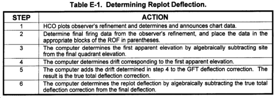
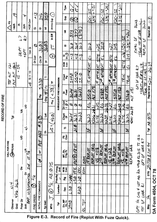
a. Replot Deflection. The replot (true) deflection to the target may or may not be the final piece deflection. Because drift may have changed during the conduct of the adjustment, determine the true total deflection correction as shown in Table E-1. (See Figure E-3.)
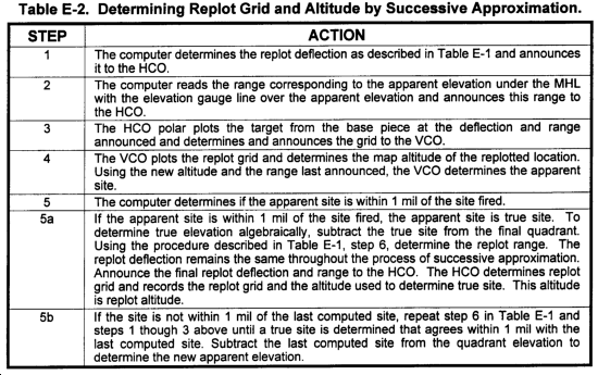
b. Replot Grid and Altitude. Determine the replot grid and altitude by successive approximation: The procedures are described in Table E-2.
E-3. Time Refinement
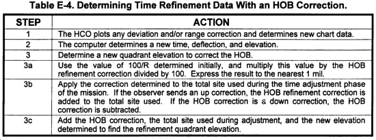
To accurately replot targets when firing fuze time, determine refinement data to correct for inaccurate HOB.
a. During the adjustment phase of the mission, the observer usually adjusts the trajectory to within 50 meters of the target before requesting FFE rounds. Upon completion of the FFE phase, the observer sends refinement data to the FDC. Elements of refinement may include deviation, range, and/or HOB. These refinement data place the mean point of the FFE bursts over the actual target location, thereby allowing the FDC to compute accurate data to the target if future fires are required. Application of refinement is a requirement for replot of targets, which allows for transfer and massing of fires.
b. Fuze time procedures are slightly different. During the time adjustment phase of the mission, the FDC applies c. Time refinement procedures without an HOB correction are shown in Table E-3.
e. Time refinement procedures with an HOB correction are shown in Table E-4.
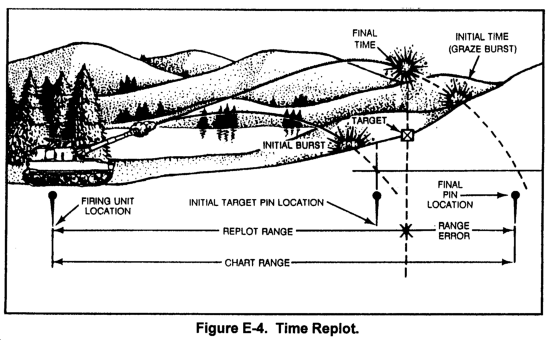
a. When a target is attacked with a mechanical time fuze, the observer adjusts the height of burst to 20 meters above the target. The final fuze setting provides an accurate representation of the target location and the altitude of a point 20 meters above the target. Consequently, when the time gauge line is placed over the final time, the range and 100/R (read under the MHL) and the elevation and drift correction (read under the elevation gauge line as a function of elevation) are true. The replot grid and altitude can then be determined (See Figure E-4.)
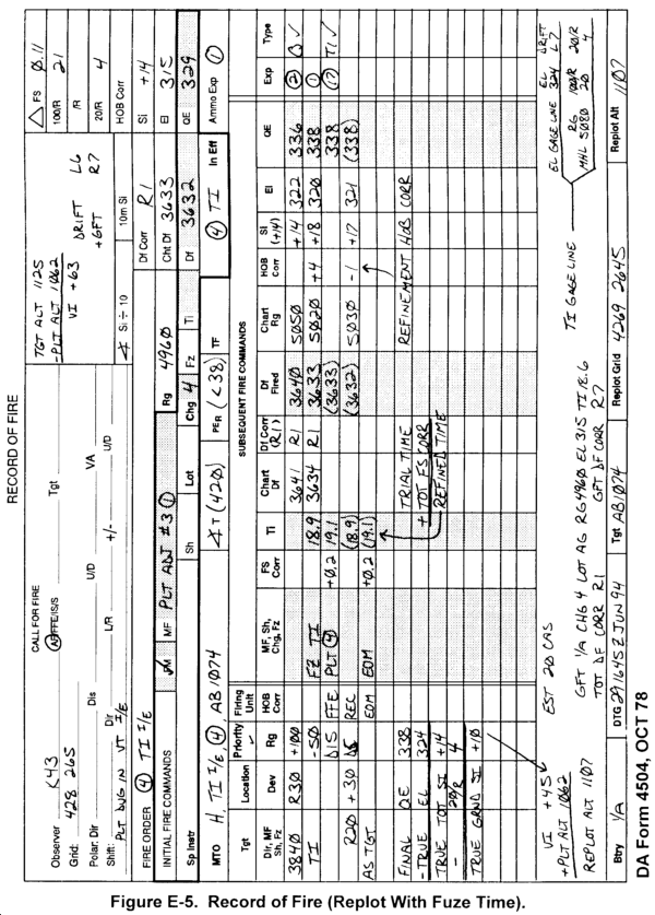
b. Replot deflection procedures are shown in Table E-5. (See Figure E-5)
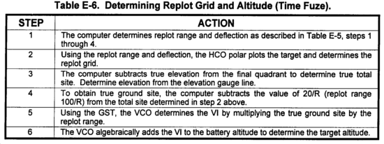
c. The procedures for determining replot grid and altitude are shown in Table E-6.
In a manual FDC or one equipped with the BCS operating autonomously, the FDO decides how to attack a target. In determining the volume of fire to place on a target, he uses the GMET and the JMEM as guides. Calls for fire may include targets too large to be considered with the GMET, since the largest target radius considered in the GMET is 250 meters. Large or irregularly shaped targets require special fire distribution techniques to ensure proper coverage with the most effective use of the ammunition available. The following paragraphs describe various methods of attacking large targets that have proved successful. The FDO and S3 should use the technique that best accomplishes the mission.
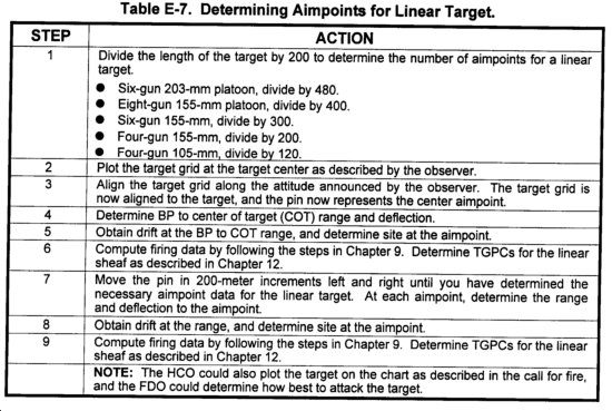
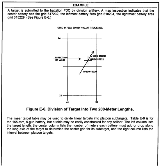
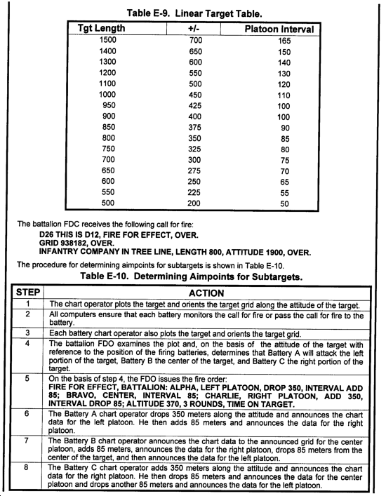
a. Target Division Method. Targets that exceed the firing capability of one battery should be sent to battalion FDC for additional fires. There are times, however, when the battery is forced to fire on targets that exceed its capability. When this occurs, the battery FDO may divide the target into several targets to distribute his fires effectively. (1) Determining aimpoints for a linear target. Because the basic linear sheaf for a four-gun 155-mm platoon is 200 meters, a linear target must be segmented into 200-meter lengths. For a six-gun 155-mm platoon, the length is 300 meters; 8-inch six-gun platoon, 480 meters; and 105-mm four-gun platoon, 120 meters. The procedures for determining aimpoints for a linear target are shown in Table E-7. (2) Determining aimpoints for a rectangular target. Because the four-gun platoon optimum rectangular sheaf is a 100- by 100-meter sheaf, the target must be broken into 100- by 100-meter boxes to effectively engage a large rectangular target. c. Determining Aimpoints for Subtargets. The battalion could receive a call for fire for a large target, or if a battery receives a call for fire and requests reinforcing fires, the battalion FDO must also be able to attack a large target. He uses the firing elements of his battalion to attack the large target, and must be able to determine aimpoints for each firing unit. The battalion FDO will normally divide large or irregularly shaped targets into subtargets for each firing unit. The appropriate subtargets are announced for each unit in the battalion fire order. The fire order should include the center grid and if necessary the attitude. The battalion FDO can also issue guidance in the fire order as to how the subtargets should be subdivided. To determine the aimpoints for the subtargets, the FDO can use the same techniques discussed in paragraphs a and b.
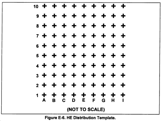
c. Massed Fire Distribution Template. In this method, the large or irregularly shaped target is plotted on the firing chart. A locally constructed massed fire distribution template drawn to scale for the firing chart is placed over the plotted target to allow the user to determine the optimum aimpoints for the required number of firing elements to mass fires. (1) Constructing the Template. Overlay paper is the best material for constructing the template. Each tick mark placed on the template represents an aimpoint for a firing element (Figure E-6). A separate template is required for each caliber, munition type, and size of firing element (one gun, platoon, or battery). (Refer to the appropriate JMEM for this information.) Distance between tick marks is based on the radius of effects of the particular weapon system and munitions to be fired. (Refer to (C) FM 101-60-25.) (2) Using the Template. Table E-11 discusses how to use the template.  FS to the fuze setting to correct for the difference in the height of burst above the target. Therefore, when he requests fire for effect, we assume the observer adjusted the height of burst to 20 meters.
E-4. Replot With Time Fuze
E-5. Attack of Large Targets
|
NEWSLETTER
|
| Join the GlobalSecurity.org mailing list |
|
|
|


