

Part Two. Well Drilling
Chapter 5
Well-Drilling Methods
5-1. Mud Rotary Drilling. Rotary drilling with mud is the most widely used method for water-well construction. A rotary drill rig has three functions: rotating the drill string, hoisting the drill string, and circulating the drilling fluid. A bit is rotated against the formation while mud is pumped down the drill pipe, through ports in the bit, and back to the ground surface through the annulus between the drill pipe and the borehole wall. (Table 5-1 shows the relative performance of drilling methods in various geologic formations.) Drill cuttings rise to the ground surface in the drilling fluid. Rotary drilling is sometimes called mud rotary drilling. Drill pipes or rods are joined to a bit to form the drill string. The drill pipe is the link transmitting torque from the rig to the bit, and the pipe carries the drilling fluid down the hole.

a. Rotary Rigs. Rotary rigs vary in design. Drilling rigs are truck- or trailer-mounted and are powered by an on-board engine or by a PTO from the truck transmission. Power is delivered to the various components through hydraulic pumps and motors or through mechanical transmissions and clutches and geared on roller-chain drives. Many drill rigs may use both mechanical and hydraulic drives. Torque is applied to the drill string, which rotates by using three basic designs--rotary table, top head, and quill-and-drive bar. Military drilling machines use rotary table drives.
(1) Rotary Table. The rotary table is a rotating platform that transmits torque to the drill rod through the kelly. The kelly, which is attached to the mud swivel, is the uppermost section of the drill string that passes through the rotary table. The drill string may be square, hexagonal, or round with grooves or flukes on the outside wall. The drive kelly bar slides through the rotary table while rotating. By removing the kelly bar, you can add drill pipe and work the pipe through the open hole in the rotary table. The rotary table normally is a mechanical, positive drive mechanism.
(2) Top Head. The top-head drive uses a power swivel. Torque is applied at the top of the drill string. The top-head mechanism moves down along the rig mast as the boring is advanced and is raised to the top of the mast to add a length of drill pipe. Top-head-drive drill rigs do not use a kelly bar. Most top-head drives are powered by hydraulic motors capable of variable speeds rather than positive constant rotation.
(3) Feed Drive. Rotary rigs are equipped with a mechanism to apply a downward thrust to the drill string. This mechanism is called a pulldown or feed drive.
Generally, two roller chains apply the thrust for rotary tables. The chains are attached to the kelly swivel and extended over sprockets at the top of the mast and under the rotary table. On older rigs, the sprockets under the rotary table are powered mechanically through a PTO and clutch. The pulldown chains on modem drill rigs are powered by a hydraulic motor, which provides better thrust control.
The thrust mechanism on most top-head rigs is a pair of roller chains consisting of two chain sections. One end of each section is attached to the swivel at the top of the kelly bar. The other ends are dead-headed to the top and bottom of the mast. Sprockets at the top and bottom of the mast act as idlers. Chains are powered in either direction by hydraulic rams. These rams apply thrust and are used in a hold-back mode to reduce the bit load of the weight due to the drill string. This chain mechanism is also the main hoist for lifting the drill string.
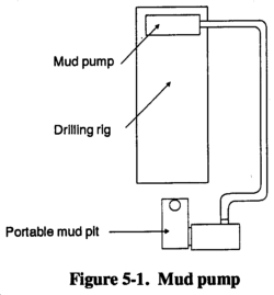
(4) Mud Pump. A mud pump (Figure 5-1) on a rotary drill is usually a positive-displacement, double-acting piston pump with capacities ranging from one to several hundred GPM at pressures up to several hundred psi. Power may be provided through a mechanical PTO and clutch, with or without a separate transmission. Power may also be provided by a separate engine or a hydraulic or air motor. Other types of pumps are often used successfully, but their limited pressure capacity may jeopardize the success of the drilling operation. Most well-drilling machines have dual piston, double-acting, positive-displacement mud pumps. Pump capacity (volume and pressure) can limit the effective depth of a drilling operation. The horsepower required to drive a mud pump often exceeds the power required to hoist and rotate the drill string.
(5) Hoists. Man drill-head hoists (draw works) are mechanically or hydraulically driven wire-line winches. On top-head rigs, the pulldown chains are used as the main hoist. Many drill rigs have auxiliary hoists for handling pipe and other equipment and for bailing. The bailing drum usually has less lifting capacity and a faster spooling rate than hoisting drums. Bailing drums can spool several hundred feet of wire line, which is sufficient to reach the bottom of most wells. Auxiliary hoists may be powered mechanically or hydraulically.
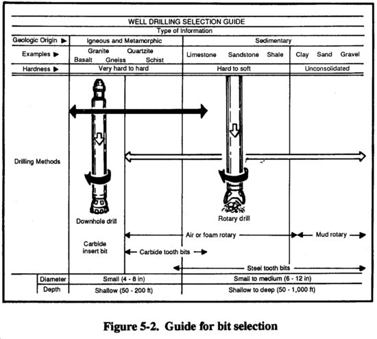
b. Drill Bits. See Table 5-2 for recommended rotating speeds for all sizes and types of bits in various formations. See Figure 5-2 for bit selection. Appendix E discusses characteristics and maintenance for drill bits.

(1) Tricone Roller Bits. These bits bit consists of three cone-shaped rollers are best suited for brittle or friable materials. The tricone with steel teeth milled into the surfaces. Tooth locations are designed so that as the cone rotates, each tooth strikes the bottom of the hole at a different location. Drilling fluid is jetted on each roller to clean and cool it. The cutting action is a progressive crushing under the point load of each tooth. Roller bits designed for rock, rocky soil (gravel), and soft formations (shale) have long teeth. The bits for harder formations have smaller, stronger teeth. The gauge teeth on bits designed for very hard rock are reinforced with webs. For extremely hard formations, milled teeth are replaced with connected carbide buttons.
(2) Drag Bits. These bits are used in soil and other unconsolidated materials. The blades are designed so that they cut into the formation with a carving or scraping action. Drag bits may have multiblade, hardened-steel, finger-shaped teeth or may have connected carbide-reinforced cutting edges.
|
DANGER Remove all jewelry and loose clothing |
c. Rotary Operation. Standard rotary drilling involves the bit rotating against the formation. Drilling fluid is pumped through the drill string and face of the drill bit and backup the annulus to the surface. The rotary action of the bit loosens the material, while the drilling fluid cools and lubricates the drill pipe and bit and carries cuttings to the surface. The drilling fluid is under high hydrostatic pressure and supports the wall of the borehole against caving. The properties of the drilling fluid are important to the drilling operation. Well drillers must have knowledge of drilling fluids and their use for successful rotary drilling. Drillers must also know about drilling-fluid additives used to prevent problems in drilling. Preventing drilling problems, such as an unstable borehole wall or a stuck tool, is easier than fixing the problem after it occurs. See paragraph 5-1e for information on drilling fluids.
Before drilling with mud, build a mud pit. The pit may be either a portable pit or an excavated mud pit. The decision depends on the hole depth and the alternatives available. See paragraph 5-1e(9) for more information on mud pits.
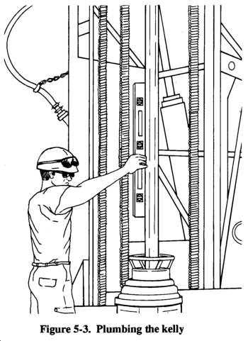
d. Variables. Bit design, weight on bit, rotation speed, fluid consistency, and cumulation pressure and velocity affect rotary drilling. Experience helps the driller handle unique problems and conditions. Continue to experiment wherever you drill to develop the best drilling procedure. Before starting the hole, plumb the kelly to provide a straight hole (Figure 5-3).
(1) Bit Design. Rotary drill bits are designed to cut specific material types. Choose the drill bit based on the anticipated formation. Either drag or rotary bits are available at a drill site. Normally, you will use drag bits for beginning a borehole in unconsolidated overburden materials. These bits are used for hard, medium, and soft rock and are part of the drilling-rig equipment. When drilling in soft rock, use a medium soft-rock drill bit. In very hard rock, stop mud rotary drilling; install casing to the rock layers, use a down-hole air hammer. The objective is to produce a hole quickly and efficiently. Be careful that you do not penetrate too quickly. Producing cuttings faster than you can remove them can cause serious problems, such as the drill string sticking in the hole, excessive completion delays, and loss of equipment and the hole.
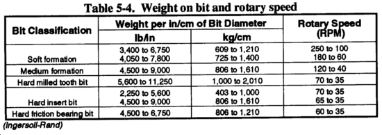
(2) Weight on Bit. Adding weight on the bit increases the torque required for rotation. Too much weight can cause excessive penetration and produce cuttings that are too large and heavy. Large cuttings are difficult to wash out and may cause gumming and premature failure of the bit. Insufficient weight reduces or stops penetration and can produce fine cuttings. In cohesive soils, fine cuttings may thicken the drilling fluid and fail to settle in the mud pit. How weight is applied can also cause serious alignment problems and difficulty in well construction. Rotary-drilled boreholes spiral slightly and are seldom straight. Once spindling occurs, weight added by pulling down with the drill rig bends the string and magnifies the deviation. You should never use the chain pulldown to advance the hole beyond the first run (20 feet). Ideally, keep the drill string in tension. Add drill collars (heavy wall drill steel) at the bottom just above the bit. See Table 5-3 for drill collar weights.

CAUTIONUse the pulldown feature on the drill rig as a |
Bit weight required to cut rock depends on the design of the bit and the strength of the rock. Roller bits need a minimum of 2,000 psi of bit diameter for soft rock and shale and a maximum of 6,000 psi of bit diameter for hard rock. Before drilling, add drill collars instead of drill pipe until the load is sufficient for reasonable cutting. As you dig deeper and add drill pipe, you may have to hold back on the drill string. See Table 5-4 for weight on bit and rotary speed.
(3) Drill Steel. Drill rods, collars, stabilize, subs, and bits are available in different sizes and materials. In most drilling systems, drill rods are either steel or aluminum and come in lengths of either 5 or 20 feet.
(4) Rotation Speed. Rotation speed is determined by the weight on the bit and the material being drilled. Try to regulate the speed to produce the correct size cuttings. Experience will help you determine and regulate rotation speed.
(5) Fluid Requirements. Fluid requirements depend on size, weight, nature of cuttings, and circulation velocity. Velocity depends on capacity and condition of the mud pump, annular area in the borehole, and the stability and permeability of the formation. See paragraph 5-1e for more information on drilling fluids.
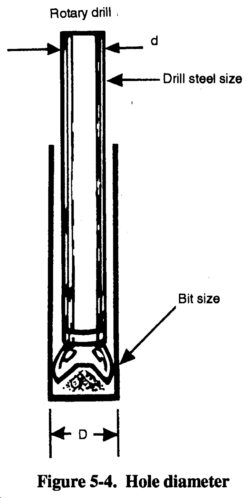
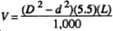
Use the following calculation and Figure 5-4 to estimate the mud-pump output and velocity and the hole size requirements:
V = (D2 - d2)2
where--
V = velocity, in GPM.
D = hole diameter or bit size, in inches.
d = drill steel or drill collar diameter, in inches.
(6) Circulation Pressure and Velocity. These elements of the drilling fluid are controlled by the pump capacity and speed. The fluid's density, velocity, and viscosity let it carry cuttings. If the drilling fluid is too thick, cuttings will not settle in the mud pit. Sufficient velocity with a fluid of low viscosity (even water) will carry drill cuttings to the surface. Excessive velocity will erode the wall of the hole to the extent of failure.
Pump pressure results from flow resistance caused by viscosity, friction, weight of the fluid column, or restrictions in the circulating system. Pressure should be exerted at the ports in the bit, causing a downward jetting as the fluid exits. Regulate mud-pump pressure by varying the RPM of the pump. Mud-pump pressure against the bit is not harmful if it does not exceed the operating pressure of the pump. Other sources of fluid pressure can be detrimental. Pressure from friction occurs if the drill string is long for its inside diameter or pipes are internally upset. Frictional pressure increases wear in the pump. Pressure from the weight of the fluid column in the annulus or from a restriction in the annulus caused by an accumulation of cuttings indicates insufficient cleaning. This type of pressure can cause formation damage, resulting in lost circulation and wall damage.
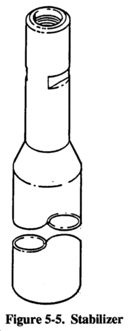
(7) Stabilizers. Unless the drill string includes stabilizers (Figure 5-5) for large drill bits, drill a pilot hole, using drill collars as stabilizers. The initial pilot hole (6- to 7 1/8-inch diameter) will be straighter and easier to sample. The location of aquifers will also be easier to determine. Use a larger bit to ream the hole to the desired size. Use overreaming bits, if available, because they follow the pilot hole best.
e. Drilling Fluids. Drilling fluid is circulated in rotary drilling to cool, clean, and lubricate the drill string, to flush cuttings from the hole, and to stabilize the borehole wall. Water is the basic fluid and is satisfactory for lubricating and cooling the tools. However, water has limited abilities to carry cuttings and stabilize the borehole wall. Many drilling fluid additives are prepared and formulated for various purposes. Polymer fluids and water-based clay fluids (muds) are the primary additives used in water-well drilling. Table 5-5 lists drilling fluids.

Mud cools and lubricates through heat absorption from the bit and reduction of drill-string abrasion against the borehole wall. Heat is generated as the bit scrapes and grinds. Without the cooling fluid, the bit would overheat and be useless. Research indicates that removing the cuttings around and under the bit is the most important factor in keeping the bit cool. Requirements for cooling fluid are less than those for removing the cuttings.
Therefore, if you keep the borehole clean with the fluid as you drill, you also cool and lubricate. This is true with clay muds and polymer fluids. Clay muds are colloidal suspensions. Solutions are chemical mixtures that cannot be separated by simple filtering. Suspensions are physical mixtures of solids and liquid that can be separated by filtering. This distinction underlies the difference in behavior between drilling polymers (solutions) and drilling muds (suspensions). You can mix natural clays with water for use as a drilling mud. Drillers often use water in shallow clayey strata and depend on the formation clay to produce a suitable mud. Natural-clay mud properties are marginal for good water-well drilling.
Hydrostatic pressure allows the fluid to support the borehole wall and is a function of the density or weight of the mud column. Important characteristics of a drilling mud are viscosity and weight to carry cuttings, gel strength, yield point, and active clay solids for filter cake. Use the following formula to calculate hydrostatic pressure:
where--
Hp = hydrostatic pressure, in psi.
Md = mud density, in pounds per gallon.
d = hole depth, in feet.
For example, the hydrostatic pressure of a 200-foot hole with a mud weight of 9 pounds is as follows: 9 ft x 200 ft x 0.052 = 93.6 psi.
(1) Polymers. Polymer fluids are water-based and very low in solids. The polymer admixture can be organic, inorganic, natural, synthetic or synthetically formulated natural polymers. Polymer additives are formulated for various drilling-fluid purposes and can be used alone or to enhance clay muds. Polymers, containing salt and other contaminants, are available and are compatible with water. Polymers are more sensitive to pH than are bentonite muds. Change the pH to effect desirable changes in the polymer fluid. Drilling-fluid weight impacts drilling rate and high-density drilling fluid reduces drilling rote. There is strong indication that the solids of a fluid have a similar effect as density. Polymer fluids are very different from clay muds because a large part of the polymer is soluble in water and becomes a solution when mixed with water. Long, complicated molecular chains tie up the water and can build viscosity without solids. In water-well drilling, many polymers are manufactured for producing drilling fluids, such as E-Z Mud, Revert, and Poly-Sal. E-Z Mud is a synthetic, inorganic polymer. Revert is a natural, organic polymer fluid derived from the guar plant.
Polymers are generally best mixed through a mud gun. Polymers used for special purposes are available from the manufacture complete with specifics on how to use the product. Most polymers can hydrate more water than a high-grade bentonite. Up to ten times more bentonite is needed to build the same viscosity in a given amount of fluid, depending on the quality of the polymer. A polymer does not fully hydrate as quickly as bentonite. Mix the polymer very slowly through the mud gun a minimum of four hours before using for more complete hydration. The fluid will thicken as hydration continues, so do not mix to the desired viscosity. Some polymers possess physical qualities that can result in unusual hydration, gelling and viscosity. Follow the manufacturer's recommendations for hydration. Factors that affect the viscosity are quality of polymer, concentration and size of colloid, metallic ions in mixing water, temperature, rate of shear, and pH.
Water is the primary building block for drilling fluids. Water quality affects the overall performance of drilling fluids. The action of bentonite in water is seriously impaired by dissolved acids or salty substances. Acidic water usually contains dissolved metals that cannot be used unless treated. Hard water affects the suspending and sealing qualities of bentonite. You can test the pH level by using paper pH strips. The pH level should be 8 to 9. If the water is too acidic, treat it with soda ash at a ratio of 1 to 5 pounds of soda ash per 100 gallons of water. Following treatment, retest the pH level as before.
Do not use water from wetlands, swamps, or small ponds for mixing drilling fluids because the water may be contaminated. If you use water from these sources, chlorinate the water before making the drilling fluid. Be careful because chlorine removes metallic ions that are necessary for viscosity in polymers. Adjust the pH of drilling water to 7.5.
Temperature affects the viscosity and stability of some polymers. Consider the following examples:
- Seven pounds of Revert per 100 gallons of water at 45°F yields Marsh funnel viscosity of 125 seconds per quart. The same mix at 85°F yields 70 seconds per quart.
- A 0.87 weight mix of Revert at 68°F F yields a viscosity above 90 seconds per quart for three and a half days. The same mix at 80°F maintains viscosity of 80 seconds per quart for only two days.
Polymer drilling fluids can break down viscosity. Without treatment, the viscosity of some polymers (Revert) completely breaks down in one to six days depending mainly on temperature. You can correct this by adding chlorine. Revert requires Fast Break; E-Z Mud needs sodium hypochlorite at a ratio of 2 quarts for every 100 gallons of water. Other polymers, such as E-Z Mud and Poly-Sal, maintain their viscosity for long periods of time since natural breakdown is not significant. Table 5-6 lists additives for drilling fluids.

Polymer drilling fluids have virtually no gel strength because the colloids are nonionic and exhibit no attraction for each other. Most of the drill cuttings should be washed out of the borehole before circulation is stopped. A polymer fluid does not have thixotropic properties to hold cuttings in suspension. Shakers, desanders, or desilters are not needed when using polymer fluids. Since most of the cuttings are dropped out, friction and wear in the pump are minimized and the drilling rate is not impeded by cuttings or high density. A major advantage of polymers is the lack of mechanical wear to the drill-rig mud system.
Some drilled fines (clay, silt) circulate back down the hole. Recirculated solids are much less a problem with polymer fluids than with clay fluids. Revert will not hydrate in water containing any appreciable amount of borate. However, Borax can be used to produce a gel plug in hydrated guar-gum polymer. With a pH of 7.5, the borate cross-links the polymeric chains and forms a strong three-dimensional molecular gel. If a strong gel plug is necessary to get through a lost circulation zone, mix 1 cup of borax in 5 gallons of water and pour slowly into the pump section while pumping at idle speed. When the berated fluid (stringy gelled mass) recirculates, stop pumping for one-half hour. Resuming normal drilling should be possible after wasting the borated fluid. Repeat the procedure, if necessary. Although the polymer fluid is not thixotropic and has no gel strength, it thins somewhat while being pumped.
Polymer fluids build a type of membrane on the wall different from clay mud. Unnatural clay particles (bentonite) are not introduced into the hole. Since the polymer fluid is partly a thick solution, infiltration into the permeable wall is reduced. However, insoluble portions of some polymer colloids do exist. The insoluble and cuttings are surrounded with thick coatings that are more impermeable per unit thickness than a bentonite filter cake. The insoluble and cuttings seal the wall of the hole with a thinner, less active layer. The impermeable layer performs the same function as the filter cake in clay muds but does not restrict the annulus.
The colloids in the polymer fluid are nonionic, have no chemical interaction, and are easier to remove in water-well development. When the viscosity of the fluid is broken, much of the cohesive function of the thin film becomes a water-like liquid and is washed out of the water well. Field testing of polymer fluids, using the falter press and the Marsh funnel, yields different results. The mud balance for measuring fluid density does not change. Weighing of the polymer fluid is limited. You can add sodium chloride to the fluid to bring the weight up to about 10 pounds per gallon. The addition of heavy solids (ground barite) is ineffective because of the polymer fluid's lack of thixotropic qualities.
(2) Mud Products. Commercially processed clays for drilling are bentonite and attapulgite. Bentonite is superior except in brackish or salty water. (Use attapulgite in these waters.) Bentonite forms naturally from decomposition of volcanic ash when ground. Bentonite consists of aggregates of flat platelets in face-to-face contact. Bentonite is mined in many states, but the best grade (Wyoming bentonite) is mined only in Wyoming and South Dakota. Wyoming bentonite contains sodium montmorillonite (the active part of the clay mineral) and is small in size, which is important in building viscosity.
Mud drilling fluids should be mixed with a mud gun. When agitated and sheared with water, the bentonite platelets absorb more than 25 times their own weight in water, separate, and swell. The amount of surface area wetted determines the ability of the particle to build viscosity. One ounce of Wyoming bentonite dispersed in water has more surface area than five football fields. Interparticle activity between platelets gives the mud its gel properties. The chemical composition of the mixing water affects the ability of bentonite to develop desirable qualities. These qualities can be manipulated by adding small amounts of various chemicals.
(3) Mud Viscosity. True viscosity is a term relating only to true (Newtonian) fluids, such as water, and is a proportional constant between shear stress and shear rate in laminar flow. Drilling muds act differently in that the proportion between shear stress and shear rate is reduced when shear rate is increased. Drilling muds are thixotropic. The viscosity of a drilling mud refers to the thickness of the mud while flowing. Gel strength is the term used to describe the thickness of drilling mud at rest. Gel strength develops over a short period of time.
Yield point is the mud quality broadly included in viscosity. You need more stress (pump pressure) to cause the gelled drilling mud to start flowing than to sustain flow once the gel is broken. The stress required to initiate shear or flow is the gel strength of the mud. The stress required to maintain shear is the viscosity. You want a higher yield strength with respect to the gel strength so the mud becomes very thin in flow shear.
The primary function of viscosity is to help lift drill cuttings from the borehole. Other mud characteristics affecting lifting capacity are density, velocity, and flow patterns. Gel strength holds the cuttings in suspension at the bottom of the hole when circulation is stopped. The stress (hydraulic pressure) required to break the gel strength to initiate cumulation can be detrimental. Required bottom-hole pressures can cause fracturing or opening of fractures in the formation, resulting in loss of drilling fluid, formation damage, and borehole wall damage. Down-hole pressure required to continue circulation depends on friction, density (or weight of fluid column), and viscosity of the mobilized fluid. These pressures can also cause serious problems. Therefore, it is desirable to use a drilling mud of relatively low density and viscosity, moderate gel strength, and high yield point relative to the gel strength (a very thin fluid in circulation).
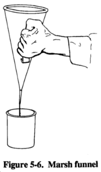
(4) Mud Testing. The Marsh funnel (Figure 5-6) is routinely used to give an indication of thickness or apparent viscosity of drilling fluid. The Marsh funnel is 12 inches long and 6 inches in diameter and has a No. 12 mesh strainer and a 1,000-milliliter (ml) cone. The funnel has a 2-inch-long, calibrated, hard-rubber orifice with an inside diameter of 3/16 inch. The funnel's cup is marked with a capacity of 1,000 ml. Use the following procedure for the Baroid Marsh funnel:
- Hold or mount the funnel in an upright position, and place a finger over the hole.
- Pour the test sample, freshly taken from the mud system, through the string in the top of the funnel until the level touches the top of the screen.
- Immediately remove the finger from the outlet tube, and measure the number of seconds for a quart of mud to flow into the measuring cup.
- Record time in seconds as funnel viscosity.
NOTE: Calibration time for fresh water at 70°F is 26 seconds.
- The funnel viscosity measurement obtained is influenced considerably by the gelation rate of the mud sample and its density. Because of these variations, the viscosity values obtained with the Marsh funnel cannot be correlated directly with other types of viscometers and/or rheometers. Graduated in cubic centimeters (cc) and fluid ounces, the 1,000-cc measuring cup is designed specifically for use with the Baroid Marsh funnel viscometer. A quart volume is clearly marked on the measuring cup.
The desired mud consistency depends on many factors. The nature of the formations will dictate mud qualities. However, you will not know all the conditions before you start to drill. The inexperienced driller must be careful because mud with the correct thickness often is too thin. You can adjust the viscosity by adding water or clay. A good range for drilling muds is 32 to 50 seconds per quart. Viscosity is influenced by mud density, hole size, pumping rate, drilling rate, pressure requirements, and geology. Considering the thixotropic qualities of drilling mud, a funnel viscosity of 100 seconds per quart may be no more viscous than a funnel viscosity of 50 seconds per quart if both fluids are in motion.
You can use test readings as an indicator of changes in mud that might lead to problems. Therefore, conduct Marsh-funnel tests before beginning operations and record the findings. Take mud samples for each test from the same location in the circulating system just before returning to the hole. The apparent viscosity of the drilling mud in motion affects carrying capacity, the pump pressure (hydrostatic down-hole pressure) required for circulation, and the ability to drop cuttings in the settling pit. These characteristics are also intrinsically involved with well hydraulics, density of mud, density and size of cuttings, and particle slip.
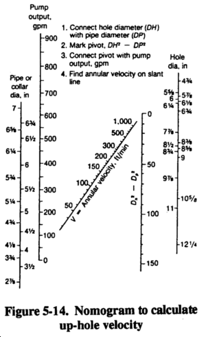
(5) Density. The carrying capacity of a mud is affected by its density and the density of the drill cuttings. If the cuttings are denser than the fluid, they will descend. The magnitude of the difference in density, particle size, and fluid viscosity affect the rate at which a particle descends. Particle slip denotes this downward movement through the fluid. Ignoring thixotropy, the actual downward particle slip is constant regardless of velocity of flow. However, when the upward velocity of fluid exceeds the downward particle slip, the new movement of the particle is upward. Up-hole velocity plays a major role in determining the carrying capacity of the cumulating fluid. The practical limits of up-hole velocity depend on pump size and capacity, inside diameter (ID) of the drill string, jet size in the bit, viscosity of the fluid, cross-sectional area of the annulus, and stability of the borehole wall. Up-hole velocity is not as simple as the comparison of pump capacity, drill string ID, and annulus. Up-hole velocity is not a constant.
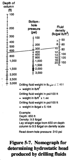
The density of the drill fluid serves other purposes in rotary drilling. Heavy fluids can control (hold down) formation pressures encountered in drilling. You can build heavy mud by adding a weighing material such as ground barite (specific gravity 4.25). Prepare drilling mud in excess of 20 pounds per gallon by using barite. First, mix bentonite and water to build viscosity. Then, add finely ground barite so the mud will hold the barite in suspension. Use heavy drilling mud only when absolutely necessary to control pressures since the muds have disadvantages. High-density mud increases pressure on the formation by the weight of the fluid column. Figure 5-7 shows the nomograph for determining the hydrostatic head produced by drilling fluids. The increased pressure is further increased by the pump pressure required to mobilize the fluid in circulation. The increased pressure can cause formation damage and loss of circulation. In formations that are strong enough to withstand the pressures without being damaged, the drilling operation can still suffer.
The pressures from the mud and the formation should be balanced so that the borehole bottom exposed to the drill bit is near surface eruption from pore pressure. That balance makes the formation easy to fracture and enhances the cutting rate. If the mud pressure is much lower than the formation pressure, the borehole can be unstable. If the mud pressure far exceeds the formation pressure, the cuttings may be suppressed and reground by the bit. The result of recutting reduces bit life and lowers drilling rate. Mud density is increased by drill cuttings; the mud rising in the hole is heavier than the mud returning to the hole.
All cuttings should be removed from the drilling mud in the settling pits and not recirculated. Although 100 percent removal is unrealistic, well-designed mud pits and mechanical screens, desanders, and desilters materially aid in removing cuttings from the mud. Water weighs 8.34 pounds per gallon. Clean, low-solid bentonite mud can weigh 8.5 to 9.0 pounds per gallon; try to maintain that weight. Increasing density of the mud during drilling indicates that the mud contains native solids. The drill's penetration rate could be exceeding the combined effort of the mud pit, desanders, and fluids to effectively separate solids from the drilling mud. To correct this problem, slow down the penetration rate and run the desanders to remove the solids.
You can determine the density or weight of the drilling mud using a mud balance. Fill the mudbalance cup with mud, and place the inset lid in the cup. Excess mud will be displaced through a hole in the lid. Clean the outside cup area, place the assembly on the center pivot, and balance it using sliding weight. You read mud density as pounds per gallon and pounds per cubic feet. If you know the mud weight that enters and exits the drill hole, you can evaluate the efficiency of the mud pit and mechanical separators, determine when to clean the mud pit, and tell how well the mud is cleaning the hole. If you take samples from only one location, take them from the return end of the pit.
(6) Filter Cake. Filter cake consists of solids from the drilling mud deposited on the borehole wall as the water phase is lost into the formation. Desirable properties are thinness and impermeability. Drilling mud is a colloidal suspension that can be separated by simple filtering. With the hole kept full of mud, the hydrostatic pressure inside usually exceeds the formation pressure. Occasionally, an artisan aquifer is penetrated, with formation pressure higher than the hydrostatic in-hole pressure. When the borehole pressure is higher than the formation pressure, the drilling mud tends to penetrate more permeable formations. Solids from the mud filter out and deposit on the wall, and the liquid phase of the mud (filtrate) enters the formation.
Filter cake can be compacted against the wall by the excess hydrostatic pressure in the borehole. If the drilling mud is a well-conditioned bentonite and water mixture, most of the solids plastered against the wall will be flat platelets of highly active clay. The filter cake is self-regulating based on its degree of impermeability. As long as filtrate can pass through, the filter cake continues to thicken. A thick cake detrimentally increases down-hole cumulating pressure by restricting the annulus, making it difficult to pull the drill string because of the physical size of the drill collars and bit. In deep and somewhat deviated holes, the danger of key seating increases. Because a thick filter cake is of a lower quality and depends on its thickness to be effective, it is more easily damaged and eroded. A thick filter cake may indicate that the fluid has a high percentage of native solids. You may have to clean these solids from the mud before drilling progresses.
A thin, highly impermeable filter cake bonds well to the wall and provides a surface for the hydrostatic pressures to act against to support the wall. Filtrate loss into the formation can account for significant fluid loss, if the consistency of the drilling mud is not good. Good consistency does not necessarily mean thick; it has to do with the bentonite content and the quality of falter cake. If a permeable formation is encountered with pore spaces too large to be plugged by the fine bentonite particles, the drilling mud will enter the formation. That mud loss can take the entire output of the mud pump. The drill cuttings being carried up the annulus can sometimes be beneficial. The cuttings are coarser than the bentonite particles and may help bridge across formation pores. If you use this technique, maintain the normal drilling rate to supply the cuttings. Slow down the pumping rate to reduce pressure on the formation while bridging the open spaces. With sufficient bridging, a suitable filter cake follows, circulation is regained, and normal drilling operations are resumed.
In the field, you can test the filtration properties and filter-cake thickness using the filter-press kit. This kit consists of a press with a mounted pressure gauge and a CO2 charging system that is used to simulate the hydrostatic pressure inside a 200-foot hole. By placing a sample of drilling mud in the press and charging the system, you can forma filter cake. The filter cake should be less than 2/32-inch thick.
(7) Salty Environment. A high chloride content in the mixing water causes bentonite to react anomalously or not react at all. The ground bentonite remains agitated; it does not disperse, hydrate, or swell. In salt water, bentonite is an inefficient clay additive for drilling mud. The dissolved salt is an electrolyte that changes the interparticle activity of bentonite. If you add sufficient amounts of salt water to a fresh water and bentonite mud mixture, the dispersed platelets will form lumps. Viscosity and filtrate loss increase and the mud's ability to build a thin, impermeable filter cake decreases.
Attapulgite is often used for salty formations. The small particles produce a high surface-area-to-volume relationship and good viscosity building. Unlike bentonite, the particle shape is needle-like. Viscosity building in attapulgite depends on the entanglement of these needles. The disorderly arrangement of the particles accounts for the poor filtration qualities of attapulgite. The filter cake is more like a layer of strew or sticks. Attapulgite clay does not have the physical qualities to build a thin, impermeable filter cake. If you can mix bentonite in fresh water first and then add salt water as make-up water, the bentonite flocculates; that flocculation can be reversed by chemical treatment.
(8) Well Hydraulics. You must have a basic understanding of well hydraulics. Fluid is pumped down the drill string, out the ports in the bit, and up the annular space between the drill string and the wall. The fluid empties into the mud pit, through any mechanical solids separating equipment, and is picked up from the pit by the mud pump for recirculation. The system is intended as a conservation system. Except for mud lost into the formation or where artisan water exceeding hydrostatic pressure flows into the hole, the return is largely complete and the mud-pit level does not change. Even if the system is in equilibrium, you need to understand the up-hole rearrangement of flow patterns.
Fluids flow in two distinct patterns. Laminar flow is orderly. The streamlines remain distinct and the flow direction at every point remains unchanged with time. Turbulent flow is disorderly. The flow lines and directions are confined and heterogeneously mixed. The type of flow depends on the cross-sectional area of the fluid course and the velocity, density, and viscosity of the fluid. In water-well drilling, the cross-sectional area of the annulus is usually several times that of the inside diameter of the drill string. Because of the increase in volume in the annular space, flow at the point the fluid leaves the bit is turbulent. The fluid becomes laminar flow when it begins flowing up the annular space. The returning fluid velocity is slower and the drill fluid is more dense and probably has more apparent viscosity, which affects the flow pattern. To clean the hole and carry the drill cuttings out, turbulent flow in the annulus would be better.
Picture the flow in the annulus as a series of nested tubes. Velocity varies as if these tubes were sliding past one another while moving in the same direction. Flow near the wall and near the drill string is at a slower rate than near the center. Cuttings near the center can be vigorously lifted while cuttings near the wall and drill string actually slip in a net fall. Rotation of the drill string changes the flow pattern near the drill string and materially enhances particle lift.
For example, if you use a 3 1/2-inch ID and 4-inch outside diameter (OD) pipe to drill a 9-inch hole and pump 200 GPM, the velocity of the ID pipe is 400 feet per minute (fpm) and the velocity of the OD pipe is 75 fpm. To test cumulation at these rates (bit is 300 feet deep), pump down a marker (strew or oats). The majority of the material should take 4 minutes and 45 seconds to return (300 feet at 400 fpm takes 45 seconds and 300 feet at 75 fpm takes 4 minutes). To clean all the cuttings from a 300-foot depth with an average up-hole mud velocity of 75 fpm will require more than four minutes of pumping. Consider this concept regarding sampling cuttings from the return mud.
If cuttings remain in the annular space between the drill rod and borehole wall when circulation is stopped, they will produce a denser fluid than the clean drilling mud inside the drill rods. The denser mud in the annular space will then flow down the hole and force the clean drilling mud up the drill rods. This causes a geyser effect, and the drilling mud may shoot several feet into the air until the mud columns equalize. (Some drillers mistake this for a caving hole.) If this situation happens when adding drill rods, the circulation time should be increased after drilling down the next rod. Use the following formula to calculate the annular space volume:
where--
V = annular space volume, in cubic feet.
D = hole diameter or bit size, in inches (Figure 5-4)
d = drill hole or drill steel collar diameter, in inches (Figure 5-4)
L = hole length, in feet (Figure 5-4)
(9) Mud Pits. Rotary chilling preparation is the design and excavation of an in-ground mud pit or installation of a portable mud pit and the mixing of the drilling fluid. For standard drilling operations that use well-completion kits, well depths could range from 600 to 1,500 feet. For wells up to 600 feet using the 600-foot WDS, use portable mud pits. For wells over 600 feet, use dug mud pits. In either case, you will have to clean cuttings from the pits as drilling progresses. Design considerations include the anticipated depth and diameter of the drill hole, since the material cuttings from the hole will be deposited in the mud pits.
The volume of the pits must equal the volume of the completed hole. Therefore, during drilling, you will have to clean the cuttings from the pits frequently. If you have a backhoe to dig and clean the pits, size and depth of the pits are not critical. If you must dig and clean the pits with shovels, width and depth are important. Drilled cuttings should drop out of suspension in the mud pit. Therefore, long, narrow pits are better. Figure 5-8 shows a mud-pit layout and a chart depicting mud pit capacities and dimensions.
NOTE: Portable mud pits will require constant cleaning.
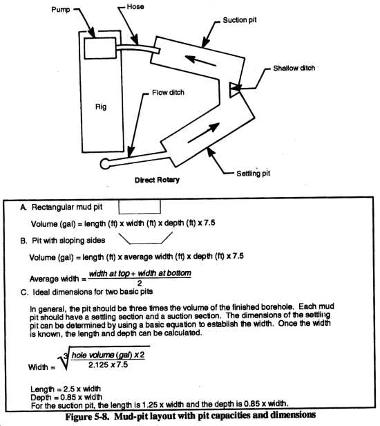
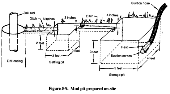
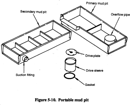
Mud pits are part of the circulating system for mixing and storing drilling fluid and for settling cuttings. The ground slope will affect site layout. Pit design can enhance pit performance. Most drillers agree that using multiple pits is best when dropping drill cuttings from the fluid. The volume of the pit should be one and one-half to three times the volume of the hole. This will provide fluid to fill the hole and an excess volume to allow stilling and settlement or processing before returning to the drill string. A volume of three times the hole volume will minimize drilling-fluid and mud-pit maintenance. Figure 5-9 shows a mud pit that is prepared on-site. Figure 5-10 shows a portable mud pit.
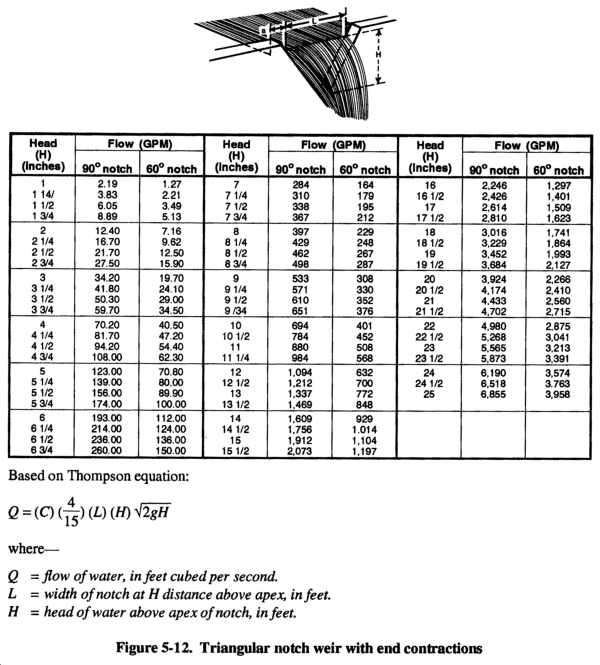
If you use a clay-based mud with thixotropic qualities and the mud moves slowly or flow stops, the gel strength can hold the cuttings. High velocity through narrow, shallow trenches holds the cuttings in suspension. If mud runs over one or more wide baffles or weirs, flow shear and velocity are low. These factors enhance cuttings to drop out. If mud processing equipment is available, use it. Recirculating clean fluid reduces power requirements, wear, and erosion and enhances drilling rate. See Figure 5-11 and Figure 5-12 to calculate weir dimensions and volume.

f. Rotary Drilling Problems. Some problems in rotary drilling are minor and others are serious and can result in failure to complete a hole or even loss of equipment. Many serious problems start minor but can become serious if not recognized or handled properly. For example, in a loose sand zone, the borehole walls can slough and cause drilling fluid loss. By reducing or increasing fluid velocity, you can stabilize the wall and regain fluid circulation. However, if you do not recognize the condition and you continue drilling, the wall will slough and create a cavity. The cuttings lose velocity, become suspended in the cavity, and tend to fall back into the hole when you add a rod. This action can result in the rods or the bit becoming stuck in the hole. Other problems can result from subtle changes in geology, imbalances in the drilling operation, or equipment failure.
(1) Lost Circulation. Lost circulation refers to a loss in volume of drilling fluid returning to the surface. The implication is that some fluid pumped down the drill pipe is entering the formations. The mud pit will lower, since some of the mud is used in forming a mud cake on the borehole wall; however, increased lowering can indicate circulation loss. Losses can occur through open-graded sand or gravel or open joints in rock. A loss can occur when cuttings are not washed out and the borehole annulus becomes restricted, resulting in increased down- hole pressure. Spudding (raising and lowering the drill string) the hole too violently can cause loss. Spudding helps wash cuttings, but down-hole pressures increase momentarily. Experienced drillers can estimate when spudding is safe. When fluid cumulation is lost and a driller continues to drill, he is drilling blind. An experienced driller that knows the rig can often drill blind successfully, but reestablishing circulation is always safer.
Reestablishing circulation can involve several techniques. You can add commercial items such as chopped paper, straw, cottonseed, and nut hulls to the mud pit. Sometimes, while the loss zone is grouted and redrilled, the grout is lost into the formation. In this situation, you may have to set casing through the loss zone. Occasionally, reducing fluid velocity while continuing to drill will plug the loss zone with drill cuttings. Reestablishing circulation is usually a trial-and-error process. The longer you drill without circulation the more difficult it will be to reestablish circulation.
(2) Fall-In. Fall-in is material that accumulates in the bottom of the borehole after you stop cumulation. This material is borehole-wall material that results from sloughing or caving or cuttings previously carried in suspension. Fall-in occurs when you encounter a loose, unstable formation and the drilling-fluid weight is insufficient to stabilize the formation. If you anticipate or suspect fall-in, raise the drill bit off the bottom of the hole (20-foot minimum) each time drilling is interrupted. This will prevent the cuttings and fall-in from settling back around the bit until the problem is solved.
(3) Stuck Drill String. The drill bit and any collars just above the bit are larger in diameter than the drill pipe. The string becomes stuck when cuttings collect on the bit and collar shoulder. This condition is called sanded in. Be careful because you can break the drill pipe while trying to remove the drill string. Regaining circulation and working the sand out are seldom successful. If the formation will not take the fluid when you engage the pump clutch, the relief (pop-off) valve will operate to relieve the pressure. Little can be done to free the drill string except to wash a small pipe down the annulus to the bit and jet the settled sand back into suspension. When the annulus is too small to pass a jet pipe, a part of the drill string may be lost.
DANGERNever try to stop the relief-valve operation to get higher |
When the annulus is small, excessive up-hole velocity can promote erosion of the filter cake in granular zones and allow caving against the drill pipe. If this occurs, try to maintain circulation and rotation, even if circulation is slight. Where the grains are angular, the drill pipe can become locked while being rotated. This situation is similar to a sanded-in bit. With smooth pipe (not upset), hammering up and down will sometimes dislodge the string. You can reestablish circulation and continue drilling. Be careful because hammering up and down can produce unfavorable compacting of the sand. In a hole of fine-grained soil or shale, where the alignment has significantly deviated and the drill pipe has wallowed into the wall, the pipe can become wall stuck. Pipe friction and relatively high borehole pressure can move the pipe tighter into the wallowed groove as you pull the string. An alert driller should recognize early stages of deviation and take measures to realign the hole.
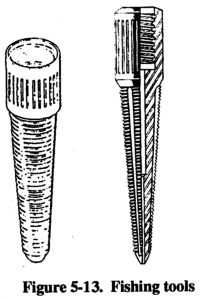
(4) String Failure. When the drill string parts, leaving a portion in the borehole, the drill string is rung off. The portion in the borehole is a fish and attempts to retrieve the portion is fishing. Fishing tools include a tapered tap and an overshot die (Figure 5-13). Ringing off is normally fatigue failure in the drill-rod joints caused by excessive torque or thrust (repeated flexing and vibration that crystallizes heat-treated tool joints) or by borehole deviation (with flexing of the string). Examine drill rods for signs of failure.
(5) Deviation. A deviated borehole is called going crooked. If you make the initial setup without plumbing the kelly, you can expect the borehole to go crooked. A crooked borehole usually amplifies other problems and can make a borehole unsuitable for a well. You should always anticipate deviation, since the borehole naturally tends to spiral from bit rotation. Variations in the formation badness may start deviation. Excessive bit load magnifies minor initial deviation. Use all available guides and collars and a reduction in bit load to minimize deviation.
(6) Swelling Soil. The in-hole effects of swelling soil (shale or clay) that absorbs water from the drilling fluid is squeezing. The result is a borehole that is undergauged to the extent that you cannot pull the bit by normal hoisting methods. In such cases, you can cut back through the blockage with a roller rock-bit or a drag bit. Swelling can cause caving and failure of the wall. Keep water out of the formation to prevent swelling. Special polymer drilling fluid additives that limit water absorption are available. High quality bentonite forms a thin but highly impermeable filter cake.
5-2. Air Rotary Drilling. Air rotary drilling is similar to mud rotary drilling except that the fluid circulated is compressed air. The air is not recirculated. Using compressed air is advantageous when water for drilling is inconvenient, fluid is being lost to the formation while drilling, or you have difficulty washing sticky clay formations from the hole. Also, air rotary drilling requires much less development time. You may have to adjust air rotary techniques with each well you drill. Some disadvantages to air rotary drilling are that air cannot support the wall of a hole in an unstable formation, changes in the return air flow are not as readily apparent as in mud flow, and air is not as effective in cooling and lubricating the drill bit and string.
a. Air Supply. Air has no density or viscosity, so cuttings are blown out of the hole at high velocity. The up-hole air flow is turbulent and more effective in lifting the cuttings. The lack of density and viscosity increases the particle slip so a continuous and high velocity up-hole flow must be maintained to keep the hole clean. An upward velocity of about 4,000 fpm is sufficient to clean cuttings out of the hole. Cutting removal also depends somewhat on size, density, and amount of cuttings. Up-hole air velocity is computed by dividing the output volume of the air compressor, in cfm, by the cross-sectional area of the annulus of the hole, in feet. Air compressors are rated on the following items:
- Intake air volume.
- Condition. Compressors wear with use, causing capacity to decrease.
- Sea level. Output volume capacity is reduced about 3.5 percent for every 1,000 feet above sea level.
- Temperature. Efficiency is reduced when temperatures are above 60°F and is increased when temperatures are below 60°F.
- Rotation speed. Output from the compressor is directly proportional to the motor's RPM. Do not operate a compressor at lower RPM to reduce wear.
Dry material drilled by air will create a large amount of dust when blown from the borehole. Inject water to control the dust. Depending on the nature of the material drilled, the amount of water could be 1/2 to 5 GPM. Water injection increases air density and improves carrying efficiency for the cuttings. Adversely, water can cause the cuttings to stick together, making them heavier and harder to blow out of the borehole, or the cuttings may stick to the borehole wall, causing constriction.
Minor wetting or dampening makes some walls more stable; excessive wetting can cause a wall to fail. Adjusting the amount of water injected into the borehole takes experience. Air has no wall-stabilizing qualities. In soils where sloughing and caving are a problem, injection of a thin drilling mud (bentonite mixed with the injection water) will control the dust and can contribute to stability.
In drilling large diameters (12 inches) with standard drill pipe (3 1/2 inches OD), the annulus equals 0.7 square feet. Using a 1,000-cfm compressor the up-hole velocity would be about 1,400 fpm, which is not enough velocity to remove cuttings. While penetration will progress, the cuttings tend to stay at the bottom of the borehole under the drill bit and are recrushed. These cuttings act as a pad under the teeth of the bit and prevent proper cutting action. The compressor normally cannot drill holes by straight air rotary.
Use the following equations to estimate compressor size, up-hole velocity, and hole-size requirements for air drilling or Figure 5-14 to determine up-hole velocity. The recommended up-hole velocities are: 3,000 fpm, minimum; 4,000 fpm, fair; and 5,000 fpm, good.
where--
Vmin = minimum velocity, in cfm.
D = hole diameter or bit size, in inches (Figure 5-4).
d = drill steel or drill collar in diameter in inches (Figure 5-4).
and

where--
V = actual up-hole velocity, in fpm.
C = compressor capacity, in cfm.
Vmin = minimum velociy, in cfm.
Air drilling has a depth limitation because of water in the borehole. Air pressure must displace the head of water in the borehole before it can exit the bit. An advantage is that when you encounter water, it. will discharge with the air. As drilling progresses, you can estimate the amount of inflow to the well. When calculating the static head of water, remember that 0.434 psi equals 1 foot of head or 1 psi equals 2.3 feet of water. For example, the minimum psi required to overcome a 400-foot static water-level column is 173.6 psi (400 ft x 4.34 psi= 173.6 psi).
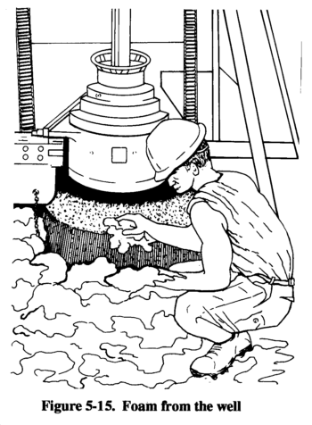
b. Foamers. Commercial foamers for drilling enhance the air's ability to carry cuttings and reduce the velocity required to clean the borehole. The foamer is mixed with the injection water but does not foam with gentle stirring; therefore, pumping is not hindered. Foam must be pumped at a pressure greater than the air-line pressure into which it will be injected. The foaming and mixing with air largely occurs when exiting the drill bit. If air flow is reduced from the volume required for air rotary drilling and the injection rate is tuned to the airflow, the foam leaves the hole as a slow-moving mass (Figure 5-15). The foam is laden with drill cuttings and the borehole is effectively cleaned with only 10 percent of the air volume required had foam not been used. You can drill boreholes 2 feet or more in diameter with a well-tuned air-foam operation using air compressors. See Table 5-7 for a list of common problems with air-foam systems.

Commercial foamers vary and come with mixing instructions on the container. You may need only a few foamers to produce large volumes of rich foam. Less than one quart of foamer mixed with 100 gallons of water injected at a 2- to 3-GPM rate is sufficient for a 12-inch diameter borehole. The column of foam provides slight stabilization to the wall. You can increase the richness and density of the foam by mixing bentonite with the injection water before adding the foamer. A very thin fluid of 15 to 20 pounds of bentonite mixed in 100 gallons of water is suitable for injection in air-foam drilling.
Adding foamer to this fluid in the same proportions as clear water, results in richer, more stable foam. This technique is sometimes called air-foam-gel drilling. The gel refers to the bentonite fraction. Because of the increased richness, stability, and density of the air-foam gel, the air's cutting-carrying capacity and the wall stabilization are enhanced. Foam reaching the surface must be carried away from the drill rig to avoid mounding over the work area. Foam eventually dissipates when exposed to the atmosphere. Use either of the following methods to remove the foam from the rig area:
- Method 1. Use a packer to seal the top of the surface casing around the drill pipe or kelly bar so either rotates freely. Fit the top of the surface casing with a T below the packer for connecting a waste pipe. As foam comes out of the waste pipe, remove it from the rig.
- Method 2. Place a T at the top of the casing with an air-line eductor that causes a vacuum at the top of the hole. The foam is vacuumed into and blown through the waste pipe. By using an eductor, you can observe and regulate the returning foam. The eductor is fabricated and the drilling operation does not usually require the full output of the compressor.
5-3. Percussion Drilling. This type of drilling involves crushing by impact of the teeth of the drill bit. Most percussion drills are actuated by compressed air (pneumatic percussion). Essentially, percussion drilling for water wells uses down-hole, pneumatic-percussion hammer drills. Down hole means the percussion motor (actuating device) is at the bottom of the drill string.
Percussion drills are best suited for drilling brittle, moderately soft to hard rock. In hard rock with percussion drills, you can drill faster and more economically than with other drilling methods. The air blows the cuttings from under the bit and up the annulus to the surface. The air's ability to carry the rock chips depends primarily on high air velocity. An up-hole velocity of about 4,000 fpm is required to remove cuttings. If drill penetration rates are high (30 fpm or more), you may need a higher up-hole velocity to clean the hole. To drill water wells with percussion drills, you need to balance drill paragraphmeters to the materials to be drilled.
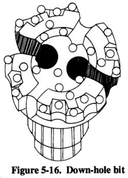
Down-hole hammer drilling with a large diameter hammer or bit (Figure 5-16) usually results in a very crooked hole unless you use drill stabilizers or drill the hole in two steps. For two-stage drilling, drill a small pilot borehole with a 6- to 6 1/2-inch bit on a small hammer using drill collars as stabilizers. Enlarge the borehole using a stinger bit for drilling. The Navy's well-drilling package contains the stinger bit.
a. Equipment. Shallow holes for loading explosives in rock quarries and other excavations have been drilled by percussion. Percussion drills are used because they penetrate quickly, even through hard rock. Most percussive motors or actuating devices are above ground. Top-head percussion drilling is not practical for deep boreholes because too much energy is lost in the long drill string. The down-hole drill was developed for efficiency. This drill is adaptable to most rigs and can drill water wells to depths exceeding 2,000 feet. To operate the drill, you hoist, handle, and rotate the drill string and drill motor and have an adequate air supply. You can supplement the air supply with an auxiliary (tag-along) compressor through simple plumbing. The 600-foot WDS comes equipped with auxiliary air connections.
During operation, an air-actuated piston impacts the drill-bit shank. Porting within the drill case forces the piston up and down with the full force of the air pressure. The drill-bit shank is splined and can slide in the splines about 2 inches until fully extended. The bit is held in the drill by a retainer ring and can have several design shapes. Currently, all down-hole bits are set with carbide buttons specifically formulated for the percussion application. The carbide button bit is more durable than other bits made from hardened steel. However, the drill bit dulls and buttons flatten from wear. A dull bit is less efficient, works harder, is easily damaged, and has a reduced production rate.
Flattened carbide buttons can be reshaped with a green stone. An experienced operator recognizes excessive wear and knows when to reshape the button. A percussion drill bit should drill 1,000 feet or more in hard rock without reshaping. A properly maintained bit has the longest service life and drills the most economical holes. Sharpening and reshaping the carbide buttons are detailed procedures. See the manufacturer's service manual for these procedures. The object of reshaping the button is to restore the hemispherical shape without removing excessive carbide material. The cutting points on a reshaped bit will be about equal in length. The flat area of each button is symmetrical around the cutting point and each button wears equally, which makes reshaping simple. Marking the center of the flat with ink represents the original cutting point and is the same length from the bit body as the other buttons. Carefully grind the worn button to a round shape leaving a flat (1/16-inch diameter) at the ink mark. Grind each button consistently, realizing that the reshaped buttons will not be perfect.
b. Power. Operating the down-hole drill is not difficult. Percussion drills are designed to operate at air pressures of 150 to 350 psi. The percussion drill is an orifice that leaks air out of the system. Air passing through the percussion drill actuates the piston and exhausts into the hole. The air volume used to actuate the drill is consumed by the drill. As the air consumption of the percussion drill increases, the air pressure delivered to the drill increases (Table 5-8). For example, if a percussion drill consumes 150 cfm of air at 200 psi, you will need a compressor that maintains 200 psi while losing 150 cfm of air to drill at 200 psi.

Compressors are positive displacement air pumps. Pressure is a function of chamber ratio and leakage within the displacement mechanism. For example, a 200-psi compressor will produce 200 psi in a closed receiver while turning a few RPM. The volume of air produced is a function of the displacement chamber, size of the cylinders or rotors, and the speed of rotation. Volume output is directly proportional to speed of rotation. Efficiency of the compressor is adversely affected by wear within the compressor and the elevation and ambient temperature.
Energy output from any drill is directly proportional to the air pressure delivered to the drill (Table 5-8). The percussion drill reacts to a pressure differential between intake and exhaust. The pressure delivered to the drill is somewhat less than the gauge pressure at the compressor because of friction loss in the plumbing; pressure in the borehole increases with depth because of friction and the load of cuttings and water. Increased pressure in the borehole reduces the effective pressure differential cross the drill. You can calculate friction losses in plumbing and pressure at the bottom of the hole, but the calculations are not very useful. When drilling, you can hear the hammer operating in the hole when it reaches the bottom. If the hammer fails to start operating, do not let the bit rotate on the bottom of the hole because you could destroy the buttons.
c. Procedure. Attach the percussion drill to the drill string or drill kelly and lower the drill until the drill sets on the material. Extend the drill bit (open position) in the splines. If you apply air with the drill bit extended, the air blows directly through the drill and the drill does not function (the piston is not actuated). Weight applied on the drill must be sufficient to push the drill bit into the drill (closed position) and hold it closed. While maintaining the load, apply air pressure and slowly rotate the drill. When these actions are balanced, the drilling operation is optimal. Balance is attained by experimenting during drilling.
(1) Weight on Bit. The weight applied to the drill must be sufficient to hold it in the closed position while drilling. While the drill bit is splined and can move in relation to the drill, the bit should not move in the splines while drilling. The required weight on the bit (bit load) varies somewhat with percussion drills from different manufacture. With a given drill, the bit load varies with the air pressure used for drilling. The air pressure does not tend to enter the drill bit (open position) however, the energy with which the piston strikes the bit shank is directly proportional to the air pressure applied. Consequently, you will need more bit load to keep the bit in the closed position with higher air pressure. See the manufacturer's manual for specific recommendations for minimum bit load. The range for a 6-inch drill generates about 2,500 pounds total bit load at 125 psi to 4,000 pounds total bit load at 200 psi. Increasing bit load above the recommended minimum does little to increase the drilling rate. To achieve an increase in production rate, add weight if it does not adversely affect the rotation speed or constancy. Too much bit load will--
- Affect the constancy of the rotation, which is detrimental to drilling production rate.
- Damage the drill.
- Cause excessive wear and premature failure of the bit.
(2) Plumbness. Water wells should be plumb and straight. Apply bit load by using drill collars to hold the drill string in tension. Most rigs have a mechanism designed for that purpose. Because the drill string is relatively flexible, loads applied from the top will cause the drill string to flex and can misalign the drill bit. This procedure can cause the drill to deviate from vertical. Continued top loading will exaggerate deviation. Apply bit load by adding heavy drill pipe sections (drill collars) at the bottom of the drill string just above the bit. If you add a sufficient load at the bottom, you can hold the drill string in tension while drilling. The borehole tends to be straight because of the pendulum effect. Borehole deviations from vertical are sometimes associated with fast drilling rates. Such deviations actually result from crowding the bit (trying to increase the penetration rate by overloading the bit).
(3) Air Pressure. Exceeding the 350-psi rating of the drill is not possible with the supplied compressors. The energy output of the drill is proportional to the air pressure delivered. Try to operate the drill at the maximum air pressure available. Lubricate the drill, using an in-line oiler designed for operation at the maximum anticipated working pressure. To control dust, inject a small amount of water into the airline. The injection pump and plumbing can be extremely dangerous if failure occurs because they are subjected to maximum pressure.
CAUTIONDo not exceed the maximum air-pressure |
WARNINGRapid expansion of compressed air from bursting |
(4) Rotation. As drilling progresses, adjust the bit rotation to the penetration rate. As the hole deepens, the bit should make one revolution equal to the length of exposure of the carbide buttons in the bit (about 1/3 inch). The rule of thumb is that the rotation rate (in RPM) should about equal the penetration rate in feet per hour. The rotation rate for percussion drilling is slower than for rotary drilling. For percussion drilling to function at maximum proficiency, the rotation must be constant. As the piston strikes the bit shank (about 1,200 blows per minute at maximum air pressure), the constant rotation allows the bit buttons to chip continuously at new rock. If the rotation rate is not constant (stops and jumps), the buttons hammer several times at one place before jumping to new rock. Erratic rotation produces variable sized chips, which are harder to clean from the hole. Erratic rotation also causes the buttons to penetrate too deep, increasing drag on rotation and excessive wear and button breakage.
There are two main causes for erratic rotation. Top-head-drive rigs rotate the drill string with a hydraulic motor. Even though you can apply tremendous torque, a hydraulic system does not produce positive movement but reacts to drag or resistance to drill string rotation. The hydraulic top-head-drive rig is highly susceptible to erratic rotation. The primary force resisting rotation is weight on the bit. If this weight is excessive, the hydraulic drive produces a series of pressure variations and the bit rotates in a sequence of starts and stops. Even with mechanical drive rotation, which is nearly positive movement, dragon the drill bit will cause twist in the drill string, resulting in erratic rotation of the bit. This occurrence is more pronounced in deep holes.
The secondary cause of erratic rotation is borehole wall friction. You cannot eliminate all friction between the borehole wall and the drill string. The more a borehole deviates from being straight, the greater the friction. It is easy to visualize a distorted drill string caused by excessive top loading and how the distortion can cause increased borehole wall friction. Other contributors to borehole wall frictional rock abusiveness, poor lubrication of the drill string (injected or natural-water condition), and poor cutting removal.
d. Adjusting to Variables. Economical and satisfactory drilling, using the down-hole percussion drill, requires fine tuning of the variables. Efficiency is directly proportional to the air pressure delivered to the drill. Operating at the maximum air pressure should be the constant. The bit load, ideally a bottom string load, should exceed the maximum load required for the drill so the load can be properly adjusted by increasing hold back with the drill rig. Do not overload the bottom string because the drill string weight increases as the depth increases. Do not overload the hoisting capacity of the rig. Adjust the rotation speed to the penetration rate and use the constancy of the rotation to regulate weight on the bit.
Air blows the rock chips from under the drill bit on up the annulus to the surface. Since air has no effective viscosity or density to float the chips, removal is a function of the velocity of the returning air. You will need a minimum velocity of 3,000 to 4,000 fpm. Larger diameter drill pipe reduces the area of the annulus, which effectively increases the velocity of a fixed air volume. If you cannot achieve the required up-hole velocity, add foam to help remove cuttings.
Effectively removing cuttings as drilling progresses is critical. When the drill bit is extended in the splines to the open position, the maximum volume of air passes through the drill. Cuttings may not be removed efficiently from the hole, resulting in an accumulation of cuttings around the drill. Accumulation may increase when compressor capacity is insufficient to maintain maximum pressure while drilling. This condition may be signaled by the drill sticking, which retards downward movement and affects bit load and drilling energy. The sound of the drill indicates this problem. Apparent change in the air return, cuttings returned from the annulus, and other indicators learned from experience also indicate an accumulation problem.
Detrimental effects of inefficient cutting removal include reduced penetration rate, damage to the formation by fracturing, induced instability in the hole wall, damage to or even loss of drilling equipment, and loss of the borehole. Accumulation may be caused by insufficient drilling air volume, a percussion drill not suited for the hole, a sudden influx of groundwater, or too rapid a penetration rate (large load of cuttings). The alert driller will sense a problem before it seriously affects the operation. Keep the hole and blow out all cuttings before shutting off the air to add another rod. By raising the drill slightly, the bit is extended in the splines (open piston), the percussive action stops, drill bit penetration (production of cuttings) stops, and maximum air passes through the drill to clear cuttings from the borehole. The alert and efficient operator will use this technique as conditions dictate.
The down-hole percussion drill is designed to operate in extremely unfavorable conditions. The service life can be dependable with proper care. Lubricate the drill during operation. Use the manufacturer's recommend injection of a minimum of one quart of rock drill oil during each hour of drilling. During drilling, the LP-12 is oiled with an in-line oiler plumbed into the drilling air line. Water injection into the air line is common and is not detrimental to the lubrication process. Drill rigs used for pneumatic drilling are equipped with a small, positive displacement pump (injection pump). Injecting water is helpful because it reduces dust at the surface, improves cuttings removal, and stabilizes the borehole wall. A water injection of 2 to 5 GPM is satisfactory. Adjust injection rates to the specific material drilled. Water injection improves lubrication of the drill string, provides some cooling of the compressed air and drill system, and is beneficial for rock drilling.
When you remove the drill from the borehole, break it down, inspect it, clean it, and repair it, as necessary. Oil all machined surfaces and lubricate threads with tool-joint compound before returning the drill to the borehole or to storage. Often a drill is left idle in the hole for an extended period. If this occurs, lubricate the drill. Lift the drill off the bottom, close the water injection valve, blow air through the hammer, and add oil (1 to 2 quarts) to circulate and lubricate the surfaces. Reasonable service and care improve the life of the drill.
5-4. Reverse Circulation. Military well-drilling systems are not currently designed for reverse cumulation drilling. In rotary drilling, the circulating fluid is pumped at high velocity down the drill string and up the annulus. Weighty, thick building materials are dispersed in the fluid to help lift the cuttings. You will need additives because the annulus area is greater than the cross-sectional area of the drill pipe, and the upward velocity in the annulus is much slower than the downward velocity inside the drill pipe. Additives help stabilize the borehole wall and keep it open. With reverse circulation, fluid is sucked up the drill string at a high velocity and then moved down the annulus. The larger the annulus, the slower the descending velocity. This method of drilling is used primarily for large-diameter, shallow (over 300 feet) water wells in alluvial materials.
a. Advantages and Disadvantages. Reverse circulation is most effective in granular materials with little cohesion. In cohesive soils, fluid will not clean the drill bit. The advantages of reverse circulation are--
- Slow-moving fluid in the annulus--walls are less apt to erode.
- Additives--usually are not needed since the turbulence and high velocity inside the pipe lift the cuttings.
- Borehole wall cake--is finely filtered and easily removed during well development.
The following lists disadvantages of reverse cumulation:
- Stability--depends on excess inside pressure acting against the borehole wall.
- Borehole wall--is not sealed by an effective filter cake.
Keep the borehole full and backed with a large water reserve to maintain an excess hydrostatic head. Make sure that the fluid level is several feet above the water table to ensure an excess head in the borehole. If the fluid level is not correct, an unexpected coarse zone can take a large volume of fluid and the wall will collapse. Reverse cumulation is normally used for large diameter (over 30 inches) holes, such as large irrigation wells. Permanent relief wells are often installed by reverse circulation because the well can be developed to a higher efficiency than with standard rotary drilling. Theoretically, in reverse circulation, the maximum depth would not be limited. The maximum depth without air assist is about 200 feet and with air assist is up to 400 feet.
b. Rig Configuration. Rig configuration for reverse cumulation rotary drilling (Figure 5-17) differs from rotary drilling. Hoisting and rotating the drill-string procedures are similar, but you must change the fluid circulating system. All cuttings must pass through the drill string. These materials could be granular, large grovel, and small cobbles. Occasionally, cobbles or small boulders that are too large to pass can be wallowed to the bottom of the hole. When several large pieces accumulate in the hole, you will have to pull the drill string and remove the rocks, using an orange peel bucket or similar device.

Most reverse cumulation rigs are 6-inch ID and include items such as the drill string and hoses. The ports in the drill bit are smaller to prevent large particles from entering and becoming lodged. Pumps are available that can pass granular soil but not without damage. Pumps are not designed to handle large gravel. To prevent cuttings from passing through the pump, a jet eductor is used to create a vacuum. Water is pumped through the eductor at a high rate (600 to 1,200 GPM) producing a vacuum approaching 28 inches of mercury and pulling large volumes of water and cuttings. Bolted flanged pipe connections are popular. The flanged joint makes a reasonably smooth joint inside, and the large torque required to rotate the bit does not over tighten the joint. Air bubbles injected into the circulation system at the bit increase turbulence and velocity and decrease fluid density inside the drill string.
Reverse circulation drill pipe is fabricated from 6-inch ID tubing with standard pipe flanges and air pipes. Generally, two 3/4-inch pipes are welded 180 degrees apart along the outside of the drill pipe with holes drilled through the flanges. These pipes are turned into the system near the bit. Compressed air is pumped through these pipes to assist in removing cuttings. The flanged pipe connections are adaptable to the air-pipe alignment. The rotating swivel at the top of the drill string is complicated by the need to inject air. Making connections to add a joint of flanged pipe is more time consuming than with standard screwed-joint drill pipe. A 20-foot length is about maximum for drill pipe. The vacuum lift is from the water level in the hole to the rotary water swivel; the maximum suction lift is 22 to 25 feet.
a. Driller's Log. Prepare a driller's log for every well drilled. The log contains data, such as water-bearing-strata information, you use to locate and drill a well. Figure 5-18 is an example of a well driller's log (Department of Defense (DD) Form 2678). Figure 5-19 is an example of a piping and casing log (DD Form 2679). These forms are in the back of this manual for reproduction and use. Items to record in the remarks section of the well driller's log could include the following:
- Changes in circulation, color, and consistency of drilling fluid.
- Observations of the cuttings carried to the surface.
- Depth to material contacts.
- Size and apparent classification of the cuttings.
- Fluid loss or gain.
- Penetration rate.
- Soil description (fine or coarse, clay or sand).

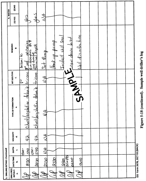

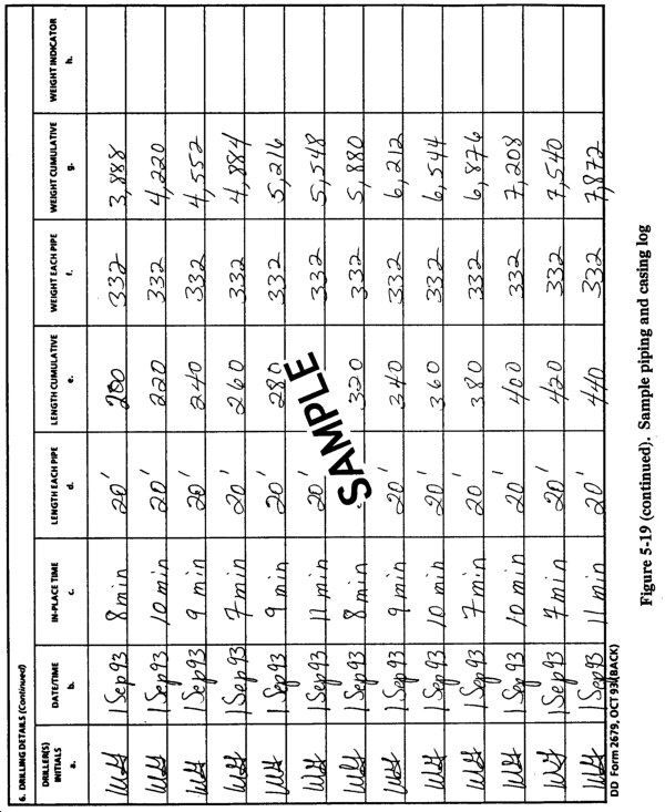
b. Soil Sampling. Try to obtain good material samples, and log the depth from which the samples came. Cuttings continuously wash to the surface during drilling. These cuttings are useful but are not the samples mentioned above. To collect a specific cutting sample, stop drilling and continue fluid circulation to wash most of the cuttings from the hole. When the hole is clean, advance the bit through the sampling interval and stop. Collect samples from the fluid of the drilled section. Resume drilling after taking samples. Redundant sampling impacts on drilling progress. However, collect several samples regardless of schedule impact to obtain worthwhile information. Field modifications of well design are often required, especially when subsurface information has been sparse. In most cases, the changes made during well drilling are minor. For example, placing a screen a few feet higher or lower to match the position of the most gravelly part of an aquifer, or adjusting a grout interval to match an impermeable layer above the aquifer.
|
NEWSLETTER
|
| Join the GlobalSecurity.org mailing list |
|
|
|