

Appendix E
Bits
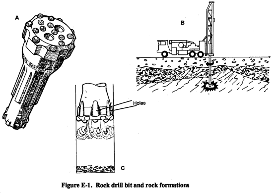
E-1. Maintenance. The rock drill bit (Figure E-1, A) is the least understood component in a drilling system. The parts of a drifter or down-hole drill undergo constant dynamic loading that can be accounted for with design. However, this is not true with the bit. Drilling in rock may mean a radical change of hard consolidated rock to a broken unconsolidated seam. The characteristics of rock--compressive strength, abrasiveness, and fracture pattern--are never consistent in either production or water-well drilling. Figure E-1, B shows drilling through various rock formations. Flushing passages (Figure E-1, C) must be well maintained and fairly deep to clean the hole. As the gauge of the bit is reduced by abrasive wear, many drillers forget to grind the slots deeper. Poor hole cleaning is a major cause of stuck drill string.
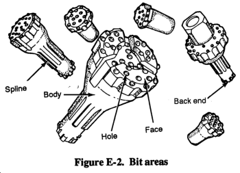
The following describes the areas to maintain on the bit for effective operation. Figure E-2 shows the areas described.
- Abrasion and poor hole cleaning will cause material around the exhaust hole to peen over. This action restricts the flow of air and causes even poorer hole cleaning. It is essential to grind exhaust holes open for best results.
- On down-hole drilling (DHD) bits, always apply grease to the spline before assembly in the chuck. On threaded bits, grease all shoulder and threaded areas.
- As a bit begins to wear, the face of the bit begins to look washed (worn away). The metal is washed at a faster rate than the carbide wears. The carbide should be ground until no more than 3/8 inch protrudes from the metal surface. If carbide is allowed to project further than 3/8 inch, carbide breakage is inevitable.
- Abnormal spline wear is usually caused by a worn chuck excessive feed force, or high RPM operation. By checking the bit for spline wear, you maybe able to prevent shanking of the bit, damage to the hammer, and loss of the hole.
- Although abnormal body wear or failure is not common in percussion drilling, check the bit body for fractures. By checking the body, you may prevent the loss of the bit in the hole. If barreling occurs, grind the bit body because the body of the bit should be kept in its original shape. Barreling results when a wear pattern occurs causing the diameter of the bit body to exceed the gauge diameter of the buttons.
- Check the striking end for excessive pitting. Pitting is usually caused by the presence of foreign material such as rock cuttings or use of rock drill oil with a high sulphur content. Drilling with a large amount of water may also accelerate corrosion on the striking end. A badly worn striking end is a sure sign that you should check the piston of the drill. Replacing the piston before breakage will usually save the cylinder.
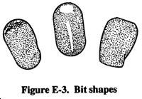
You should recondition the carbide insert or button (Figure E-3) to maintain its original shape throughout its useful life. Most bit failures involve carbide breakage or loss of carbide resulting from improper preventative maintenance or drilling practices.
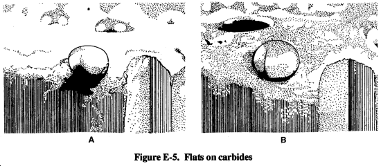
E-2. Failure. Carbide shear (Figure E-4, A) is the most prevalent type of carbide breakage. Tungsten carbide is very strong in compression, yet is relatively weak when placed in a tensile or shear mode. As the buttons begin to wear, they develop flat spots (Figure E-4, B). As these flats develop, the loading on the carbide begins to move from its basically vertical position or compression load to a horizontal position or shear load. This side loading or pinching (Figure E-4, C) of the carbide in the hole can ultimately result in carbide shear.
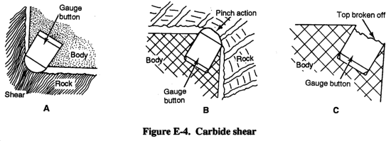
Figure E-5, A shows an overrun bit with severe flat spots. This condition will soon lead to button failure. Buttons must be ground to restore their original shape at the first sign of a developing flat. High rotation speeds tend to accelerate the development of flats on the carbide. Although RPM will vary with local conditions, rotating the bit faster will not increase the penetration rate but will increase the chances of shearing a carbide (Figure E-5, B).
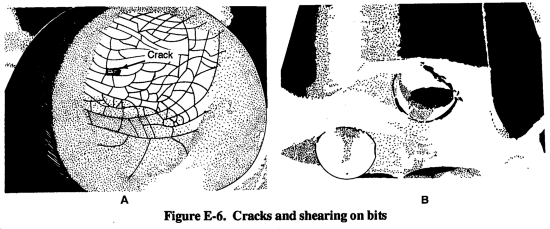
Progressive heat checking in the developed flats indicates excessive RPM. Small cracks (Figure E-6, A) develop on the face of the flat and if not reconditioned, breakdown of the button continues until it finally splits. The button then shears off and the effectiveness of the bit is lost (Figure E-6, B). A good rule of thumb is to rotate at the lowest RPM that permit smooth operation.
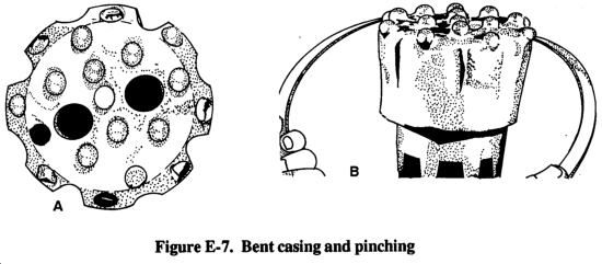
Another condition that can result in carbide shear is drilling through bent casing (Figure E-7, A). A bent casing will cause the carbides to be pinched as the drill string passes through it and the carbide breaks as a result. Also, when changing bits after starting a hole, do not put a larger bit into an existing smaller diameter hole. Always measure bit gauge and use the larger bit first to prevent pinching the gauge carbides (Figure E-7, B).
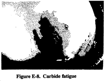
After many hours of drilling in nonabrasive soft rock the carbide begins to fatigue. A network of fine cracks appear and small flecks of carbide break away (Figure E-8). The buttons have a polished effect with no flats, and there is minimum abrasive wear on the bit body. If not checked, this will lead to further breakdown of the carbide, side loading, and carbide shear. To prevent this type of failure in soft formation drilling, reconditioning must be scheduled at intervals that do not exceed 10 percent of the overall life expectancy of the bit.
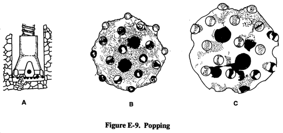
Popping of carbide inserts is a result of loose running. A carbide will pop clean from its socket if the drill string is not properly fed up in the hole (Figure E-9, A). This is most common in overburden drilling or in broken and unconsolidated formations. A large amount of energy is produced from the piston striking the shank in drifter drilling or the bit in down-hole drilling if the bit is not fed up to the rock. Instead of breaking the rock, this energy is retained in the bit and will cause the carbides to pop (Figure E-9, B). When body metal around the carbide becomes too weak due to overrunning the bit without proper grinding, the buttons pop out (Figure E-9, C). This greatly reduces the life of the bit.
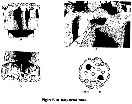
Body metal is another type of bit failure. Figure E-10, A shows a condition called body wash (eroded body metal). Figure E-10, B shows the lip next to the button and the extent to which the button is protruding. The combination of a flat carbide and a large beam of exposed carbide generates side loading which fatigues the base in which the button rests. Figure E-10, C shows that the carbide and body have separated just below the rim of the socket while a fatigue crack has developed in the body metal. Cracks in the body (Figure E-10, D) can lead to entire pieces of the bit shearing off.
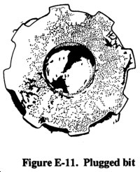
For optimum performance, introduce a bit to new rock regularity. If cuttings remain in the hole, the energy to break new rock is not transferred, putting undue stress on the bit, the drill, and the drill string. Each component will undergo more unnecessary stress and will fatigue faster and fail earlier. Figure E-11 shows an extreme example of what will happen if air is not continually fed down the hole. This bit has been plugged solid by the cuttings.
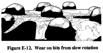
If rotation is too fast, flat spots, heat checks, and shearing will occur. If rotation is too slow, lopsided wear on the carbides will occur. Figure E-12 shows a bit that has been rotated too slowly. The button is barely out of the impression it made with the previous impact, when it is struck again. Undue wear is caused on one side of the button, creating a point on the carbide. When the point is sharp enough, it chips, or portions of the button break away.
E-3. Reconditioning. The following lists some suggested equipment necessary for proper bit reconditioning:
- A bit-grinding stand and a vitrified silicon carbide wheel that is 1 inch by 1 inch in diameter and rated at 25,000 RPM.
- An I-R DIR DG121 grinder or its equivalent.
- Safety glasses, hard hat, ear protection, and gloves.
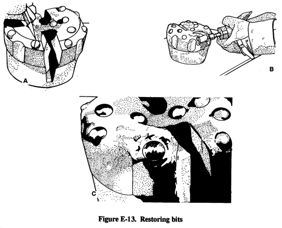
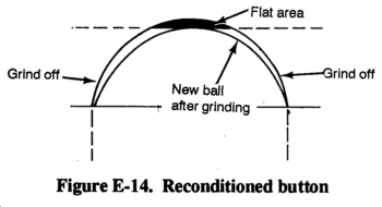
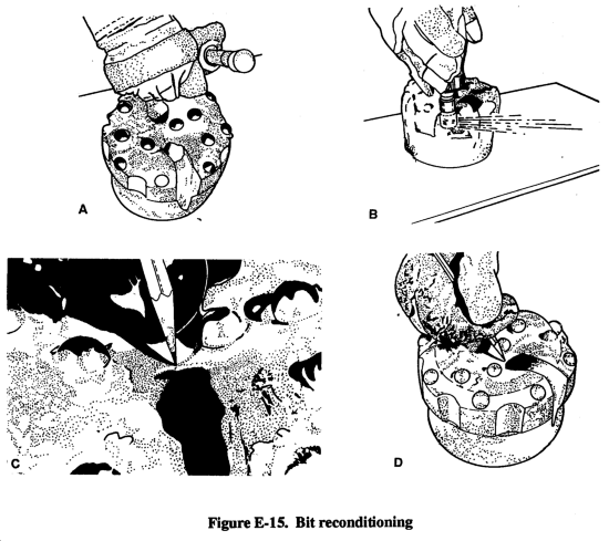
You must restore the original shape of the button when regrinding. To come close to this shape, draw a pencil line down the center of the flat on the gauge button (Figure E-13, A). Using the line as a guide, grind the button on both sides, but leave the pencil line untouched (Figure E-13, B). Leaving the pencil line ensures that the reground bit carbide will be concentric to the bit shank. (When concentric, the carbides carry an equal share of the load.) Also, leaving the pencil line prevents you from grinding away too much carbide, thus extending bit life. Finally, blend the untouched line area (Figure E-13, C). When finished, the button should look almost new. Figure E-14 is a diagram of a reconditioned button. Although gauge buttons receive most of the wear, grind all of the buttons, if necessary, (Figure E-15, A); grind the flutes (Figure E-15, B); check the blowholes (Figure E-15, C) and grind them back into shape (Figure E-15, D).
E-4. Rule of Thumb. In down-hole and drifter drilling, the most important factor contributing to poor performance and premature bit failure is operating the bit beyond the reconditioning point. A fixed guide outlining exact bit reconditioning intervals would be ideal. However, changing drilling conditions make the establishment of such a guide unrealistic. Therefore, establishing such intervals will ultimately be determined on the job. Consider the following recommendations:
- In hard abrasive rock recondition at the first sign of a flat on the button bit. A flat width should never exceed 1/4 inch.
- In soft or less hard abrasive formations, recondition before reaching 10 percent of the expected life of the bit. This prevents alligator-type failures and ensures proper bit life.
|
NEWSLETTER
|
| Join the GlobalSecurity.org mailing list |
|
|
|