Chapter 3
Field Operations
a. Commander. Well-drilling teams deploy to the field to construct water wells. These teams normally deploy with the organic equipment they use to drill and complete the well. Teams are manned for continuous operations and consist of two complete drilling crews, a mechanic, and a detachment commander. The detachment commander is usually responsible for--
- Training and care of team members.
- Care and maintenance of team's organic equipment.
- Support coordination with the supporting engineer unit.
- Deploying the team.
- Laying out the drilling site.
- Developing safety guidelines for the well-drilling team.
b. Driller. A drill team, which consists of a driller and two helpers, operates the drilling rig. A driller's responsibilities include--
- Operating and controlling the drilling rig.
- Establishing (and modifying when necessary) the drilling rate.
- Ensuring a proper mud mixture and sufficient volume.
- Sampling and monitoring the drill cuttings.
- Maintaining a driller's log of the well.
- Preventing accidents around the drilling rig.
c. Helper. A helper is responsible for--
- Making drill rod connections.
- Ensuring an adequate mud mixture during drilling.
- Maintaining and caring for the rig, tender, and tools during the drilling operation.
3-2. Team Planning, Coordination, and Preparation. A well-drilling team's primary responsibility in planning and preparing for a drilling operation is to maintain a state of readiness. They must train, practice, and discuss operations continuously. They should study information about specific sites and determine alternate solutions to potential problems. Periodically, teams should check each component of the well-drilling equipment. Team members must maintain drilling rigs and tender trucks in good operating condition. Before leaving for the mission area, teams should inventory all tools, parts, drilling accessories, and supplies.
Planning requirements to support Army well-drilling teams are similar to those needed for any augmentation team. Well-drilling teams do not have an organic headquarter. Well-drilling teams should be deployed and employed by an engineer headquarters capable of providing equipment, maintenance, administrative, and logistical support. Water wells are engineer construction projects and must be planned, researched, managed, inspected, and reported just as other projects are. The unit that the well-drilling team is attached to should provide the team with construction (field or tactical) standing operating procedures (SOP). The team should report well-drilling progress and procedures according to the SOP.
The well-drilling project should be managed by the critical-path method (CPM). The well-drilling-team's commander must coordinate and work closely with the construction or operation officers of the higher headquarters' unit to ensure timely researching and reporting. When well-drilling teams complete the well-drilling mission, they turn the well over to the operations officer (S3) for disposition. The team then moves to the next project. The S3 arranges transfer of the completed well, operating equipment, and technical specifications to a water-purification team, an installation, or a host-nation official.
Well-drilling teams will be in great demand in most TOs. Teams may not be able to return to a well site to perform repairs and keep up with the anticipated work load. The senior engineer will have to set priorities for the team's work schedule. He should include repairing existing and recently drilled wells in the work estimate. The senior engineer must also determine if the teams have the skills or equipment needed to repair the wells before filling a request.
The engineer unit's construction section, in coordination with the well-drilling team, should prepare a construction estimate to determine the needed support for the well-drilling operation. Team experience and land formations will dictate the length of a well-drilling operation. Staff personnel should consider the following when planning for the augmentation of a well-drilling team:
- Transportation of the well-drilling team's equipment and personnel by land, air, or sea, according to the unit movement books and operator manuals.
- Reconnaissance and route selection to mission sites.
- WDRT assistance and graphic products from the water-resources data base to select a potential drilling site.
- Security during movement and drilling operations.
- Earth-moving assets to clear and level the drilling site and excavate mud pits.
- Material handling equipment to offload well-completion-kit materials, as needed.
- Administrative support, including postal and legal services.
- Logistical support, including all classes of supply and arrangements for mess; petroleum, oils, and lubricants (POL); maintenance; and medical support.
- Delivery of the initial drilling water supply, if required.
- Turnover of the completed well to a water-purification team, installation, or host-nation official.
- Well-completion kit or component resupply.
- Communications support.
- Reporting procedures.
- Planning for the next mission.
3-3. Deploying Teams. Army well-drilling units are considered and organized as a specialized skill engineer team. They are not self-sufficient. These teams depend on an engineer battalion or a higher headquarters that is capable of providing support needed to accomplish the mission.
A well-drilling team leader must ensure that the unit the team is attached to understands the mission and capabilities of a team. Because a well-drilling team is small there is little redundancy and no surplus labor. The leader must request additional personnel needed to complete the mission. A well-drilling team has only the equipment necessary to drill under optimum conditions. A well-drilling team leader must request the following from the engineer unit:
- Transportation support of the equipment and personnel by land, air, or sea, according to the unit movement books and operator manuals.
- Routes to the proposed drill site.
- WDRT assistance and graphic products from the water-resources data base and an indication of where the TO commander wants the well.
- Security during movement and drilling.
- Clearing and leveling of the drill site.
- Excavation and maintenance of mud pits.
- Off loading and transportation of well-completion materials.
- Administrative support, including postal and legal.
- Logistical support, including all classes of supply with special emphasis on repair parts.
- Mess and potable water.
- Fuel and POL products and continual resupply.
- Specialized maintenance, evacuation, and on-site welding support.
- Medical support, including medical-evacuation (MEDEVAC) procedures.
- Initial water supply and resupply.
- Timely delivery of pea gravel for gravel packing material.
- Arrangements to turn over the completed well to the supported unit operations cell.
- Communications support.
- Reporting procedures.
- Resupply of completion-kit materials for next mission.
- Plans for the next mission.
3-4. Site Preparation. Most sites require some preparation before setting up the drill rig. In rugged terrain, teams may have to excavate into a hillside. They may have to prepare a drilling platform. Teams should always place the drill rig on stable, level ground. Where excavation is not expedient, teams may have to construct mat or timber platforms to level the rig.
CAUTIONAvoid setting the rig up on a fill area. |
DANGERDo not raise mast around electrical wires without a ground guide. |
NOTE: Historically, groundwater coming from its natural environment has been considered of good sanitary quality. Because of this, personnel in well drilling must understand the effects well drilling may have on the surrounding environment. Layers of rock and different formations protect the groundwater supply from contamination. Drilling a hole through these protective layers provides an access for bacteria and chemicals that could degrade water quality. Well drillers must take precautions to ensure that they will not contaminate the well and the aquifer.
Teams must level the site and clear it of obstacles and any potentially combustible materials. If overhead power lines area problem, teams must move the rigs or make previsions for removal of the power lines. The drilling platform (or drilling area) should be large enough so teams can safely operate each component during the drilling operation.
DANGERCheck for overhead power lines before moving a rig on site. |
CLEARANCES: If the power lines have a voltage of less than 50 kilovolts (kv), place the rig at least 10 feet from the power lines. If the power lines have a voltage of more than 50 kv, place the rig 10 feet plus 0.4 foot for every kv over 50 kv from the power lines.
NOTE: Consider all overhead power lines as being energized.
Teams should consider locations for the rig and mud-pit, working areas, and well-completion components and accessories; location for and access to drill pipe racks; and location and maneuverability of the tender truck. Teams should determine if they need a mud pit before starting the site preparation. If the drill rig does not have a portable mud pit or if the portable pit does not have sufficient volume, teams should construct a pit during the site-preparation phase.
3-5. Equipment. Current Army well-drilling and well-completion equipment consists of the 600-foot well-drilling system (WDS) that includes--
- A truck-mounted drilling machine.
- A truck-mounted tender vehicle.
- A well-completion kit.
The Army also uses the CF-15-S trailer-mounted 1,500-foot well-drilling machine and 1,500-foot completion kit. The 600-foot WDS replaced the CF-15-S trailer-mounted machine and 1,500-foot completion kit. However, the CF-15-S may still be found forward deployed for contingency purposes.
a. 600-Foot WDS. This system is used to support well-drilling requirements. The WDS can be deployed with minimal preparation and support equipment anywhere in the world. The WDS consists of--
- An LP-12 rotary well-drilling machine mounted on a NAVISTAR 6-by-6 truck chassis.
- A support vehicle.
- A lightweight well-completion kit (including accessories, supplies, and tools needed for drilling a well).
With the completion kit, drillers can complete a well to a depth of 600 feet using mud, air, or a down-hole hammer with or without foam injection. By adding an auxiliary air compressor and a drill pipe, the 600-foot WDS can drill to depths of 1,500 feet and accommodate the 1,500-foot well-completion kit. The well-drilling machine does not have to be modified when drilling with mud to 1,500 feet; however, additional equipment and more drill pipe are required to use the 1,500-foot well-completion kit. Additional equipment includes casing elevators and slips, larger drill bits, and 900 feet of additional drill steel. Well-drilling teams should ensure that they have the rig accessory kit for the LP-12 to be fully mission-capable. The 600-foot WDS is--
- Air-transportable.
- Equipped for air-percussion drilling and for rotary drilling with mud or air.
- Equipped to drill wells up to 600 feet.
- Adaptable for drilling to depth of 1,500 feet.
- Truck-mounted for mobility.
- A three-mode, water-transfer pumping system.
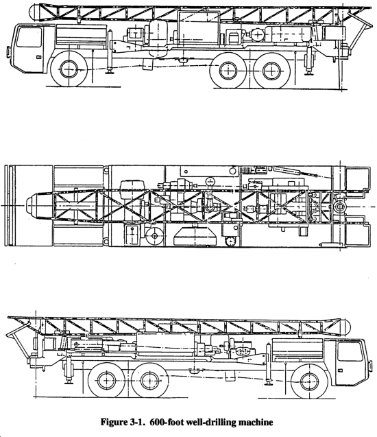
(1) Well-Drilling Machine. Table 3-1 lists specifications for the LP-12 machine. This machine is a truck-mounted, rotary well-drilling machine that has a 32-foot mast, 3-drum draw works assembly, rotary table, mud pump, and air compressor (Figure 3-1). The components are powered by the truck engine through a power take-off (PTO)(subdrive). A hydraulic system operates the leveling jacks, mast-raising cylinders, and breakout cylinders. The vehicle is equipped with attachments to tie down and lift the vehicle during transport. For operation and maintenance procedures, see TM 5-3820-256-10.
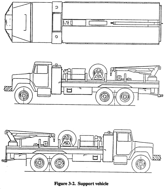
(2) Support Vehicle. Table 3-2 lists specifications for the support vehicle. This vehicle is truck-mounted with a 1,000-gallon water tank, a hydraulically driven water pump, an electric fuel pump and fuel-dispensing nozzle, a welder-generator assembly, and an electrohydraulic crane (Figure 3-2). The support vehicle has a storage area for transporting drill steel, pipes, collars, hand tools, and operating and accessory equipment for the drilling machine and the well-completion kit. The support vehicle provides hoisting, winching, pumping, welding, generating, burning, and storing requirements to support field drilling operations. Because of these provisions, additional equipment needs are reduced in a well-drilling operation. For operations and maintenance procedures, see TM 5-3820-256-10.
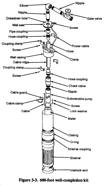
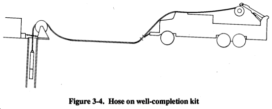
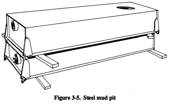
(3) Well-Completion Kit. This kit consists of equipment needed to complete a 600-foot well. It consists of polyvinyl chloride (PVC) well casing and screens, a submersible pump with starter, electrical wire, drilling mud, and cement for grouting the completed well (Figure 3-3). The completion kit is an expendable item. Teams use a collapsible drop hose to connect the pump with the surface. The hose is extremely lightweight and will not corrode in water (Figure 3-4). For instructions on using the kit, see TM 5-3820-256-10. The kit has a portable, steel mud pit, with internal baffling, that eliminates the need for a backhoe or similar piece of earth-moving equipment. This mud pit is designed to recover the drilling fluid that recirculates through the system. This mud pit is of limited size and requires frequent cleaning during a well-drilling operation (Figure 3-5).
(1) Well-Drilling Machine. Table 3-3 lists specifications on this machine. The CF-15-S is a compact, mobile drilling unit that can handle exploration and well drilling using air-rotary, mud-rotary, and down-hole-hammer techniques (Figure 3-6). The machine can drill to a depth of 1,500 feet and is equipped to use the 1,500-foot well-completion kit. The 600-foot well-completion kit may also be used with the CF-15-S to complete a shallow well. The drilling machine is powered by an 8-cylinder, 2-cycle diesel engine coupled to a PTO. Other major components include an air compressor, air-compressor drive, transfer case, auxiliary transmission, mud pump, mud-pump drive, subdrive assembly, rotary table, rotary-table transmission, and a 3-drum draw works.
An installed hydraulic system operates the leveling jacks, mast-raising cylinder, rotary-table cylinder, pulldown and holdback assemblies, and breakout trailer for mobility. Two lifting slings are welded to the frame. The sling lifting eyes are located adjacent to the four leveling jacks. The slings are used to hoist the entire drilling machine on board a surface carrier. The machine is equipped with a detachable mast for loading the machine on an air carrier. In addition, it is--
- Air transportable (C-130).
- Equipped for rotary drilling with mud, air, or foam circulation.
- Towable by semitrailer tractor or 5-ton truck (using a dolly).
(2) Well-Completion Kit. This kit is designed to support the CF-15-S well-drilling machine but may also be used with the 600-foot WDS (Figure 3-7). The kit is an assembly of machinery, hardware, and bulk material that is either used up in the drilling process or dedicated to the water well after the drilling is completed. These kits include the following items:
- A 6-, 8-, and 10-inch steel well casing to case the hole.
- A stainless-steel well screen.
- Drilling fluid.
- Submersible pump with pump cable and drop pipe.
- The pipe is capable of pumping 50 GPM at 1,245 feet.
- A 30-kilowatt (kw) generator.
- All necessary plumping to configure the well from the well screen to the pump discharge into a 3,000-gallon, portable, collapsible water-storage tank.
The kit has enough material to drill and complete a production water well in consolidated or unconsolidated formations anywhere in the world. These kits are maintained as depot war stocks until needed. Each kit weighs over 60,000 pounds. For a description of all components, see Supply Catalog (SC) 3820-97-CL-E01.
a. 600-Foot WDS. This system can be transported by three C-130s, two C-141s, one C-5, or by rail. A minimum amount of equipment disassembly is required.
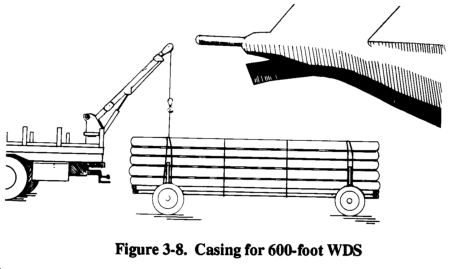
(1) C-130. The well-drilling team and the organic and support equipment require up to six C-130s for transportation. Support equipment includes a 5/4- and 5-ton truck with a 10-ton trailer. The well-drilling machine and support vehicles have roll-on, roll-off capabilities (Figure 3-8). The load configuration for transportation by C-130 is as follows:
- The well-drilling rig and two pallets of components and accessories are on the first aircraft.
- The support vehicle and one pallet of components are on the second aircraft.
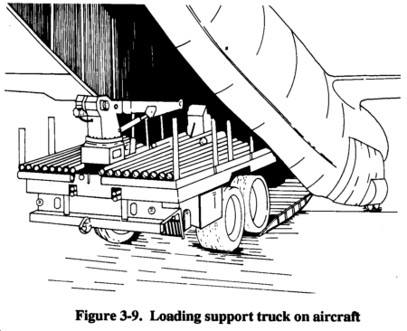
- The pipe dolly with two pallets of completion material is on the third aircraft (Figure 3-9).
(2) C-141. The WDS is transportable in a C-141 without any special disassembly, but parking shoring is required for the front axle of the drilling rig.
(3) C-5. The WDS is transportable in its operational configuration without any disassembly or special procedures.
(4) Rail. No special disassembly is needed to transport the WDS by rail. Also, the 6-by-6 truck chassis transports provide excellent road and cross-country mobility.
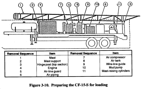
b. CF-15-S Drilling System. This system can be deployed by air, sea, or ground. The machine is not rapidly deployable by aircraft and requires extensive material-handling support equipment. Though designed for transport in a C-130, almost 12,000 pounds must be removed to meet a 13,000-pound weight restriction per axle in the aircraft. Figure 3-10 shows the components that must be removed from the rig for a C-130 transport. Loss of any of these items in transit will render the machine inoperable.
It takes about 6 to 8 hours to prepare the rig for loading and 10 to 12 hours to reassemble the rig. Because the rig must be partially disassembled, material handling equipment, such as a crone or forklift, must be available at the aerial port of embarkation (APOE) and aerial port of debarkation (APOD). The prime mover must be transported on a separate aircraft, which means that the mover may not be available at the forward airfield to remove the rig.
(1) Air. Six C-130s are needed to transport the CF-15-S drilling machine and completion kit. The CF-15-S rig is not transportable in a C-141. Even in the reduced weight configuration, the rig still exceeds the maximum allowable weight per axle. The machine may be transported by C-5s in its operational configuration without any special procedures or disassembly. See Technical Order (TO) 1C-130A-9 for specific loading instructions.
(2) Ground. For ground transportation, the kit requires 7 long-bed, 5-ton cargo trucks or 3 tractor-trailer trucks.
(3) Rail. For rail loading, the mast must be removed and secured to one flat car. The rest of the drilling machine is mounted on a second flat car.
3-7. Drill-Rig Setup. Before setup, teams must inspect the rig for damages during deployment. During the inspection, they should perform preventive maintenance checks. After inspecting the rig, setup can begin. Teams should use the following steps for the setup:
- Step 1. Position the drill rig. The rotary table should be over the center of the hole location. If you are using a portable mud pit, set the pit in position with the overflow pipe over the well location. Extend the rotary table (on the drill rig) to the working position, and move the rig, if required, to the final position. Set the rotary table exactly over the well or the mud pit overflow pipe.
- Step 2. Position and extend the leveling jacks. The jacks level the drill rig, remove the weight from the rig's suspension system, and provide a stable, rigid drilling platform. In soft soil, you may have to use timber under the jack pads to prevent the rig from sinking into the soil.
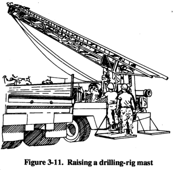
- Step 3. After extending the jacks, raise the drilling-rig mast (Figure 3-11). Check for overhead obstructions or power lines. Periodically, release the hoisting drum and auxiliary drum brakes to allow slack in the cables. After fully raising the mast, lock it into position and recheck the drill rig's level.
- Step 4. Check and, if necessary, connect the discharge piping. Depending on the type of drilling operation, connect either the air compressor or the mud pump to the standpipe on the mast.
- Step 5. Install or dig a mud pit, whichever is applicable. Make the appropriate connections to the mud pump to ensure continuous cumulation of the drilling fluid.
DANGERBefore drilling, check the area |
DANGERYou must wear hard hats or |
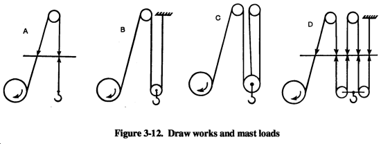
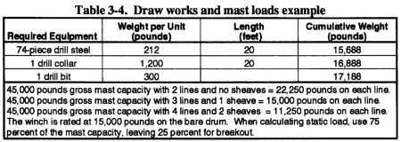
When drilling past 600 feet, the kelly draw works must be rigged with a double block to create a three- or four-part line (Figure 3-12). Using the sheave block provides a mechanical advantage that allows heavier weights to be lifted. By using sheaves, the load is supported by two or more lines. This provides two or three times the tensile strength used to hold the load. Also, using more lines allows the winch to pull on the first layer of the cable on the drum, which increases the capacity and saves wear on the chains. Table 3-4 is an example of Figure 3-12. For more information on drill-rig setup, see the operator's manual for the drilling system you use.
DANGERYou must wear protective eyeglasses and protective |
3-8. Drilling Fluid. If you use rotary drilling with mud, connect or place the suction line of the mud pump in the mud pit and fill the pit with water. Close the standpipe valve and prime the mud pump. Mix the drilling fluid in the mud pit by slowly circulating fluid through the mud pump and adding drilling mud to the mixing hopper (Figure 3-13). The drilling fluids usually used for mixing mud are a Wyoming-type bentonite drilling additive (Quick-Jel) or an organic or inorganic polymer fluid (Revert or E-Z Mud). Mix the additives until you reach the desired weight and viscosity for the drilling mud. Chapter 5 details mud mixing.
3-9. Well-Drilling Operations. Before you start drilling, you must select a drill bit. Consider the well diameter and the type of formations you will drill through. The types of bits are--
- Drag bits. Use these bits for soil, unconsolidated materials usually found near the surface.
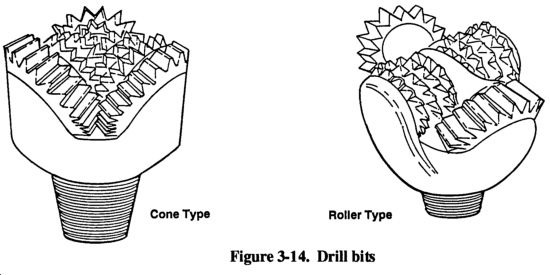
- Tricone roller-rock bits. Use these bits for a variety of materials from soft formations through hard rock (Figure 3-14). The bits are available in different degrees of hardness. Bits used for softer formations have longer teeth on the roller cones.
- Down-hole hammers. Use these bits for very hard rock. Rarely will you use this bit to start a borehole.
a. Starting the Operation. The first operation is spudding in (starting the borehole). Before you start drilling the actual hole, consider drilling a 6- to 71/2-inch test hole. Doing so will ensure that you dig the larger hole straight, and you should locate the aquifer quicker. Use the following steps to start the drilling operation:
- Step 1. Make up the drill bit on the kelly and lower the bit to the ground.
- Step 2. When the bit contacts the ground, engage the rotary table and clutch to start drilling.
- Step 3. After the borehole advances 6 to 12 inches, engage the mud pump to start circulating the drilling fluid (which will be mud or air).
- Step 4. After drilling down the kelly, stop the rotation and raise the kelly about 4 inches off the bottom of the borehole. Circulate the drilling fluid until all drill cuttings are removed.
- Step 5. Disengage the mud pump, raise the kelly, and remove the bit.
b. Finishing the Operation. After spudding in, use the following steps to finish the operation:
- Step 1. Makeup the bit on a drill collar. Suspend the collar and bit in the borehole using the hoist or sand line. Support the drill collar in the hole using slips.
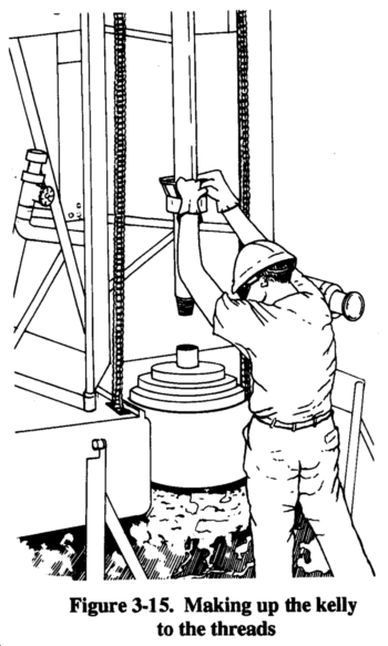
- Step 2. Clean and lubricate the threads on the kelly bar and makeup the kelly to the threads (Figure 3-15).
- Step 3. Remove the slips, and lower the kelly so that the drive bushing engages the rotary table and that the tool string is lowered to the bottom of the borehole.
- Step 4. Engage the mud pump again and continue drilling. After drilling down the kelly, circulate the drilling fluid until the cuttings are removed. Raise the tool string until the tool joint is 4 to 6 inches above the rotary table.
- Step 5. Disengage the mud pump and set the slips to support the tool string. Disconnect the kelly from the string and set the kelly back to the cradle position.
- Step 6. Run out the sand line, remove the end cap, and connect a hoisting plug to another drill collar or to a joint of drill pipe.
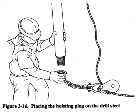
- Step 7. Lift the drill steel with the hoist line or sand line and place the hoisting plug on the drill steel (Figure 3-16).
- Step 8. Remove the lower end cap. Clean and lubricate the threads. Make up the threads to the string in the hole with pipe wrenches.
- Step 9. Lift the entire string slightly and remove the slips. Lower the string until the tool joint is 4 to 6 inches above the rotary table and the slips are reset.
- Step 10. Make up the kelly to the tool string, remove the slips, engage the mud pump, lower the string to the bottom of the borehole, and continue drilling. Repeat the process until you reach the desired depth.
- Step 11. Reverse the process to come out of the borehole.
Finally, if the drill rig breaks down or needs repair or maintenance, record the information in the log. The information in the driller's log can provide you with an insight into local conditions and help you determine well-screen locations and plan for additional or future well installations. Always place the screen sections into the aquifer and not at the bottom of the hole.
WARNINGTo prevent injuries from shifting loads, use taglines when hoisting a load. Attach long taglines to the load to maintain control. |
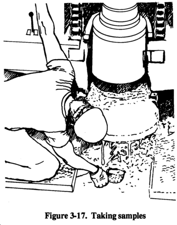
3-10. Sampling and Logging. You should take samples and record them on every well drilled. During the drill operation, take samples of the cuttings in the drilling fluid (Figure 3-17). Record the samples in a driller's log according to basic classifications (sand, clay, or granite) and describe their color and consistency (coarse or free) when possible. Also, record the approximate depth of the sample. If you want samples from a specific depth, stop the drilling operation and let the drilling fluid circulate until the cuttings reach the surface.
Other information you should record are advance rate, reaction of the drill rig, any loss of circulation, and changes in drilling fluid consistency. Periodically, check the drilling fluid for viscosity, weight, and sand content. Log the test results and any adjustments you made.
Depending on the construction method, set the well casing in the well before or at the same time as you set the well screen. (The 600-foot WDS has no surface casing.) If the borehole has a tendency to cave in during drilling, install the casing while drilling but before reaching the desired depth. (Use this procedure when drilling in loose, unconsolidated materials.) When installing the casing before the well screen, such as surface casing, the casing must be larger than the screen. Therefore, use a larger drill bit than the one used to complete the screen portion of the borehole. The decision to use surface casing should be made before mobilizing and should be based on the geologic information about the site.
a. Surface Casing. Use the following steps to install the surface casing:
- Step 1. Drill the borehole to a predetermined depth, and remove all the cuttings by circulating the drilling fluid. Withdraw the drill string and remove the bit.
- Step 2. Set the kelly back in the cradle. Connect the elevators to the first section of surface casing that is lifted over the borehole by using a casing elevator and the hoist or by using a sand line (Figure 3-18).
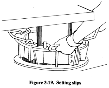
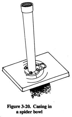
- Step 3. Lower the casing into the well and set the slips (Figure 3-19), which suspend the casing in the well, in the spider bowl (Figure 3-20).
- Step 4. Disconnect the elevator. Hoist the next casing section with the elevator, and place it in the first section. Join the two sections. Slightly lift the string of casing, and remove the elevator from the lower section. Lower the casing, and repeat the process until you suspend the last casing section in the well.
- Step 5. Grout the casing in place with a cement grout. After the grout sets (about 24 hours), resume drilling operations using a drill bit that will fit inside the surface casing. Drill the well to the desired depth, and case and screen the lower section of the well, using the single-string method.
b. Screening. You can use the following method to install screens:
- Step 1. Place a casing section in the well. Cap the casing on the lower end so materials from the bottom of the well will not enter the well.
- Step 2. Suspend a screen section over the well and attach the screen section to the casing section.
- Step 3. Lower the screen and casing section. Suspend them in the well either by the elevator resting on the rotary table or by slips in the spider bowl.
- Step 4. Add casing until the screen reaches the desired depth.
Chapter 5 discusses other methods of screening.
c. Filtering and Backfilling. The last procedure when installing screen and casing is to place a gravel-pack filter around the screen and backfill material around the casing. If you place the screen in material such as gravel or very coarse sand, you may not need a gravel pack. Place the gravel filter material around the outside of the casing. Deposit the material to the bottom of the well. Add gravel to about 5 feet from the top of the screen. (Use the sounding method to determine the level of the gravel.) Add impervious backfill around the casing from the gravel pack to about 10 to 20 feet from the surface. If you use grout instead of impervious material, add a couple of feet of clay above the gravel to prevent the grout from entering the gravel filter. Bring the grout to the surface.
3-12. Well Development. Frequently, when a well is first installed, the efficiency (production per foot of drawdown) is not satisfactory, and you must develop the well either by pumping or surging or both. Developing a well removes the remaining drilling fluid, breaks down any filter cake buildup on the borehole wall, and flushes the fines in the formation (adjacent to the grovel pack) into the well. Make sure that you pump the well of all fine sediments and sand with an airlift before installing the submersible pump. If you do not, the pump and components will wear out prematurely. To develop a well, pump or blow the drilling fluid out of the well. Agitate the water in the well to produce an alternating in and out flow through the well screen (or gravel pack). There are several methods available to develop a well. The simplest method follows:
- Step 1. Attach a weighted plunger or surge block to the sand line. Lower the surge block into the well below the water level but above the screen.
- Step 2. Lift the block and then drop the block 3 to 4 feet, repeatedly, to surge the well. Continue this action for several minutes.
- Step 3. Remove the surge block and lower a bailer into the well. All of the sand that was pulled into the well is bailed from the sand trap.
- Step 4. Repeat the process, noting the amount of sand brought into the well each time. Development is complete when 5 milligrams or less of sand per liter of sampled water is removed.
- Step 5. Sanitize the well with calcium hypochlorite.
3-13. Sanitary Seals. All wells must have a sanitary seal to prevent contamination from surface runoff. Mix cement grout and place it in the annulus between the well casing and the borehole wall. Extend the grout from the surface to the top of the backfill material (30-foot minimum). You should also pour a concrete platform (about 4 feet by 4 feet) around the casing at the surface with the casing extended at least 1 foot above the surface. The upper surface of the slab and the surrounding area should be gently sloping away from the well for better drainage. In addition to a surface grouting, you need to install a well seal (a type of bushing or packing gland) to prevent foreign materials from entering the inside of the well casing. You normally install the well seal when you install the pump, which is after you complete all development, testing, and disinfecting.
3-14. Pumping Tests. After installing a well, you should perform a pumping test. The test will show you if the well can produce the required amount of water. If the well is considered permanent, the pumping test should help you evaluate any future performance deterioration. Evaluation parameters are flow rate, time, and drawdown in the well.
Before you start the test, place a sounding device, such as an M-Scope, in the well to measure the water level during the test. You must also measure and regulate the flow rate during the test. The most proficient way to measure the flow rate is with a flow meter. However, you can use a calibrated container and a stop watch. Use the following procedures to perform the pumping test:
- Step 1. Temporarily install a pump in the well below the anticipated drawdown depth but above the screen.
- Step 2. Measure the static water level and start the pump. During the test, one team member should monitor the flow rate and try to keep the flow rate constant.
- Step 3. Record the drawdown with the flow rate. Take early readings quickly; then spread out the readings as testing progresses. An ideal reading schedule would be the initial reading and then a reading at 30 seconds, 1 minute, 2 minutes, 4 minutes, 8 minutes, 15 minutes, 30 minutes, 1 hour, 2 hours, and so forth. You must record the exact times you take readings of the drawdown and flow-rate measurements. The length of a test usually depends on the purpose of the well, the urgency for water, and the time available. On small water supplies, you can perform an adequate evaluation in 4 to 5 hours. For large, permanent supplies, tests could take from days to weeks. The GPM, footage of drawdown, and available drawdown give an immediate indication of the well's capacity. If the pump from the well-completion kit is capable of producing more water than the well can, you should put a throttle or a valve on the pump. Doing so will help regulate water extraction and will prevent pump damage.
- Step 4. Set and adjust the pump. The well is now ready for use or for connecting to a treatment, storage, and distributions system.
|
NEWSLETTER
|
| Join the GlobalSecurity.org mailing list |
|
|
|


