| Chapter Seven. Bulk-Fuel Storage Facilities |
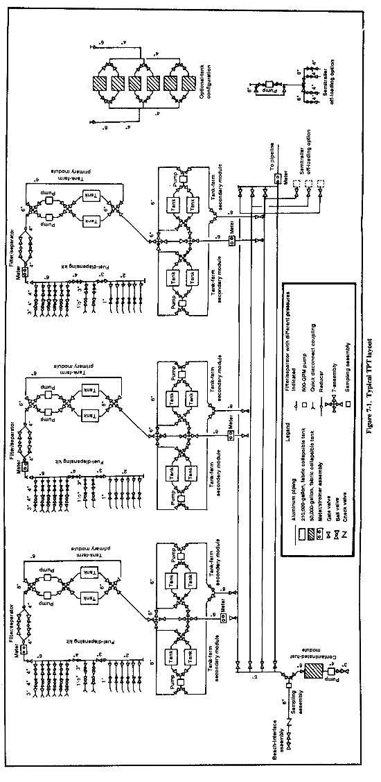
7-1. Tactical Petroleum Terminal. The TPT is the Army's bulk-fuel storage facility. It is a fuel-handling system designed to receive, store, and issue bulk petroleum fuels, specifically diesel and jet fuels, The TPT serves as a base terminal in an undeveloped theater and can be used in the developed theater to supplement existing facilities that are inadequate or damaged. The TPT can store up to 1,080,000 gallons of fuel in each of its three fuel units. Each fuel unit can be dedicated to a specific type of fuel. The six optional 50,000-gallon tanks increase the system's capacity. Fuels can be received from a pipeline or from tanker vehicles. The TPT can dispense the fuel directly to user vehicles, but it usually limits issue to bulk-fuel transport vehicles. The TPT can also return fuel to the pipeline for distribution downstream. The system can receive fuel at a rate up to 800 GPM. Each fuel unit can issue fuel at rates up to 600 GPM. Figure 7-1 shows a typical TPT layout, including separate dispensing areas for different type fuels. The major components that make up a TPT are--
- Eighteen 210,000-gallon fabric tanks.
- Six 50,000-gallon fabric tanks.
- Fifteen 600-GPM pumps.
- One 350-GPM pump.
a. Responsibilities. The theater support command is responsible for specifying the capacities and general locations of bulk-storage facilities. The petroleum group within the support command is tasked to develop, design, and construct the petroleum distribution and storage facilities based on the operational plan of the theater commander. The quartermaster petroleum/lubricant (P/L) company is responsible for installing fabric tanks. Fabric tank farms require a large, flat area for construction. Engineers are responsible for the earthwork at the TPT site, which includes constructing tank pads, earth berms, and roadways. Tank-farm locations must be cleared and leveled, and all tanks should have a berm around them to protect them from enemy fire and to retain the contents if the tanks rupture.
b. Terminals.
(1) Base Terminals. Base terminals serve ports of entry and provide initial storage of petroleum products in a TO. These terminals are in rear areas, at or near ports of entry, or at other tanker loading and unloading points. A TO may have more than one base terminal. The base terminal is generally the largest bulk-fuel installation of the pipeline system. In an undeveloped theater, the TPT may serve as a base terminal. The base terminal should be large enough to--
- Provide storage for unloading, within 24 hours, the full cargo of the largest tanker that may be scheduled.
- Provide storage for reserve supplies of each fuel to be carried through the pipeline or dispensing lines fed by the tank farm.
- Have enough reserve operating capacity so that products can be received and issued at the same time.
- Have enough capacity to allow fuel received from a tanker to settle at least 24 hours before it is pumped through the pipeline.
(2) Intermediate Terminals. These terminals serve as reserve-storage and dispensing installations. The location and size of the terminals depend on the capacity of the pipeline system, the nature of the pumping operation, and the tactical situation. There should be enough storage capacity to receive and issue fuel at the same time. Intermediate terminals will be located, at a minimum, after every fifth pumping station. This will allow the quartermaster operating unit to coordinate pumping-station activities.
(3) Head Terminals. These terminals may be located in the main supply areas of an independent corps. Tanks at a head terminal may be either fixed or fabric, depending on the pipe head location, the needs of the troops, and the tactical situation.
(a) Fixed. The pipe head is usually a fixed installation that services a group of airfields in the TO's rear area or Class III supply points only. A fixed installation may include head terminals or branch lines, storage tanks, tank-truck loading facilities, tank-car loading and unloading facilities, and can-and-drum filling stations.
(b) Portable. The pipe head is portable when it is in the corps' supply area because it may have to move with the forward supply points every few days. As a rule, portable tank-farm facilities are used for storage. Forward petroleum supply facilities may be supplied by hose lines from this portable storage. Tanker vehicles may be used with the portable tanks to increase storage.
c. Regulating Facilities. Any excess tanks at a terminal may be used as a regulating facility. The extra tanks are used to store reserve fuel. When a break occurs in a line, pumping is stopped in the damaged section. The fuel at the regulating facility downstream from the break is pumped instead. This confines breaks to one point in the pipeline and allows pumping to continue during repairs. Regulating facilities should have the capacity to store enough fuel to continue pumping operations for six hours.
d. Tank Farms. A tank farm is the main component of a pipeline terminal. It is a group of collapsible fabric tanks connected by pipelines. The pipelines in the tank farm are joined so that products can be moved into, out of, and between storage tanks. Military tank farms are complete installations made up of various facilities, operation buildings, and security fences. A tank-farm size depends on the needs at the particular terminal. Standard tank farms listed in AFCS are in the following barrel capacities: 50,000; 100,000; 150,000; 200,000; and 250,000.
(1) Complexes. If more than a 250,000-bbl storage capacity is needed at a single terminal, two or more tank farms are installed to provide enough storage. These tank farms are connected by a central switching manifold. Each group of tank farms is a tank-farm complex. The tank farms in each complex should be spaced at least 4 miles apart. Each tank farm is usually supplied by two branch lines joined to two incoming trunk pipeline. Booster stations are placed in each branch line to provide the needed line pressures for proper flow to the switching manifold. Standard tank-farm complexes are normally in barrel capacities of 400,000; 600,000; 800,000; and 1,000,000.
(2) Portable Facilities. Standard, portable tank farms are installed where portable storage is needed. Portable tank farms have 10,000-; 20,000-; 50,000-; or 210,000-gallon collapsible tanks and the equipment needed to connect them to the main line. The capacity of the tank farm depends on the size and number of collapsible tanks.
(3) Collapsible Fabric Tanks. These tanks come in 3,000-; 10,000-; 20,000-; 50,000-; and 210,000-gallon capacities. The tanks require large, flat areas that engineers construct. Eighteen 210,000-gallon fabric tanks makeup a complete TPT. Because they are easy to install, fabric tanks have made steel tanks obsolete.
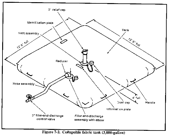
(a) 3,000-gallon tank (Figure 7-2). The primary use of this tank is to provide fuel for mainline pumping-station operations. The tank is made of coated nylon. It has a 3-inch fill-and-discharge assembly. The tank is about 13 feet square and 6 feet high.
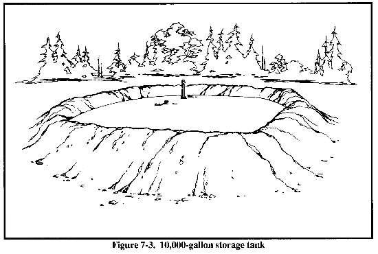
(b) 10,000-gallon tank (Figure 7-3). Two types of this tank exist in the Army inventory: the square and the rectangular models. They are used for temporary storage and for dispensing tanks at portable, pipe-head tank farms. These tanks may be used in the fuel-system supply point. Both models are made of coated nylon. They have positioning handles, a fill-and-discharge assembly and fittings, a pressure-relief assembly, and a drain assembly. Each tank has a 4-inch manifold assembly with fittings and a repair kit. The square tank is about 20 feet square and 4 feet high. The rectangular tank is about 40 by 11 feet and 4 feet high.
(c) 20,000-gallon tank. This tank is primarily used in the fuel-system supply point. The tank is issued as a single item of equipment for additional bulk storage. It is made of elastomeric-coated nylon and has 12 carrying handles, two 4-inch filler/discharge assemblies with access doors, a vent-fitting assembly, and a drain-fitting assembly. When filled, the tank is about 28 by 24 feet and 5 feet high.
(d) 50,000-gallon tank. This tank is used for initial storage at beachheads and for storage along trunk hose-line and pipeline systems. It may be used for storage at fixed supply installations and airfields until permanent tanks can be built. This tank is made of lightweight, single-ply, rubber-coated fabric. Each tank has two 4-inch combination inlet and outlet connections, a 2-inch combination overflow and vent fitting, and a 1/2-inch drain plug. Tank accessories include a manifold assembly with half valves and couplings and a clamp kit, D-rings, and gaskets. The tank is about 65 by 25 feet and 5 1/2 feet high when filled.
(e) 210,000-gallon tank. This tank, also called a bulk-fuel tank assembly (BFTA), is primarily used for initial storage at beachheads as an integral part of the TPT tank-farm complex. Other than size, the 210,000-gallon tank resembles the 50,000-gallon tank in appearance. It has two 6-inch combination inlet and outlet connections and a vent tube on top. When filled, the tank is 70 feet square and 8 feet high.
e. Site Criteria. Tank farms must be located in the area that they are to supply. The general location is designated by the petroleum group, which is responsible for the design, construction, and operation of the distribution system. Site selection is relative to the location of Class III supply points and transportation routes, whether by pipeline, tanker truck, barge, or rail tank car. The specific location may have to be modified due to site constructability.
The engineer unit tasked to the construction site must work closely with the petroleum group in exact layout and placement of the tank farm. The selected sites should be in noncongested areas where other facilities do not interfere and where sabotage and sneak raids are relatively easy to defend against. Tank farms should never be located in drainage areas above critical installations. Site tank farms so that a tank-farm fire will not spread to other supply areas or installation areas. The tank-farm site should have as many of the following features as possible:
- Adequate road and/or rail facilities for transporting pipeline and tank-farm equipment and supplies.
- An area large enough for proper tank dispersion and expansion of the tank farm. This is a major factor when collapsible fabric tanks are used because of the large area required.
- Absence of distinctive landmarks or terrain features that could aid enemy aircraft in locating and identifying the site or could be used to adjust artillery fire.
- Terrain that allows tanks or groups of tanks to be separated b y terrain masses to minimize damage due to the blast effects of atomic weapons or other large effect munitions.
(1) Hydraulic Design. Try to choose a site that gives the minimum required suction pressure by gravity flow from the outlet of the lowest tank to the intake of the pipeline pumping station that is to pump from the tank farm. The pressure should be at least 20 psi.
(2) Topographic Features. The best sites are on flat ground in sloping terrain with adequate natural cover and concealment. This allows for gravity flow to the first pumping station and isolates tanks for damage protection. Beachhead sites may be located in sandy seashore areas up from the beachline and on old harbor terraces. Desirable inland sites may be situated on bench terraces along valley borders or at points on a terrace where a small stream or gully cuts through.
(3) Soil Conditions. The site should have adequate drainage. Preferably, the water table should be more than 6 feet below the surface. Avoid marshlands, riverbanks, or bottomland subject to flooding and other sites with poor or undependable drainage.
f. Flexible Hose Lines. These hose lines are available in various lengths, diameters, and strengths, depending on their use. Low-pressure hoses are used for moving fuel inside petroleum-storage facilities. They are also used during the assault phase of a military operation when the advancing elements push forward more rapidly than metal pipelines can be constructed.
High-pressure hoses, as part of the OPDS, move fuel from ship to shore, replacing the need to weld and install an underwater pipeline.
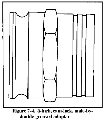
(1) 6-Inch, Cam-Lock, Male-by-Double-Grooved Adapter. This adapter (Figure 7-4) is used in the tank-farm assembly. It is connected to the hose that goes to the elbow coupler on the tank inlet.
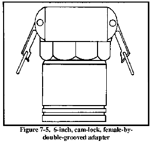
(2) 6-Inch, Cam-Lock, Female-by-Double-Grooved Adapter. This adapter (Figure 7-5) is used in the tank-farm assembly. It is connected to the cam-lock gate valve on the discharge line leading to the 210,000-gallon, collapsible, fabric tank.
(3) 6-Inch, Bolt-On-Type, Hose-to-Cam-Lock, Male and Female Adapters. This device is installed on the ends of the 6-inch hose-and-reel kit. It is available in male and female configurations.
(4) Cam Lock. This is a quick connect fitting found on valves and hoses in the TPT and low-pressure areas of pumping stations. The cam lock is a low-pressure connection with a MAWP of 150 psi.
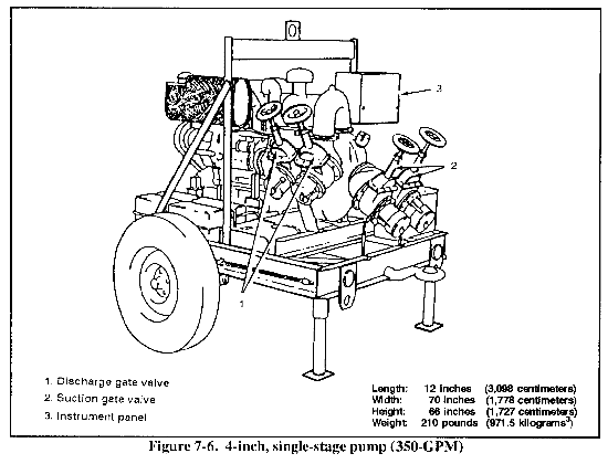
h. 4-Inch, Single-Stage, 350-GPM Pump. This unit (Figure 7-6) consists of a 3-cylinder, 4-stroke, diesel-engine power unit and a single-stage centrifugal pump. This pumping unit is designed for use with the contaminated-fuel system for loading out or transferring contaminated fuel, but it can be put in general utility service as necessary. Operating at 2,300 RPM, the unit will pump 350 GPM with 275 feet of head.
i. Filter Separator. The filter separator is frame-mounted in the pipeline manifold between the pump and the loading rack of all dispensing facilities. It is used to remove entrained solids and to free water from the fuel before the user receives it. Free water may be present in the fuel in two forms, in a fine dispersion or in large slug quantities. The filter separator passes the contaminated fuel through a series of filter/coalesce elements. These elements may be constructed from various combinations of fiberglass mat or cloth; paper and nylon, dacron, cotton, or wool cloth, as long as the elements meet the performance specifications outlined in MIL-F-52308. The entrained solids are caught and held by the fibrous material, and the water is coalesced into large drops. Because water and fuel have different specific gravities, the waterdrops fall to the bottom of the filter/separator vessel and forma pool. The 15-, 50-, 100-, and 350-GPM filter separators are equipped with a water-level sight glass and a manually operated valve to drain water from the sump.
The pump unit is mounted to the front portion of the skid frame and is attached to the engine bell-housing and flywheel. The suction and discharge assemblies are mounted to the pump body. The unit is a single-stage, centrifugal pump that is self-priming after an initial filling. The pump body and volute are a one-piece aluminum casting with a 6-inch suction port at the front of the pump body and a 6-inch discharge flange at the top of the pump body.
The bronze alloy impeller is enclosed in the close-fitting volute of the pump body. Replaceable wear plates in the pump body take most of the internal pump wear. The impeller is secured to the end of the impeller shaft. The impeller shaft, coupling assembly, shaft seal, and bearings that support the impeller shaft are contained in the bearing housing. The pump body is fitted with a 1 l/2-inch priming port with a quick-disconnect, cam-locking, male coupling. The coupling has a cam-locking dust cover secured to the pump body by a short length of chain.
7-2. TPT Site Selection and Earthwork.
a. Site Selection. The P/L company is responsible for TPT site selection. When choosing an exact site location, a construction engineer should be present to evaluate the constructability of the site. The P/L company should consider the following factors in site selection:
(1) Area. The site must be large enough (about 40 acres) to contain the required equipment and roadways. Flexibility is important when setting up the area.
(2) Terrain. The site selected should be reasonably level and well-drained, especially where equipment is loaded, unloaded, and stored. The P/L company should consider the following when selecting the terrain:
- Low, swampy areas. Try to avoid such areas.
- Large rocks and trees. The area should have as few of these as possible.
- Earth-moving equipment. Determine how much is needed to accomplish the mission.
(3) Road Access. If possible, the site should be located relatively close to existing road systems that can carry the traffic involved. The road system must be accessible or a new road will have to be built to connect the existing road systems.
(4) Water Availability. If possible, water should be available at the site. If none is available, it should be brought in. Water availability is a safety factor. Water must be available for charging the aqueous film-forming foam (AFFF) on a wheel-mounted fire extinguisher, for general fire protection, and for personnel safety.
(5) Local Population. The site should be well away from local population concentrations.
(6) Plot Plan and Site Investigation. After the P/L company selects the site, they should--
- Make a preliminary plot plan showing all the major equipment and system locations, including tanks, pumps, fuel-dispensing areas, tanker-truck receipt areas, access roads, and pipeline route into and out of the site.
- Make primary cuts and fills so details of the site's characteristics can be seen before starting earthwork on tank sites, berms, and roadways.
- Review the preliminary plot plan and correct it as needed.
- Make a final plot plan indicating permanent equipment locations.
- Construct final roadwork and tank pad and berms, based on the final plot plan.
b. Earthwork. Earthwork requirements at TPT locations are tank berms and pads, roads, and culverts. This work requires the support of an engineer unit, normally a combat heavy engineer battalion. Earth berms are constructed around POL tanks to protect them from enemy fire and to retain the contents should the tanks rupture or catch on fire. The size or height of the berms should be such that the volume of liquid in the tanks can be contained within the berms should a rupture occur. Once a site is selected, do the following for a fabric tank farm:
- Clear the site and grade about a 1 percent slope towards the tank drain assembly. Remove any sharp objects that could puncture the fabric tank.
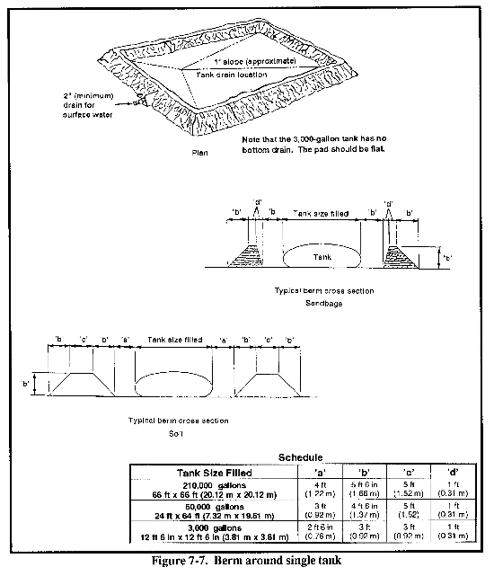
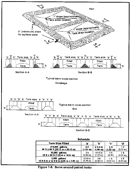
- Construct berms around single or paired tanks from the surrounding area (see Figure 7-7 and Figure 7-8).
- Place a berm basin drain at the lowest end of the tank pad. The drain is a pipe (2-inch diameter minimum) with a gate valve. Place this pipe under the berm during construction.
- Add 1 foot of height to the berm, as a safety factor. The berm should extend above the top of the tanks and be at least 4 feet wide at the crown. The walkway between a tank and berm should only be wide enough to allow for maintenance.
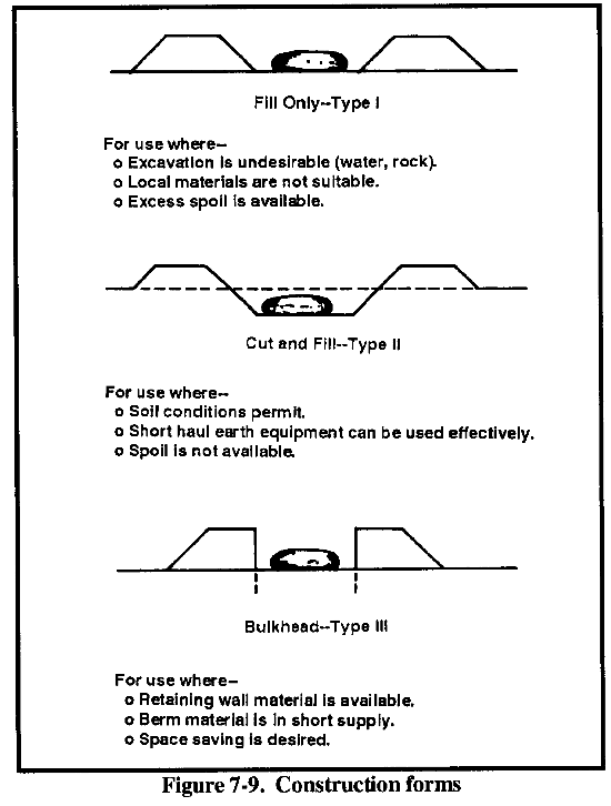
The type of earthwork construction depends on the site conditions and available materials. There are three general forms of construction (see Figure 7-9). A berm entirely above ground allows for rainwater drainage but is the least desirable because it must be made of fill. A maximum amount of earth must be hauled to the site, increasing time and expense. When possible, you can minimize the time needed for moving soil by equating the volume of the cut with the volume of fall, as closely as possible.
c. General Site Preparation. Site selection and preparation and earthwork must be based on the plot plan that the terminal-operating unit prepare. Again, flexibility is important between using the plot plan and preparing the site. Consider using the following procedures:
- Base site preparation work on a grading plan that minimizes cut and fill operations even if the plan is roughly prepared in the field.
- Base the plan on actual on-site elevations and survey, obstructions, and knowledge of the types of soils that appear to be present.
(1) Cut an Access Road. Cut an access road, unless one already exists.
(2) Stake out the Area. Stake out the area that must be cleared, marking areas where the major components will be located. Cut, grub out, doze, or blast out major obstructions such as trees, bushes, large rocks and boulders, and buildings.
(3) Clear the Area. Clear and grade the areas where fuel tanks will be located, transfer systems installed, roadways built, and loading and unloading facilities installed. You do not have to clear and grade the entire area required for a TPT. Make sure you allow for good drainage from the site.
(4) Cut and Fill. When possible, plan and execute cuts and fills so that the volume of cut soils roughly equals the amount of fill needed for low spots, tank berms, and roadways. If the area is fairly flat and requires only minimal grading, get the materials for roadways and tank berms from a borrow pit near the site. You can convert this pit to a reserve water-storage basin, if desired. When you prepare the grading plan and execute the cut and fill, try to set the major equipment, especially the 210,000-gallon tanks, on virgin or cut soils rather than on fill. If you cannot, compact the fill while setting the equipment. When you need large amounts of fill, the slopes must be such as to prevent slides and minimize erosion. As a general rule, slopes should be no greater than 2:1 (about 25 degrees) in sandy or loamy soils.
(5) Construct Roadways. Roadways must be fully compacted, have good drainage, and have at least a surface of gravel or crushed rock, if possible. Each side of the road should have an adequate swale or ditch for good drainage. Place drainage culverts where necessary. The road, swale, ditch, and drain culvert requirements will vary with site conditions and anticipated rainfall. Construct roadways for ready access to all areas for installation, operation, fuel loading and unloading, and fire fighting.
d. Tank Pad and Berm Construction. You must construct these items properly. Doing so could protect tanks from spills or fires resulting from spills. Tank pads must be free of rocks, sticks, and sharp objects to prevent tank damage.
(1) Tank Pads. The preferred materials for construction are loamy or clay soil containing some sand so that you can grade a smooth area that will hold its shape. The longest slope should be about 10 degrees from horizontal. Shorter slopes will be greater. The low point should be where the tank drain will be after the tank is unrolled, to allow maximum pumping out and drainage through the drain line. The base of the tank-pad area must be virgin or cut soil or be well compacted. To avoid damaging the tank bottom, remove sticks, stones, or sharp objects before installing the tank. You can excavate, by hand, a small ditch and basin for the tank drain line and drain valve as the tank is unrolled.
(2) Berms. You can construct berms before, during, or after tank-pad construction, depending on job conditions. Make sure the tank pad is clear of any rocks or clumps that could roll during berm construction. Try to finish the tank-pad rough grading before constructing the berm. Finish tank-pad grading after constructing the berm. The preferred materials for construction are soils with a fairly high clay content to hold shape and provide sealing. Compact the berm as you construct it. (An alternative to graded berms are sandbag berms.)
(3) Drainage. If you install a berm drain, lay it in a hand-cut trough after placing the first layer of berm but before placing the second layer. Be careful so that the equipment used to construct the berm does not damage the drain. To avoid this problem, do not install the valve until you complete the berm, giving the berm drain pipe plenty of cover. When installing the drain valve, make sure that it is in the closed position. Open the valve only to drain the basin, when necessary.
(4) Liner. If the installation authority decides to install construction-grade, polyethylene sealing sheets, install them after completing the pad and berm. Spread a light layer of soil (without rocks) to protect the sheeting and to hold it in place. Do this after you seal the sheeting joints.
e. Pads for Other Equipment. Try to set all operating equipment on virgin or cut soils rather than fill. If you must use fill, it must be well compacted. This is particularly important for the pumps and floodlight sets. If available, try to cover the areas on which you place equipment with a 4- to 6-inch layer of coarse gravel or crushed rock. Extend the gravel or crushed rock out and around the equipment for several feet. This will provide a high, dry area from which to operate and maintain the equipment. Placing coarse gravel or crushed rock at and around often-operated valve stations is a good practice.
7-3. TPT Layouts. Space is a key factor in the site layout of a TPT using fabric tanks. Dispersion is essential to limit damage from air attacks, to make the best use of natural cover (thereby simplifying concealment), and to reduce fire hazards intrinsic to storage of flammable products. The petroleum group and their subordinate units are responsible for the exact layout of a tank farm. Close coordination between the engineer support unit and the quartermaster unit is essential.
Tank spacing in a TPT is a trade off between safety and efficiency in operation. As a general rule, a TPT should be arranged for maximum spacing between tank-farm modules and fuel units based on the operating requirements and the available hose lines. This will provide for the highest level of safety for the equipment and the operating personnel without adversely affecting operating efficiency. The minimum recommended spacing between 210,000-gallon tanks with berms is 50 feet. The layout should provide rapid access to all areas. Site characteristics include distances to pipeline pumping stations and manifolds and the length of tank-farm pipe connections. Spacing should not require excessive pumps and lengths of pipe or an excessively large defense perimeter.
Try to limit and control access in and out of a TPT. A road capable of supporting two-way tanker-truck traffic should run along the perimeter of the TPT site, giving access to each fuel-unit dispensing assembly. In a TPT, use secondary roads to transport the material-handling equipment used in the operation and maintenance of the area and the fire-suppression equipment. You must be able to approach tanks from two directions to prevent a burning tank from blocking the road to other tanks. Place all hose lines that cross roadways within a TPT in culverts below ground level.
a.. General Layout. The layout requirements for a TPT must be flexible to fit the particular site and service. The objective in any equipment arrangement is to provide for efficiency and safety in operations. Specific area-service requirements may affect layout and spacing. This manual outlines several alternatives and criteria in TPT layout. Layout modification will depend on need.
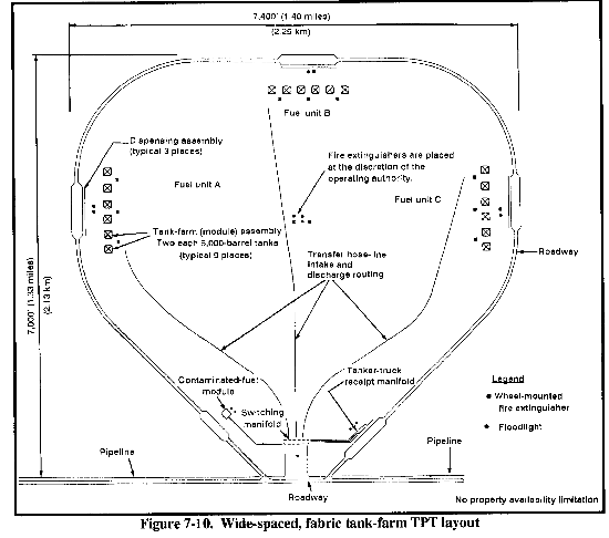
(1) Area. Figure 7-10 shows a typical wide-spaced TPT layout. It has been arranged to make full use of the transfer hose lines between fuel modules. The layout assumes that adequately sized property is available. The equipment is wide-spaced for security reasons. Terrain or operational situations could account for different appearances in wide-space layouts. The installing and operating authority makes the final determination of TPT layout. In a relatively secure area or when property availability is limited, the layout arrangement should be a close-spaced TPT layout (Figure 7-11).
(2) Access. Road access should always be considered when planning a TPT site. However, the site should have a limited number of entry points. Each entry point should have a control or checkpoint to monitor and route traffic in and out of the area. A road capable of supporting two-way tanker-truck traffic should run along the perimeter of the TPT site, giving access to each fuel unit's fuel-dispensing assembly. In the fuel-dispensing assembly areas, the roadway should be at least 40 feet wide. Through traffic should be routed away from the fuel-dispensing area. Fuel-handling areas are necessary for the contaminated-fuel module and the tanker-truck receipt manifolds.
Although not shown on the layout, secondary roadways should be in the TPT to allow for movement of material-handling equipment, pumps, and fire-suppression equipment and for maintenance access. Culverts must be constructed where hose lines intersect roadways to facilitate vehicle movement. Access must be provided to the pumps and near each tank berm.
(3) Fire-Suppression Equipment. A wheel-mounted fire extinguisher should be located near each tank berm, fuel-dispensing assembly, and tanker-truck receipt assembly and at the contaminated-fuel module. Extra units should be at a central point ready for use anywhere in the TPT. Covered shelters or containers for housing the kevlar fire-fighting clothing and extra fire-fighting supplies should be at central, easily accessible locations around the TPT. A 20-pound, hand-held fire extinguisher should beat each pump, floodlight set, and fuel-dispensing area and at other operating areas, as determined by the operating supervisor. Personnel must know where all of the fire-fighting equipment is at all times to prevent confusion in an emergency. Visible signs indicating the locations of fire extinguishers would be appropriate.
(4) Floodlight Sets. These sets should be in the fuel-dispensing areas, fuel-receipt areas, and heavy operating areas around the pumps and the switching manifold.
b. Tank-Farm-Assembly (Module) Layouts. Due to different site conditions and operational requirements, one layout design for the tank-farm modules in a TPT is not possible. The installation group modifies the layout, as necessary. Use these layouts as guidelines towards establishing an actual layout for most field situations.
(1) Area. The location of the 210,000-gallon tanks and their berms is the controlling factor in selecting a TPT site and layout. The recommended spacing between the tanks is at least 50 feet. Setting these tank locations defines the rest of the layout. Variations will occur due to uneven terrain, obstacles to be bypassed, and differences in hose sections caused by specification length tolerances. The following lists recommended spacing for tanks and berms:
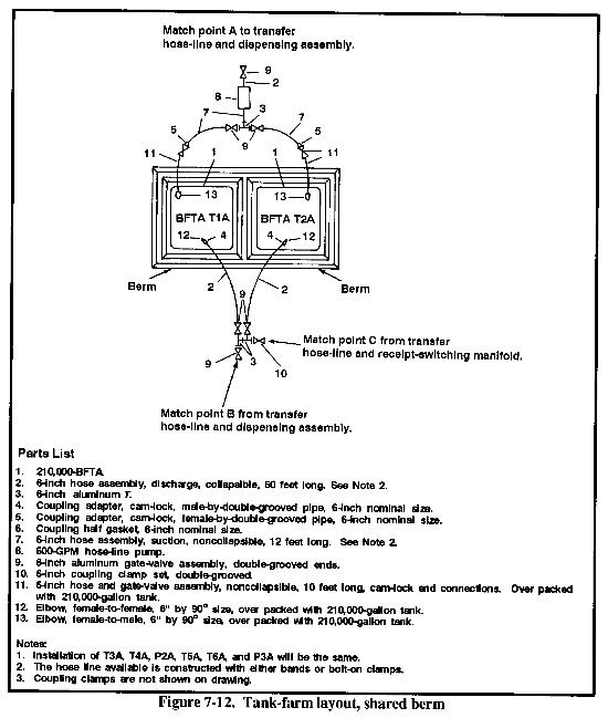
- Pairs of tanks with a common berm wall need a cleared, level area about 215 feet square for each pair. When using sandbags to construct the berm, the area requirement is about 190 by 100 feet.
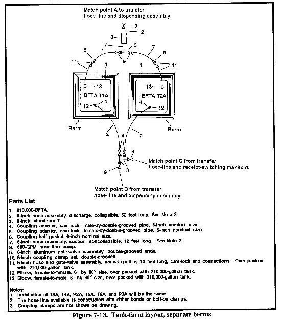
- Tanks with individual berms need an area for the tank and berm about 115 feet square. When using sandbags, the area requirement is about 100 feet square.
Figure 7-12 shows a layout that has limited space or a shortage of berm material; pairs of 210,000-gallon tanks share a berm. Figure 7-13 shows a layout that has sufficient space and berm material; each 210,000-gallon tank has its own berm. If layout changes are made, valve locations must remain unchanged from those shown on the typical layouts. If the relationships between valves are changed, the operating instructions must be changed accordingly, and all operating personnel notified.
(2) Elevation. Tank elevation relative to the rest of the TPT is important in tank location. To allow for high vapor-pressure fuels, try to keep the tank bottom and suction pump pad at the same level to maximize the suction head available to the pump. If you have to install a TPT on sloping terrain, install the tanks on the lower side of the slope to avoid flooding the pump-operating area in case a tank and berm break. Doing so accounts for the safety factor. The pump pad should not be more than two feet higher than the tank pad or it may be difficult to pump the tank dry when required.
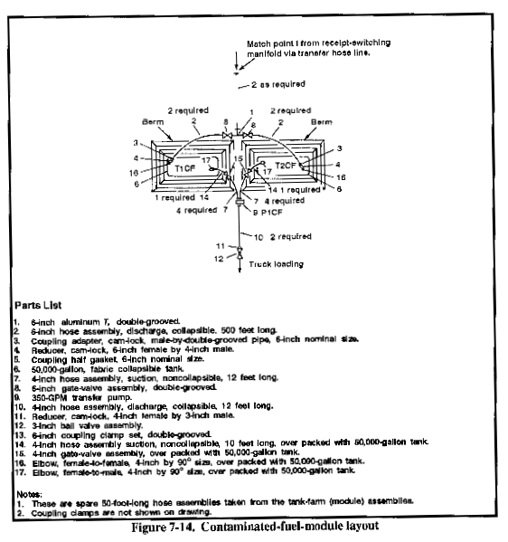
c. Contaminated-Fuel-Module Layout. Place this layout (Figure 7-14) between the associated pipeline and the switching manifold.
(1) Area. Two 50,000-gallon, collapsible fabric tanks with separate berms will each require a level area of about 60 by 100 feet (46 by 87 feet when using sandbags). If the tanks share a berm, the area should be about 105 by 100 feet (96 by 87 feet when using sandbags). Allow space for the 350-GPM transfer pump used with the contaminated-fuel module.
(2) Access. There must be road access to the contaminated-fuel module so tanker trucks can load from the 50,000-gallon tanks, as required. The graded area should be about 40 by 100 feet.
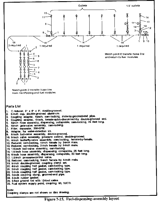
d. Fuel-Dispensing-Assembly Layout. This layout (Figure 7-15) is about 525 feet long. A 50-by 600-foot (minimum) section should be graded for the assembly. A graded area about 120 by 700 feet for traffic and parking while loading should be next to the assembly area.
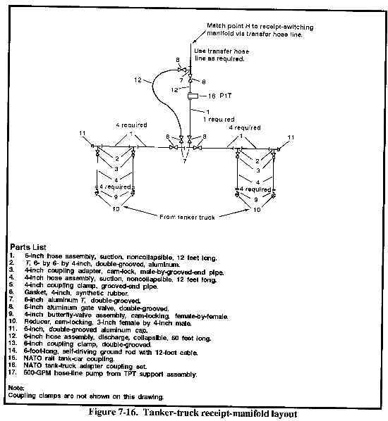
e. Tanker-Truck Receipt-Manifold Layout. This layout (Figure 7-16) may be off to one side of the switching manifold or next to the fuel-dispensing assembly. A 6-inch hose line from the transfer hose-line assembly connects the tanker-truck receipt manifold to the switching manifold. Using a hose line gives flexibility to locating the receipt manifold.
(1) Area. The recommended graded area is about 120 by 700 feet.
(2) Road Access. Road access is important because heavy truck traffic will occur in this area of the TPT.
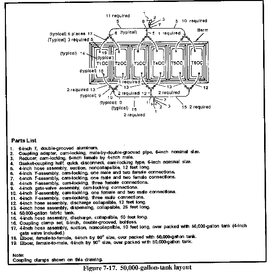
f. Optional Configuration Layout. Included in this layout are 50,000-gallon, fabric, collapsible tanks (maximum of six) and the valves, hoses, and fittings to connect them. Use the tanks to replace or supplement the 210,000-gallon tanks or place them in a separate area. Figure 7-17 shows a layout using six tanks. Each pair of tanks requires a level area about 105 by 100 feet (96 by 87 feet when using sandbags). If the site has less than six tanks, modify the layout.
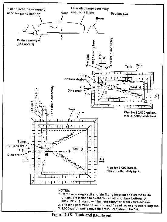
g. Typical Pad and Berm Design. All tanks are installed on pads inside berms to contain spills and isolate fires that result from spills. Figure 7-18 shows a basic design for tank berms and pads.
(1) Site Selection. Carefully select the sites for the tanks and their berms. You should consider space, terrain, soil consistency, and accessibility. Once you select the site, clear and grade it so that the final tank pad will have about a 10-degree slope toward the drain assembly closest to the tank's pump-suction fitting. This will minimize the amount of fuel remaining after full pump down. Remove all sharp objects, rocks, sticks, and so forth that might puncture the fabric tanks.
(2) Construction Materials.
(a) Earth. Berms are normally constructed of earth from the surrounding area. The more impermeable the soil, the better. A high clay content is best to avoid leaks and keep the berm in shape. Some rock and gravel content is okay, since it will tend to avoid washout.
(b) Sandbags. You can use sandbags to construct berms if site conditions preclude earth construction. However, sandbag berms will not hold a tank spill very well unless you seal the gaps between bag ends. Heavy clay packing between joints will help, but considerable leakage can take place. Sandbags are supplied with the TPT.
(3) Liners.
(a) Low-density polyethylene. Tank pads and berms may be lined with a heavy gauge plastic sheeting if soil permeability is a problem at the site. Construction-grade, low-density polyethylene, preferably with a fiber net molded in, is acceptable. Take care to adequately overlap and, if possible, seal the joints. Low-density polyethylene can be heat-sealed at the joints if time and site conditions permit before the fuel arrives.
Another sealing method is to tape the joint with 2- to 4-inch, self-adhering plastic tape. A light earth or sand fill over the liner, particularly over the tank pad, is recommended. If you use a drain line that penetrates the berm, pierce a section of the liner and tie it tightly with synthetic cord around the drain pipe to avoid a washout or leak. You can also use plastic self-adhering tape that overlaps the liner and the drain pipe. Sealing tape and plastic sheeting are not supplied with the TPT.
(b) Prefabricated polyethylene. In certain environmental situations, you may procure a prefabricated, polyethylene berm liner, as authorized by the government. These liners are--
- Size 4,50,000-gallon.
- Size 5,210,000-gallon.
(4) 210,000-Gallon Tank. The dimensions of the tank and the minimum berm size are--
- Empty tank: 68 feet 6 inches by 68 feet by 6 inches.
- Filled tank: 66 feet by 66 feet by 6 feet 8 inches.
- From toe of berm to tank wall when filled: 4 feet.
- Berm height, to contain full tank with 1-foot freeboard: 5 feet 6 inches.
(5) 50,000-Gallon Tank. The dimensions of the tank and the minimum berm size are--
- Empty tank: 26 by 66 feet.
- Filled tank: 24 feet by 64 feet by 5 feet 8 inches.
- From toe of berm to tank wall when filled: 3 feet.
- Berm height, to contain full tank with 1-foot freeboard: 4 feet 6 inches.
(6) Berm Basin Drain. To provide a berm basin drain, install a 2-inch or larger pipe with a gate valve (used pipe and valves of any rating are acceptable) on the outside end in the bottom of the berm at the lowest end of the tank pad. The valve must be in the closed position. Open the valve only to drain water from the bermed area. If you do not install a drain, you may have to pump the basin inside the berms periodically, depending on the permeability of the soils and whether or not a sealing liner is installed. Drain pipe and valves are not supplied with the TPT.
|
NEWSLETTER
|
| Join the GlobalSecurity.org mailing list |
|
|
|


