| This chapter implements STANAG 2036. |
Chapter 7
Standard-Pattern Minefields
Emplacing standard-pattern minefields is laborious and time-consuming, but it allows better mine concealment than row mining. Standard-pattern laying is well suited for protective and nuisance minefields. It can be used in terrain where the nature of the ground makes row mining impracticable.
To achieve their maximum effect, mines must be laid so that they cannot be seen and so that a vehicle's wheel or track or a person's foot exerts enough pressure to detonate them.
The method used to lay mines depends on the mine operation, the type of ground in which the mine is to be laid, and the type of ground cover that is available for camouflage.
COMPONENTS
MINE STRIPS
The mine strip is the foundation of a standard-pattern minefield. If a mine strip was laid in one straight line, the enemy could easily locate the mines; therefore, mine strips are laid in several segments as shown in Figure 7-1.
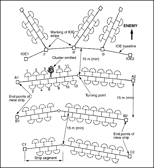
Figure 7-1. Minefield layout
When siting, laying, and recording mine strips, all measurements are expressed in meters. Directions are recorded as magnetic azimuths, in degrees.
MINE CLUSTERS
The cluster is the basic unit of a minefield. It consists of one to five mines that are laid within a 2-meter-radius semicircle (Figure 7-2). When clusters are placed in a mine strip, they are numbered progressively and may consist of--
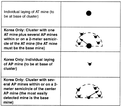
Figure 7-2. Cluster compositions
Clusters are placed at 6-meter intervals, center to center, to form rows. Two parallel rows, 6 meters apart, form a mine strip. The arrangement of clusters in a mine strip is shown in Figure 7-3.
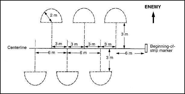
Figure 7-3. Arrangement of clusters in a mine strip
RULES FOR POSITIONING CLUSTERS WITHIN A STRIP
The first cluster is placed on the enemy side of the strip centerline, 6 meters from the beginning-of-strip marker. The following clusters are numbered consecutively. Odd-numbered clusters are always on the enemy side of the strip centerline. The direction of laying follows the numbering (A1 to A2, B1 to B2, and so on).
The IOE is normally the first part of the minefield encountered by the enemy. It consists of a baseline from which short strips are extended (Figure 7-4). Short strips along the IOE deceive the enemy on the minefield's pattern, spacing, and size. IOE placement and composition are largely dictated by the time allowed for laying the minefield, terrain conditions at the laying site, and the tactical situation.
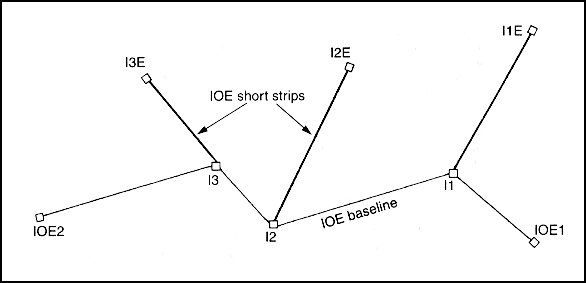
Figure 7-4. IOE baseline with short strips
The IOE baseline extends from one end point (IOE1) to another end point (IOE2). The laying direction is indicated by end-of-strip markers. Laying always begins at IOE1. Intermediate or turning points are marked in consecutive order beginning with I1. On the enemy side of the IOE baseline, short strips are extended from turning points at irregular angles. They are identified by turning-point markers.
Turning points should be no more than 45 degrees from the last azimuth. The length of short strips is not standard. A marker is emplaced at the end of each short strip. Markers are numbered in consecutive order beginning with I1E for recording purposes. No trip wires are used in the IOE, but AHDs may be employed.
Korea Only: AP mines actuated by trip wires are placed on the enemy side of each regular strip. No more than one mine per cluster uses trip wires, and no more than two trip wires extend from the mine. Trip wires are angled toward the enemy and should be at least 2 meters from the cluster, the lane border, and the minefield boundary. Trip wires are only used with AP fragmentation mines; they are not considered to be AHDs.
STANDARD-PATTERN MINEFIELD RULES
The following rules apply to tactical and protective standard-pattern minefields. They do not apply to nuisance minefields.
Clusters
- A cluster is a 2-meter-radius semicircle located 3 meters off the strip centerline.
- There are two types of clusters--live and omitted.
- Clusters are omitted within lanes and gaps; in areas less than 2 meters from boundaries, lanes, or another cluster (including the IOE); and in areas where the terrain (trees, rocks) prohibits emplacement.
- The base mine in a live cluster is the first mine laid. It is 3 meters from the strip centerline.
- When a live cluster contains an AT mine, the mine is always used as the base mine. (Korea Only: If an AT mine is not present, the largest metallic AP mine is the base mine.)
- The first cluster in a mine strip is located on the enemy side, 6 meters from the beginning-of-strip marker.
- The minimum distance between a cluster and a lane, a gap, a boundary, or another cluster is 2 meters (measured from the edge of the cluster).
- Cluster composition is the number of mines, by type, in any cluster in a specific group.
- Cluster composition remains the same through the entire mine strip and is recorded on DA Form 1355.
- Korea Only: The types of AP mines may vary within a cluster.
- The cluster boundary must at least 15 meters from the minefield perimeter fence.
- Clusters are numbered, beginning with the first cluster on the enemy side. Odd-numbered clusters are always on the enemy side of the strip, and even-numbered clusters are always on the friendly side.
- A live cluster contains one AT mine. (Korea Only: A live cluster contains as many as five mines, only one can be an AT mine).
- Omitted clusters do not contain mines, but they are numbered and recorded on DA Form 1355 (see Chapter 8).
Regular Strips
- A regular strip (sometimes referred to as a lettered strip) consists of a strip centerline and two rows of clusters (Row 1, enemy side; Row 2, friendly side).
- Regular strips are marked and recorded. They are designated by letters (A, B, and so forth), with Strip A being closest to the enemy.
- A standard-pattern minefield contains at least three regular strips.
- The minimum distance between strip centerlines is 15 meters; there is no maximum distance.
- Safety tapes are used to ensure that personnel installing trip wires do not move forward into armed clusters. A safety tape is used behind each regular strip. Safety tapes are 8 meters from the strip centerline (3 meters from the outer edge of the cluster).
- The marking of end points indicates the direction of laying (for example, A1 to A2).
IOE
- The IOE consists of a baseline from which short strips are extended.
- The IOE is located on the enemy side of the minefield.
- The number of clusters in an IOE is approximately one-third the number used in a regular strip.
- The first cluster along a short strip is placed on the enemy side and must be at least 6 meters from the IOE baseline; the cluster boundary must be at least 2 meters from the IOE baseline (Figure 7-5). If the short strip is exactly parallel to the enemy direction of travel, the NCOIC designates the enemy side of the strip.
- The IOE baseline is labeled at the beginning (IOE1) and end (IOE2) according to the direction mines are emplaced.
- Short strips are labeled at turning points (I1) and at the end (I1E).
- The IOE contains a safety tape that is 2 meters behind the IOE baseline and runs parallel with it.
- The IOE baseline is at least 15 meters from any point of the strip centerline of a regular strip; there is no maximum distance.
- An IOE short strip is at least 15 meters from another IOE short strip; there is no maximum distance.
- AHDs may be employed.
IOE Short Strips
- Short strips originate from turning points along the IOE baseline.
- The number and length of short strips depend on the tactical situation and the resources available.
Trip Wires (Korea Only)
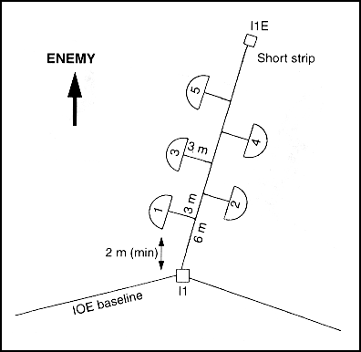
Figure 7-5. Clusters on an IOE short strip
- Trip wires are not used in an IOE.
- Trip wires may be used in regular strips, but only one mine per cluster may be actuated by a trip wire.
- Trip wires are employed no closer than every third cluster.
- No more than two trip wires can be used on one mine.
- Trip wires are used only on the enemy side of the strip.
- Trip wires are not considered AHDs.
- Trip wires are located at least 2 meters from a lane, a safety tape, a cluster, another trip wire, the IOE baseline, and the minefield perimeter fence.
- Trip wires can only be used with AP fragmentation mines.
Turning Points
- Clusters must be at least 3 meters from turning points.
- The first cluster after a turning point is laid on the opposite side of the strip centerline from the last cluster before the turning point.
- The angle of any given turning point cannot exceed 45 degrees from the last azimuth. (This ensures a minimum distance of 2 meters between cluster boundaries in the same row.)
Lanes
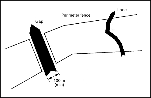
Figure 7-6. Minefield lanes and gaps
- Lanes are sited before laying begins.
- Lane locations should not be obvious.
- Clusters are not laid within 2 meters of lane edges.
- Lanes are zigzagged, not straight.
- Lanes cross the strip centerline at approximately right angles.
- Direction changes will not exceed 45 degrees. (This ensures that long vehicles will be able to negotiate turns.)
- The number of lanes must be sufficient to ensure that no one lane is overused and turned into an obvious track.
- Sufficient mines are stockpiled so that the responsible unit can close lanes suspected of being located by the enemy.
- Recommended minefield lane widths are--
- Footpath: 1 meter.
- One-way vehicle lane: 8 meters.
- Two-way vehicle lane: 16 meters.
Gaps
- Minefield gaps (Figure 7-6) are left so that friendly forces can pass through the minefield in tactical formation.
- Gaps must be at least 100 meters wide.
- Gaps are sited before laying begins.
- Gaps are located along recognizable features (fences, tracks, creeks).
- Gaps should run straight through a minefield and not contain bends.
- Sufficient mines must be stockpiled so that the responsible unit can close gaps when necessary.
- Gaps should closely resemble the rest of the minefield so that they will not be discovered by the enemy.
- The ground within a gap should be disturbed with tracks to represent the passage of a mine-carrying vehicle.
- Signs of mine laying (digging, scattered spoil, crates) should be visible in a gap.
General
- The farthest extremities of a regular strip determine the minefield front.
- Minefield depth is measured from the first to the last strip and includes the IOE (if applicable).
- Strips can be laid left to right or right to left.
- Back azimuths are not used to record the minefield.
- The minefield will have two landmarks located to the rear, never to the extreme side or front.
- GPSs can be used to determine the coordinates for minefield landmarks and reference points.
Do not use GPSs to chart or record minefield perimeter coordinates or to determine safe routes through or around existing minefields. |
- If landmarks are more than 200 meters away from the last regular strip or are out of the direct line of sight, intermediate markers are placed at least 75 meters from the last end-of-strip marker.
- Landmarks can be used for more than one minefield. They are recorded on DA Form 1355.
LOGISTICAL CALCULATIONS
Emplacing standard-pattern minefields allows the unit to calculate the number of mines required for a minefield accurately.
To simplify the calculation process, a minefield requirements computation work sheet (Figure 6-1) has been developed. Step-by-step procedures for completing the work sheet are shown in Figure 6-2.
CLUSTER CALCULATION
Accuracy is essential when emplacing a standard-pattern minefield. The following check system has been designed so that the minefield OIC can accurately record the number of mines laid. Compare the strip feeder report with the--
EXAMPLE: You receive a strip feeder report for Strip A. There are 26 clusters in the strip. The strip has three segments (30, 42, and 21 meters) and two turning points.
Step 1. Add the total length of the strip as determined by the recording party.
Step 2. The first and last cluster in the strip are located 6 meters in from the end-of-strip markers. Subtract 12 from Step 1.
Step 3. Clusters are not located on turning points. Multiply the number of turning points by 3 and subtract it from Step 2.
Step 4. Divide Step 3 by the cluster spacing.
Step 5. Add one cluster, because when a line is divided, there is one more interval than spacing.
From these computations, the minefield OIC is able to cross-check the information on the strip feeder report. In this example, Strip A should have a total of 26 clusters, less any omitted clusters.
PLATOON ORGANIZATION
The platoon is the basic unit used to install a standard-pattern minefield. Orders to the laying unit OIC specify the proposed location, the length, and the mine type and density. The platoon organization and equipment are shown in Table 7-1.
The OIC performs a map study, and if the situation permits, conducts a ground reconnaissance of the site. He determines locations for mine strips, landmarks, fences, mine dumps, and approaches. Using the minefield requirements computation work sheet (Figure 6-1), the OIC determines the required number of mines and other materials. He arranges for mines to be delivered and organizes the platoon into siting, laying, recording, marking, and mine-dump parties.
Siting Party
The siting party places boundary stakes or pickets as strip markers at the beginning and end of each mine strip and at the points where strips change direction. It lays tape on the centerlines of each strip, lane, and traffic path. After siting is complete, the siting party augments other parties.
Laying Parties
One laying party is responsible for installing, arming, and camouflaging all the mines on a strip or a portion of a strip. Each laying party is then assigned additional strips.
Recording Party
The recording party obtains the necessary reference data, prepares DA Form 1355 (see Chapter 8), and when needed, installs intermediate markers.
Marking Party
The marking party erects fences and signs to mark minefield boundaries and lanes. After marking is complete, the marking party augments other parties.
Mine-Dump Party
The mine-dump party, controlled by the PSG, is composed of personnel who are not working as members of other teams. It accounts for all Class IV and V supplies that arrive from other sources, organizes mine sets at the mine dump, and hauls additional supplies as required. The PSG is not required to stay at the mine dump continuously; he has the flexibility to move around the area to perform other activities.
MINE-EMPLACEMENT PROCEDURES
Mine-emplacement procedures are shown in Figure 7-7. In the illustration, the minefield is laid from right to left.

Figure 7-7. Minefield-emplacement procedures
The OIC arrives at the site with the siting and marking parties. He goes to the right or left (depending on the laying direction) rear boundary of the minefield. This part of the minefield is the farthest from the enemy. The OIC indicates the starting point of the rear strip (this is Strip C in a three-strip minefield), and the siting party emplaces a beginning-of-strip marker.
The OIC designates a starting point for the marking party that is at least 15 meters to the right of the boundary stake. He indicates where the minefield marking fence should be placed. The marking party immediately begins to install fence pickets, working in a counterclockwise direction.
When all the pickets are installed, the marking party encircles the field with a single strand of barbwire (at waist height) and emplaces mine signs. Personnel emplace a second strand of barbwire if required.
From the boundary stake of Strip C, the OIC moves in the direction of the enemy and establishes the starting point of Strip B. Strip centerlines should not be parallel nor less than 15 meters apart. Two members of the siting party emplace a beginning-of-strip marker at the starting point of Strip B. The remaining two members lay tape between the two strips and fasten the tape to the ground at frequent intervals to prevent movement. This procedure is followed until the beginning-of-strip markers of the three regular strips (C, B, and A) and the IOE on the right-hand side of the minefield have been installed.
At the IOE beginning-of-strip marker (IOE1), the OIC gives the siting party a sketch of the minefield and instructions on siting the IOE baseline and strip centerlines. The NCOIC and one other member of the siting party immediately begin setting stakes to indicate the IOE baseline. The centerline laying team lays tape on the IOE baseline, leaving tape reels where tapes run out. Short strips extending from the IOE baseline are established at the same time. Each short strip starts with a marker that is designated as I1, I2, and so forth and ends with a marker that is designated as I1E, I2E, and so forth. Turning points are not used on short strips.
Upon reaching the IOE end-of-strip marker (IOE2), the NCO moves away from the enemy side, establishes the left boundary stake of Strip A, stakes out Strip A, and repeats the procedure until all strip centerlines are taped. All stakes are driven flush with the ground.
While the IOE is being taped, the recording party obtains reference data for the DA Form 1355. Working behind the siting party, the recording party starts from Landmark 1 (designated by the OIC) and proceeds to C1. After C2 has been sited, the recording party proceeds from Landmark 2 to C2 to establish the distance and the azimuth. Finally, the recording party ties C1 and C2 to both landmarks in case one of the landmarks is removed or destroyed. The amount of detail obtained by the recording party depends on the tactical classification of the minefield and any special orders. Aerial photographs taken of the minefield before the tracing tape is removed become valuable supplements to the DA Form 1355.
As soon as laying parties arrive at the site with mines, they establish mine dumps a minimum of 150 meters apart and 50 meters behind the field. They uncrate and stack AT mines and place fuses and detonators in separate boxes. Fuse types are not mixed. (Korea Only: AP mines are left in their crates, and the crate lids are removed.)
When the siting party completes the centerline staking, it installs lane tapes and traffic tapes, respectively. Lane tapes are used by tactical vehicles and patrols. Traffic tapes are used by laying personnel to assist in camouflage and to reduce the amount of traffic on strip centerlines. Traffic tapes are laid perpendicular to the minefield trace at 100-meter intervals.
MINE EMPLACEMENT
The laying party must know the cluster composition of the strip, the location of any omitted cluster, and future lane locations. When the centerline tape for a regular strip has been installed, the NCOIC designates all but two members of the laying party to emplace mines in the ground. The remaining two soldiers, usually the most experienced, are designated as fusers and are responsible for arming mines. Layers carry the maximum load of mines to be used as base mines in the clusters. Fusers carry the fuses and the detonators.
The NCOIC moves to the right or left (depending on the laying direction) beginning-of-strip marker of the strip and organizes the layers into one column to his rear, directly on the centerline. He measures 6 meters along the centerline for the first cluster and, pointing perpendicular from the centerline and in the direction of the enemy, indicates the placement of the base mine. The first layer on the enemy side places a mine on the ground, 3 meters from the centerline.
The NCO measures 3 more meters and indicates the placement of the second base mine on the opposite (friendly) side of the strip. The first layer on that side places a base mine on the ground. As the initial load of mines is laid, each layer returns to the nearest mine dump for another load. Fusers follow behind layers and insert mine fuses, but they do not arm the mines. This procedure is followed until the end-of-strip marker on the far side of the minefield is reached.
Korea Only: The NCO tells layers the number and type of mines to be placed next to the base mine in each cluster. As AP mines are being placed, the NCO proceeds along the strip and ensures that the proper number of AP mines is placed in each cluster. The NCO places a spool of trip wire next to the mines that are to be activated by trip wire.
When all the mines are positioned in clusters, one layer is assigned to dig the holes for all the mines in a cluster. He places the spoil from the holes in sandbags and leaves the sandbags beside the base mine in each cluster. The layer checks the positioning of the mines in the holes, removes the mines from the holes, and places the mines beside the holes. (Korea Only: The layers anchor trip wires with nails or stakes and wrap the loose ends of trip wires around the fuses.)
When digging has progressed at least 25 meters from the first mine laid, the arming procedure begins. Fusers arm all the mines in a cluster, beginning with the mine farthest from the centerline and work backward. They place all the mines in the holes (Korea Only: attach trip wires) and arm and camouflage the mines. They place filled sandbags on the centerline of the strip, opposite the base mine. Fusers keep their back toward the centerline. Other personnel must remain at least 25 meters from the fusers (Figure 7-8)
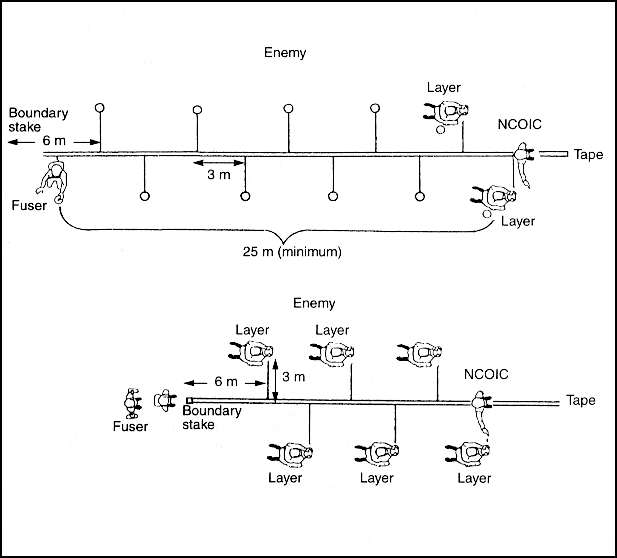
Figure 7-8. Laying and fusing mines
Mines located in lanes are not initially buried. They are placed aside to prevent confusion when counting clusters. The mines can be buried after the lane is closed. Upon completing the arming operation, fusers give the safety clips to the NCO, who verifies that all the mines have been armed and camouflaged. The NCO checks the strip and ensures that sandbags, tape, and debris have been picked up. The NCO gives the safety clips to the PSG, who buries them 30 centimeters to the rear of the beginning-of-strip marker.
All mines and other explosive items are recorded upon issue. They are summarized on a mines tally sheet (see Table 7-2). If more than one mine dump is established, a mines tally sheet is kept at each dump and the information is later transferred to a master tally sheet.
The PSG ensures that the number of mines used per tally sheet is entered on the DA Form 1355.
When a lane is no longer required through a minefield, it is closed by a l ane-closure team that consists of one NCO and two other soldiers. Before closure starts, the NCO checks the minefield record to ascertain the--
- Width of the lane.
- Cluster composition of each strip.
- Total number of mines required.
- Number of strips that intersect the lane.
- Azimuth of each strip.
- Distance between strips, along the lane centerline.
- Location of the mine dump.
The procedures for lane closure is as follows (see Figure 7-9):
- The lane-closure team moves along the safe-lane centerline until it arrives at the strip safe-lane marking picket.
- The NCO lays out a strip centerline tape and a tape along both sides of the safe lane to mark its boundaries.
- The team lays clusters.
- The team recovers the tapes.
- The above steps are repeated at successive strips.
- The NCO amends the DA Form 1355.
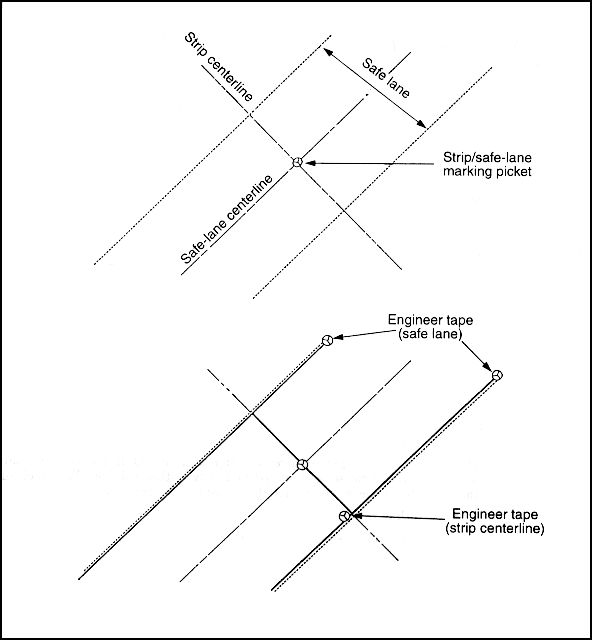
Figure 7-9. Lane closure
NOTE: When gaps must be closed, fences are temporarily erected along the side boundaries. They are removed later to avoid the indication of a passage through the minefield.
NCOICs do not act as working members of their parties; they ensure that--
- No one moves back into a mined area.
- Any irregularity, such as an omitted cluster, is recorded.
- All safety devices are recovered and checked against the minefield record.
Safety tapes are used to create a network of safe routes through a minefield. They may be removed progressively but are normally left in place until the minefield is complete.
Korea Only: When trip wires are used, safety tapes are laid between strips where the trip wire will be positioned (including Strip A and the IOE baseline). If trip wires are not used, safety tapes are recommended but are not mandatory.
NUISANCE MINEFIELDS
SITING
Consider the following factors when siting a nuisance minefield:
- The effort needed by the enemy to bypass a mined area.
- The importance of an area or a route to the enemy.
- Achievement of the goal (use the minimum amount of effort needed to maximize casualties and the effect on enemy morale).
Remember, the more ingenuous the methods of concealment, the longer it will take to lay mines.
Observation and covering fires are not essential and are seldom feasible for nuisance minefields. Their value depends on effective siting and concealment to cause surprise.
The minefield OIC is responsible for detailed siting and the design of a nuisance minefield. He must consider the minefield from the enemy's point of view and assess the courses open to the enemy when he encounters it. Such considerations may expose weaknesses in the initial plan and bring about a change to the proposed minefield layout or may lead to a decision to site the minefield elsewhere.
LOCATION
In wooded or hilly terrain, the enemy's logistics transport will normally be confined to existing routes. Nuisance mines at selected sites along roads can impose considerable delay on the enemy and have a cumulative effect on his resources and morale. The best sites for axial mining are--
- Natural defiles and constructed areas that are difficult to bypass (cuts, embankments, causeways, fords, forest tracks, built-up areas).
- In the vicinity of road craters, AT ditches, and any obstacles that have to be cleared.
- Around culverts.
- Demolished bridges, particularly the home bank, including likely adjacent crossing places and alternative building sites.
- Likely assembly areas.
- Covered approaches or dead space.
- In the vicinity of enemy-needed fuel, supplies, and engineering materials that cannot be destroyed or removed.
- Railroads (in or near culverts, bridges, sharp turns, tunnels, steep grades). Mines should be laid where enemy trains cannot bypass the mined area on branches or spurs.
LAYING
There is no requirement for recording the precise location of individual nuisance mines. Recording mine positions that are laid to a pattern is easy and quick. Pattern laying should be used when it can be done without prejudicing concealment.
When the number of mines to be laid on the site makes it impracticable or undesirable to lay mines in a pattern, they may be scatter-laid unless otherwise directed. Scatter-laying by hand is useful in road blocks, bridge abutments, and craters when it would be difficult and wasteful to lay mines in a pattern. Again, scatter-laying along routes to be denied to the enemy will add considerably to the delay imposed. All available types of AT mines (Korea Only: and AP mines) are used to make nuisance minefields complex and difficult to remove. Combinations of mine types should be varied constantly so that each minefield presents a clearance problem. Deeply buried mines can be included; however, they take much longer to lay. These mines may be worthwhile around craters, where the enemy is likely to need earthmoving equipment.
If a nuisance minefield is laid in a standard pattern, standard procedures are followed. If mines are selectively positioned, procedures must be tailored to suit the situation. In all occasions, however, the following rules should be observed:
- The intended position for each mine is clearly marked on the ground before laying begins.
- Laying parties work in pairs, and each pair is detailed to lay specific mines.
INSPECTION AND MAINTENANCE
Mines that are left in the ground for an extended period of time may deteriorate and malfunction for one or more of the following reasons:
- Moisture may have entered the igniter or body of the mine and either neutralized the explosive or corroded the metal parts. Such actions may be aggravated by local factors (soil acidity, wide temperature swings).
- Frost or heat may have subjected the mine to mechanical strain and caused distortion.
- Insects or vegetation may have caused obstructions.
- Animals may have turned mines over or detonated them.
Technical inspections should only be made by experienced engineers or EOD personnel. When a minefield deteriorates below the operating level, additional mine strips and/or rows must be added to restore its effectiveness. They are sited to the front or rear of the existing minefield to increase its depth. New mine strips and/or rows are treated as a separate, additional minefield.
Technical inspections of minefields are normally done at three-month intervals, and personnel work in pairs. They are done more frequently during extreme weather conditions.
HANDOVER
Minefield handover is an extremely important task. The following items need to be addressed between emplacing and overwatching units:
- Discussing minefield compositions.
- Discussing the minefield configuration and walking and/or riding the minefield trace.
- Discussing lane closure, if applicable.
- Training the unit on how to the close lane, if applicable.
- Discussing obstacle protection against enemy dismounted patrols.
- Signing over the written report (Figure 2-26).
- Discussing indirect fires.
- Reporting completion of handover to higher headquarters.
- Forwarding a copy of the written report and the DA Form 1355 to higher headquarters.
|
NEWSLETTER
|
| Join the GlobalSecurity.org mailing list |
|
|
|

