

|
RDL Homepage |
Table of Contents |
Document Information |
Download Instructions |
LESSON 2
EMPLOY SCATTERABLE MINES
OVERVIEW
LESSON DESCRIPTION:
In this lesson, you will learn the employment tactics, processes, and techniques of the Volcano, Flipper, and MOPMS. After completing this lesson, you will understand how each system is employed and how it marked and reported.
TERMINAL LEARNING OBJECTIVE:
| ACTION: | You will learn to employ scatterable mines. |
| CONDITION: | You will be given information on the employment of scatterable mines and the material contained in this lesson. |
| STANDARD: | You must demonstrate your knowledge on the employment of the Flipper, Volcano, and MOPMS. |
| REFERENCE: | The material contained in this lesson was derived from FM 20-32. |
INTRODUCTION
This lesson is presented in three parts. Part A provides basic information on the deployment tactics and techniques of the Volcano mine system. Part B provides a basis for understanding the employment of the Flipper mine dispensing system. Part C provides information on the employment of the MOPMS.
2-1. General. The Volcano multiple-delivery mine system ( Figure 2-1), can be dispensed from the air or on the ground. It can be mounted on a 5-ton vehicle, an M548 tracked cargo carrier, a HEMTT, a palletized load system (PLS) flat rack, or a UH-60A Blackhawk helicopter. The Volcano uses modified Gator mines and consists of four components ( Figure 2-2) --the M87-series mine canister, the M139 dispenser, the dispenser control unit (DCU) , and the vehicle-specific mounting hardware (aircraft also requires a jettison kit) . The Volcano uses M87 and M87A1 mine canisters. The M87 mine canister is prepackaged with five AT mines, one antipersonnel (AP) mine, and a propulsion device inside a tube housing. The M87A1 mine canister is prepackaged with six AT mines and no AP mines. The mixture of mines is fixed and cannot be altered. Mines are electrically connected with a web that functions as a lateral dispersion device as the mines exit the canister. Spring fingers mounted on each mine prevent it from coming to rest on its edge. All canisters are capable of dispensing mines with 4-hour, 48-hour, or 15-day SD times. The SD times are field-selectable before dispensing and do not require a change or modification to the base M87-series canister. The delay-arm times are 2 minutes 30 seconds for the AT mine and 4 minutes for the AP mine.
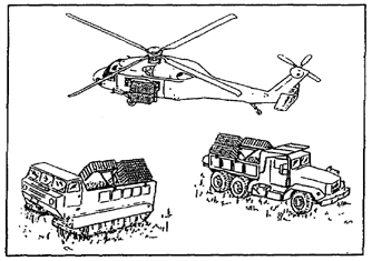
Figure 2-1. Volcano mine system
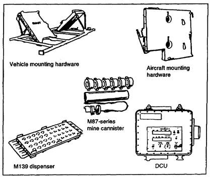
Figure 2-2. Volcano components
a. The dispenser consists of an electronic DCU and four launcher racks. Four racks can be mounted on a vehicle, and each rack can hold 40 M87-series mine canisters. The racks provide the structural strength and the mechanical support required for launch and provide the electrical interface between the mine canisters and the DCU. Mounting hardware secures the racks to the vehicle or the aircraft. Mounting hardware for the UH-60A Blackhawk includes a jettison subassembly to propel the Volcano racks and canisters away from the aircraft in the event of an emergency.
b. The operator uses the DCU to control the dispensing operation electrically from within the carrier vehicle. The DCU provides controls for the arming sequence and the delivery-speed selection and sets the mine SD times. The DCU allows the operator to start and stop mine dispensing at anytime. A counter on the DCU indicates the number of remaining canisters on each side of the carrier.
c. Mines are dispensed from their canisters by an explosive propelling charge. For ground vehicles, the mines are dispensed 25 to 60 meters from the vehicle at ground speeds of 8 to 90 kilometers per hour. The average time to emplace one ground Volcano load (160 canisters) is 10 minutes. For aircraft, the mines are dispensed 35 to 70 meters from the line of flight. The aircraft flies at a minimum altitude of 1. 5 meters, at speeds of 20 to 120 knots. This system uses the host vehicle as a power source. (Attaching the system to the vehicle does not significantly degrade its mobility. ) This system has three field-selectable SD times (4 hours, 48 hours, and 15 days) for the mines. Reload time (not including movement time to the reload site) for an experienced four-man crew is approximately 20 minutes. Except for the mounting hardware, there is total system commonality between the air and ground Volcano systems.
2-2. Employment. The primary mission of the Volcano is to provide United States (US) forces with the capability to rapidly emplace large minefields under varied conditions. The Volcano can be rapidly attached to air or ground vehicles. It is used to emplace tactical minefields; reinforce existing obstacles; close lanes, gaps, and defiles; protect flanks; and deny probable enemy air-defense sites. Volcano minefields are ideal for providing flank protection of advancing forces and for operating in concert with air and ground cavalry units on flank guard or screen missions.
a. The ground Volcano is designed to emplace large minefields in depth. It is normally employed by combat engineer units. These mounted dispensers are primarily used to emplace tactical minefields oriented on enemy forces in support of maneuver operations and friendly AT fires.
b. The system is vulnerable to direct and indirect fires, so it must be protected when close to the forward line of own troops (FLOT) . It is ideal for use as an obstacle reserve, employed when the enemy reaches a decision point that indicates future movement. Obstacles can then be emplaced in depth on the avenues the enemy is using, leaving other avenues open for friendly movement.
2-3. Emplacement. The principles and procedures of Volcano emplacement are significantly different for air- and ground-delivery systems. This lesson outlines the use of the ground-delivery Volcano system to emplace disrupt, fix, turn, and block minefields.
The principles and procedures of the air Volcano delivery system are outlined in Appendix D of FM 20-32. Both air and ground systems are capable of emplacing nonstandard minefields. However, the emplacement norms below streamline identifying resource requirements and conducting emplacement drills.
a. Air and ground Volcano systems emplace a minefield with an average AT linear density of 0. 72 mine per meter and an AP linear density of 0. 14 mine per meter. These densities may vary slightly since some mines will fail the arming sequence and self-destruct 2 to 4 minutes after dispensing. Additionally, some mines may not orient correctly, will not deliver their full mine effect, and will not produce a K-Kill. The probability of failing the arming sequence and misorienting is relatively small and does not appreciably degrade the minefield's lethality. For tracked vehicles, the AT density yields more than 80 percent probability of encounter. Volcano AT mines do not have antihandling devices but are highly sensitive to any movement once they are armed. Any attempt to remove the mines will likely result in detonation.
b. The basic site layout is extremely important, and it is the same for air and ground Volcano minefields. The limits of air and ground Volcano minefields are marked before emplacement when the situation allows it. The minefield is not premarked when the situation (offensive operations or situational obstacles) does not allow it. If the mines have not self-destructed, the minefield is marked before the unit leaves the area or turns it over to an adjacent unit. The NCOIC of the minefield emplacement ensures that the following is completed:
(2) The start and end points of the strip centerline are marked based on minefield front and the number of strips. For a ground Volcano minefield, guide markers are emplaced along the path of the centerline but are offset left to allow the host vehicle to remain on the centerline.
(3) Minefield marking must leave a gap on each centerline for vehicle entrance and exit when using a ground-delivery system. The number of guide markers depends on the terrain and visibility. Guide markers are not required for an air Volcano minefield because the pilot will use the start and end points of the centerline as reference points.
c. Figure 2-3 illustrates the emplacement pattern for standard disrupt and fix minefields using the ground or air Volcano. Disrupt and fix minefields use only one centerline to give a minefield depth of 120 meters (ground) or 140 meters (air) , not including the safety zone. The strip centerline is 277 meters (ground) or 278 meters (air) long. The minefield is emplaced as follows:
(1) The host vehicle moves toward the start point, achieving and maintaining the ground or air speed selected on the DCU.
(2) The operator depresses the launch switch on the DCU as the vehicle passes the start marker, and he stops dispensing mines when the vehicle passes the end marker.
(3) The operator dispenses 40 canisters (20 on each side) along the centerline.
(4) The vehicle moves out of the minefield (for ground emplacement), marks the exit, and waits a minimum of 4 minutes before approaching the minefield. This delay allows faulty mines to self-destruct.
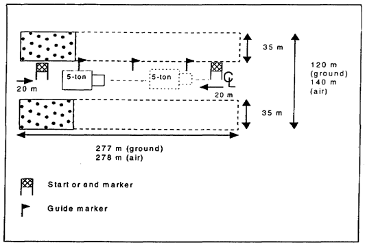
Figure 2-3. Volcano disrupt and fix minefields
d. Turn and block minefields (Figure 2-4) are emplaced using the same basic procedures as those used for disrupt and fix minefields. However, turn and block minefields use two strip centerlines along a front of 555 meters (ground) and 557 meters (air) . During site layout, centerlines are separated by at least 320 meters for both ground and air delivery. This gives a total minefield depth of 440 meters (ground) or 460 meters (air) . The minefield is emplaced as follows:
(1) The host vehicle moves toward the start point, achieving and maintaining the ground or air speed selected on the DCU.
(2) The operator depresses the launch switch on the DCU as the vehicle passes the start marker, and he stops dispensing mines when the vehicle passes the end marker.
(3) The operator dispenses 80 canisters along each centerline (40 on each side) ; therefore, turn and block minefields require a total Volcano load of 160 canisters. Wherever possible, two ground Volcanoes are employed simultaneously on turn and block minefields.
(4) The vehicle moves out of the minefield (ground emplacement) , marks the exit, and waits a minimum of 4 minutes after dispensing the first strip before dispensing the second strip. This allows mines that fail the arming sequence to self-destruct.
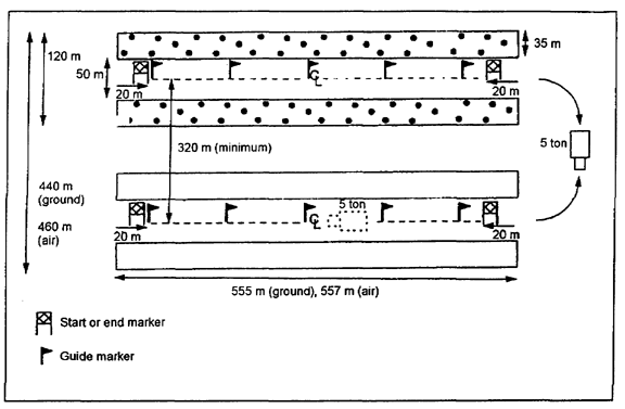
Figure 2-4. Volcano turn and block minefields
2-4. Recording. When the Volcano minefield is completed, the OIC identifies an NCO to be the recorder. The NCO collects data from the NCOICs of the emplacing squads and completes a scatterable minefield report as outlined in Chapter 8 of FM 20-32. Figure 2-5 shows the format for completing the scatterable minefield report. The OIC ensures that the report is completed on time and is accurate.
2-5. General. The M38 Flipper is a manual mine dispenser that is designed to emplace M74 AP and M75 AT mines (Figure 2-6) . It is a simple dispensing system and uses little automation to load and dispense mines. In short, mines are loaded by hand into a feeder chute. The operator determines the pattern by manually pivoting the dispenser across a 180-degree arc. Mines are dispensed in a 35-meter arc from the host vehicle. The Flipper provides the commander with great flexibility since it can be mounted on M113 armored personnel carriers, M548 cargo carriers, 2 1/2-ton cargo and dump trucks, and 5-ton cargo and dump trucks with no modification. The Flipper weighs approximately 58. 5 kilograms, and it uses the electrical power system of the host vehicle. It can dispense six mines per minute, and deployment requires only two people-the mine loader and the vehicle operator.
Figure 2-5. Scatterable minefield/munition field report and record work sheet
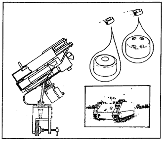
Figure 2-6. Flipper mine dispenser
2-6. Employment. The Flipper has two disadvantages—the emplacement method requires the crew to be exposed during operation, and it is difficult for soldiers to dispense mines on the move. However, when mounted on a tracked vehicle, the Flipper's mine-dispensing capability can keep up with maneuver forces during movement; and the Flipper can emplace a minefield quickly in response to a threat. An additional advantage is the system's versatility when emplacing mines. It can be used to emplace standard tactical minefields, small point minefields, or protective minefields relatively close to friendly positions. Flipper minefields can be used to reinforce existing obstacles and reseed gaps and lanes in minefields. Manually aiming the dispenser allows engineers to emplace scatterable mines with great accuracy on a point target or in restrictive terrain.
a. The NCOIC ensures that all personnel are cautioned about operating the Flipper in a hazardous area. If a mining mission requires the dispensing of mines over hilly terrain, mining should be accomplished while traversing across the top of the hill or going uphill. Mining missions should not be accomplished when descending a hill, because the mines may roll to the base of the hill.
b. The operator can vary Flipper minefield density by adjusting the number of mines dispensed at each stopping point. Minefield composition is determined by the number of AT and AP mines the operator dispenses at a given stopping point.
c. When emplacing a standard minefield (disrupt, fix, turn, or block) with the Flipper, the crew uses a set stop-and-dispense procedure. During site layout, dispensing markers are placed every 35 meters along a centerline. These markers are offset from the centerline, half the width of the vehicle to the left (relative to the direction of emplacement). This allows the vehicle driver to guide on the markers during movement and allows the vehicle to remain on the centerline.
d. The minefield should be emplaced as follows:
(1) The host vehicle moves toward the start point and stops the vehicle when he reaches a dispensing marker.
(2) The driver then traverses the dispenser to the zero-degree position (at a right angle to the direction of emplacement, toward the enemy) as shown in Figure 2-7. This is the Number 1 mine position.
(3) The operator dispenses mines in the order shown, traversing the dispenser in a 180-degree arc from the enemy side to the friendly side. The target angles shown are a guide that can be used to achieve the optimal spacing between mines and to achieve uniform linear density. All angles arc relative to the Number 1 mine at zero degrees.
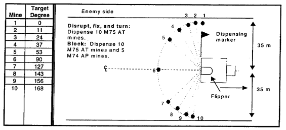
Figure 2-7. Flipper stop-and-dispense point
(4) Crews may want to fabricate an aiming circle and mount it to the Flipper to make dispensing more accurate. As a general guide, the operator should traverse between 15 and 20 degrees between each mine.
e. For all standard minefields, the operator dispenses 10 M75 AT mines (two sleeves) at each dispensing point. For block minefields, he dispenses 5 M74 AP mines (one sleeve) in addition to the AT mines.
f. Figure 2-8, shows the pattern for Flipper disrupt and fix minefields. These minefields have a frontage of 245 meters and a depth of 70 meters. Emplacing fix and disrupt minefields with the Flipper requires four dispensing points; the first one is 35 meters from the centerline start point. Disrupt and fix minefields require 70 M75 AT mines (14 sleeves) .
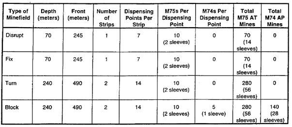
g. Figure 2-9, shows the pattern for Flipper turn and block minefields. These minefields require two centerlines, 170 meters apart. The minefield front is 490 meters and requires 14 dispensing points on each centerline. The total minefield depth is 240 meters. Turn and block minefields require 280 M75 AT mines (56 sleeves) . Block minefields require 140 M74 AP mines (28 sleeves) in addition to AT mines. Optimally, two Flipper dispensers are used to emplace turn and block minefields so that both strips, are emplaced simultaneously. However, one Flipper can emplace both strips, one at a time. Table 2-1, summarizes the site layout for Flipper minefields.
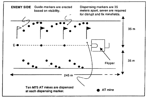
Figure 2-8. Flipper disrupt and fix minefields
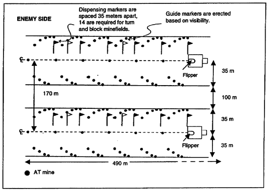
Figure 2-9. Flipper turn and block minefields
Table 2-1. Flipper minefield data
2-8. Recording. When the Flipper minefield is completed, the NCOIC completes a scatterable minefield report as outlined in Chapter 8 of FM 20-32. Figure 2-5, shows the format for completing the scatterable minefield report. The OIC ensures that the report is completed on time and is accurate.
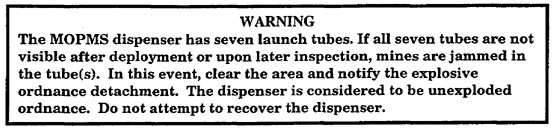
2-9. General. The MOPMS (Figure 2-10) is a man-portable, 162-pound, suitcase-shaped mine dispenser that can be emplaced anytime before dispensing mines. The dispenser contains 21 mines (17 AT and 4 AP) . The mines have finger-like leaf springs along their outer circumference that are designed to push the mine into proper orientation if they land on their side.
Figure 2-10. MOPMS
a. Each dispenser contains seven tubes; three mines are located in each tube. When dispensed, an explosive propelling charge at the bottom of each tube expels mines through the container roof Mines are propelled 35 meters from the container in a 180-degree semicircle (Figure 2-11) . The resulting density is 0. 01 mine per square meter. The safety zone around one container is 55 meters to the front and sides and 20 meters to the rear.
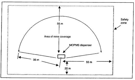
Figure 2-11. MOPMS emplacement and safety zone
b. Mines are dispensed on command using an M71 RCU or an electronic initiating device, such as the M34 hand-blasting machine connected to the container by field wire. Once mines are dispensed, they cannot be recovered or reused. If mines are not dispensed, the container may be disarmed and recovered for later use.
c. The RCU can recycle the 4-hour SD time of the mines three times, for a total duration of approximately 13 hours. Mines with a 4-hour SD time will begin to self-destruct at 3 hours and 12 minutes. All active mines must be recycled within 3 hours of the initial launch or last recycle. This feature makes it possible to keep the minefield emplaced for longer periods if necessary. The RCU can also self-destruct mines on command, allowing a unit to counterattack or withdraw through the minefield, as necessary, rather than waiting until the SD time has expired. The RCU can control up to 15 MOPMS containers or groups of containers from a distance of 300 to 1,000 meters via separate pulse-coded frequencies. Coded frequencies defeat threat electronic countermeasures directed against the system.
d. If the M71 RCU is not available, a direct wire link is used in conjunction with the M32, M34, or M57 blasting machine. By using the M32 10-cap blasting machine, one MOPMS dispenser can be detonated at a maximum range of 1,000 meters. The M34 50-cap blasting machine can detonate one MOPMS at a maximum range of 3,000 meters. (Due to internal resistance, the maximum range is decreased by 400 meters for each additional MOPMS connected in series). The M57 claymore-type firing device can fire only one MOPMS at a maximum range of 100 meters. When controlled by direct wire, MOPMS dispensers cannot be command-detonated, and the SD time cannot be recycled.
2-10. Employment. The MOPMS provides a self-contained, on-call minefield emplacement capability for all forces. It can be command-detonated, reused (if mines are not dispensed) , and directly emplaced to provide complete and certain coverage of small or critical targets. The ability to command-detonate mines or extend their SD time provides an added flexibility not currently available with other scatterable mine systems. With its unique characteristics, the MOPMS is ideally suited for the following minefield missions:
- Closing gaps and lanes in existing minefields.
- Emplacing hasty protective minefields.
- Emplacing deliberate protective minefields (cases emplaced, but mines not dispensed) .
- Emplacing nuisance minefields (trails, crossing sites, landing zones, drop zones, and road junctions) .
- Closing counterattack routes temporarily.
- Supporting ambushes.
- Emplacing tactical disrupt and fix minefields.
- Supporting military operations on urbanized terrain (MOUT).
a. When the MOPMS is used to close lanes, the container is positioned and dispensed by personnel in an overwatching position from a safe standoff. The MOPMS is ideally suited for creating a small disrupt obstacle in support of engineers executing a reserved demolition. Engineers prepare the reserved target for demolition and emplace several MOPMS units on the enemy side, just out of target range. When the last forward elements passes through the target, the firing party detonates the charges. If something goes wrong or the firing party needs more time, MOPMS mines can be dispensed to disrupt the enemy before it reaches the target.
b. The MOPMS provides light and special forces with a versatile, compact system for emplacing nuisance minefields. It can be used in low-, mid-, and high-intensity conflicts and in a variety of environments. Transporting the MOPMS system using a vehicle, helicopter, or fixed-wing aircraft is its major limitation.
2-11. Emplacement. MOPMS dispensers are issued as standard Class V munitions and are drawn from an ammunition supply point on a mission-by-mission basis. RCUs are organizational issues of equipment and are assigned to engineer and combat arms units. Due to the weight of the system, it will normally be transported by vehicle, as close as possible to the emplacement site, where it can easily be hand-emplaced by four soldiers using the four foldout carrying handles.
a. To ensure that the minefield will be dispensed in the proper location, the container should be carefully sited by the NCOIC. Several containers can be used together to provide a greater area of coverage or higher mine density. If mines are not dispensed immediately, containers should be camouflaged and, if possible, buried. When placed in sand or snow, brace containers to prevent them from moving during mine dispensing. Designate a firing point that gives the operator clear observation of the area to be mined. Firing systems must be inspected according to MOPMS operating instructions. If mines are dispensed immediately, remove empty containers to avoid revealing the minefield location.
b. The MOPMS can be employed to emplace disrupt and fix tactical minefields. Emplacement procedures are the same as for protective minefields. However, MOPMS containers are arranged in a specific pattern to achieve the necessary depth, frontage, and density. Once a disrupt minefield is marked (to include the safety zone) , MOPMS containers are arranged as shown in Figure 2-12. The safety zone is 55 meters to the front and sides and 20 meters from the rear of the container. The disrupt minefield uses four MOPMS containers that are spaced 70 meters apart to give a minefield front of 280 meters (not including the 235-meter safety zone) . Other MOPMS containers are offset from the baseline by 35 meters to give the minefield a depth of 70 meters (not including the 235-meter safety zone) . All containers are fired using the same RCU or firing device.
c. Figure 2-13 illustrates the arrangement of MOPMS containers for a fix minefield. The basic layout is the same as the disrupt minefield; however, the fix minefield has one additional MOPMS that is placed 70 meters forward of the baseline to act as an irregular outer edge (OE) . This gives the same 280-meter front but increases the minefield depth to 115 meters (not including the safety zone) .
2-12. Dispenser Operations. Move the dispenser to the proposed minefield site before entering the command and control data into the dispenser. Put the dispenser on the ground with the arrow on top pointed toward the proposed minefield site. This arrow points toward the center of the future minefield. Put the dispenser on sand or snow, bracing it so that it does not move. The NCOIC directs the soldiers to perform the following steps to employ the MOPMS dispenser.
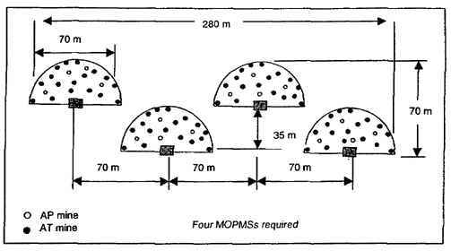
Figure 2-12. MOPMS in a disrupt minefield
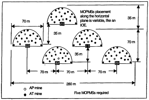
Figure 2-13. MOPMS in a fix minefield
a. Enter the command and control data into the dispenser and arm the dispenser (Figure 2-14).
(1) Turn the RCU on and enter the 4-digit send code. Press the GRP ID key (9) to select the correct group number.
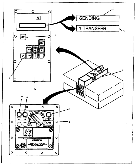
Figure 2-14. Dispenser command and control data loading and arming
(2) Set the dispenser SAFE/ARM switch (6) to TEST. Check to ensure that the BATT OK (7) and the CKT OK (8) lights come on.
(3) Set the dispenser SAFE/ARM switch (6) to LOAD.
(4) Clear all foreign material off the top of the dispenser.
(5) Put the RCU on top of the dispenser. Carefully line up and join the MCDs of the RCU and the module control unit (4) .
(6) Press the TRANSFER key (1) of the RCU. Check to ensure that the SENDING (2) and 1 TRANSFER (3) lights are displayed.
(7) Check to ensure that the DATA IN light (5) is on. This shows that the dispenser has the data.
(8) Turn off the RCU and remove it from the dispenser.
(9) Set the dispenser SAFE/ARM switch (6) to ARM by pushing the switch in and rotating it 1/4 turn clockwise. There is a 5-minute safe time before you can deploy the mines.
b. Deploy mines using the RCU (Figures 2-14 and 2-15).
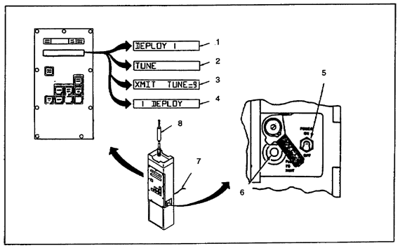
Figure 2-15. Remote control unit
(1) Attach the antenna (8) and the counterpoise cable (7) to the RCU (Figure 2-15) .
(2) Extend the counterpoise cable on the ground toward the dispenser (Figure 2-15) .
(3) Turn the RCU on (5) and enter the 4-digit send code (Figure 2-15) .
(4) Press the GRP ID key (9) (Figure 2-14) until you see the number of the group you want to deploy (1) (Figure 2-15) .
(5) Press the DEPLOY key (10) (Figure 2-14) . Check to see that DEPLOY 1 is displayed (1) (Figure 2-15) .
(6) Press and release the PUSH TO XMIT switch (6) (Figure 2-15) . Ensure that TUNE (2) is displayed for about 1. 5 seconds, and then check to see that XMIT TUNE = n (3) is displayed (Figure 2-15) .
NOTE: The value of n is a measure of good or poor tuning. If n is equal to or greater than 5, you have a good tune. If the BAT LOW U light flashes during transmission, replace the battery immediately.
(7) Verify that 1 DEPLOY (4) is displayed after about 10 seconds (Figure 2-15) .
(8) Turn the RCU off.
2-13. Recording. When the Flipper minefield is completed, the NCOIC will complete a scatterable minefield report as outlined in Chapter 8 of FM 20-32. Figure 2-5, shows the format for completing the scatterable minefield report. The OIC ensures that the report is completed on time and is accurate.
GO TO: