|
RDL Homepage |
Table of Contents |
Document Information |
Download Instructions |
LESSON 4
SITUATIONAL OBSTACLE PLANNING
OVERVIEW
LESSON DESCRIPTION:
This lesson addresses the doctrinal principles for planning, integrating and executing situational obstacles. As an engineer, you must know how to plan and integrate situational obstacles and make accurate survivability recommendations at brigade, TF, and company levels to support the maneuver plan and the commander's intent
LEARNING OBJECTIVE:
| ACTION: | Identify the doctrinal principles and procedures for planning integrating, and executing situational obstacles. |
| CONDITION: | Given the material contained in this lesson. |
| STANDARD: | Correctly answer all questions in the practice exercise at the end of this lesson. |
| REFERENCES: | The material contained in this lesson was derived from the following Field Manuals and material approved for instruction by the US Army Engineer School (USAES): |
INTRODUCTION
Situational obstacles are those that units plan (and possibly prepare) prior to starting an operation, but do not execute unless specific criteria are met. Units may or may not execute situational obstacles, depending on the situation that develops during the battle.
A situational obstacle is a tactical obstacle-emplacing capability held in reserve. It is more of a be prepared mission than an on order mission. Commanders execute situational obstacles in response to immediate tactical requirements and opportunities. They attack an enemy's vulnerability, exploit success, or provide flank protection. Plan situational obstacles for offensive and defensive operations. Planned situational obstacles counter possible enemy reactions to our plan. The plan includes necessary target areas of interest (TAIs), trigger lines, and execution responsibility assignments to ensure successful results. Normally, execution authority remains at brigade, and the brigade engineer structure will be alert for the appropriate intelligence indicators.
Use situational obstacles when lack of time or resources prevents installing all needed obstacles before the battle. Install situational obstacles as temporary solutions after enemy commitment to a specific COA. Normally, employing situational obstacles under these circumstances is a temporary measure used until permanent obstacles can be installed.
Always retain situational-obstacle capability as an obstacle reserve. This allows thickening of obstacle systems in an area where enemy success is greater than expected or where units can handle unexpected AAs. The use of situational obstacles allows the engineer commander to influence the action during the engagement.
The most common situational obstacles are land mines. Land-mine warfare is undergoing a much needed redevelopment process. Manufacturers have made significant improvements in mines and mine-delivery systems. The capability now exists to emplace mines anywhere on the battlefield using various delivery systems. Mine warfare and delivery systems have changed so radically that we now address them by categories-conventional mines and scatterable mines (SCATMINEs). Differences in capabilities, employment techniques, and delivery methods require this separation. Conventional mines refer to those that are hand-laid and require manual arming. They may be buried or laid on the ground surface. Conventional nines are laid in a classic pattern. SCATMINEs refer to those laid without regard to classical pattern. They are delivered by aircraft, artillery, missile, or ground dispenser. SCATMINEs self-destruct after a set period. This lesson addresses only the SCATMINE systems and their use as situational obstacles.
PART A: SITUATIONAL OBSTACLE ASSETS AND CHARACTERISTICS
4-1. Scatterable Mine Systems. SCATMINEs add a new dimension to mine warfare and the battlefield. The traditional concept of large, linear minefields laid across contested areas between two forces is no longer viable, except in desert warfare.
Future battlefields will contain smaller mined areas deployed in response to enemy dispositions and movement. We can employ SCATMINEs against enemy units anywhere on the battlefield. SCATMINEs significantly reduce manpower requirements associated with mine warfare. They are lighter, smaller, and more lethal, and they reduce logistical requirements due to reduced bulk weight. The SCATMINE systems now available to the commander are the Gator, the Volcano (air and ground), the ground-emplaced mine scattering system (GEMSS), the Flipper, the modular pack mine system (MOPMS), and the area denial artillery munitions/remote antiarmor mine system (ADAM/RAAMS).
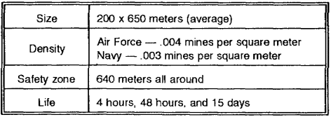
a. Gator. The Gator (see Figure 4-1) is the longest range SCATMINE system emplaced by tactical aircraft. The Gator provides the capability for deep battlefield emplacement of land mines. The Air Force and Navy are the two primary dispensing agencies. Each service packages the Gator differently. The Air Force's cluster-bomb canister unit holds 94 mines (72 AT and 22 AP). The Navy's canister unit holds 60 mines (45 AT and 15 AP). The Gator delivery system is compatible with the Air Force's A-10, F-4, F-16, and F-111 aircraft and the Navy's A-6, A-7, F-4, and F-16 aircraft The maximum delivery speed is 800 knots at 250 to 5,000 feet in altitude. The size of the minefield (see Figure 4-2) depends upon the aircraft's speed and altitude; density depends upon the number of canisters dropped. Table 4-1 contains minefield data for the Gator.
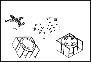
Figure 4-1. Gator
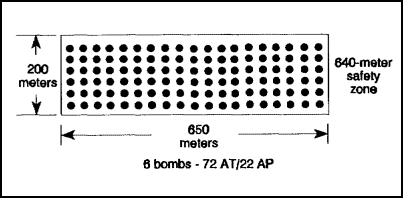
Figure 4-2. Gator minefield
b. Volcano (Air). The air Volcano (see Figures 4-3 and 4-4) is a heliborne system using side-mounted dispensing racks on a Blackhawk helicopter. Using this dispensing system requires prior planning. When the Army resourced the system for the aviation brigade, it only gave them the capability to install the dispensing system. It requires additional manpower to mount the canisters. Normally, engineers mount and control Volcano canisters. Each canister contains a ratio of five AT mines to one AP mine. Table 4-2 contains minefield data for the air Volcano.
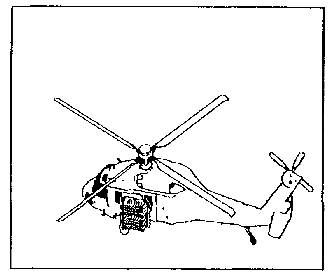
Figure 4-3. Volcano (air)
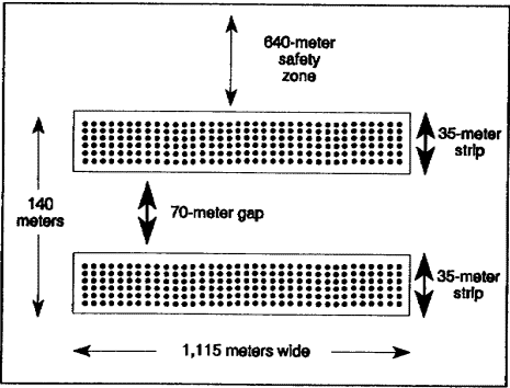
Figure 4-4. Volcano (air) minefield

c. Volcano (Ground). The ground Volcano (see Figures 4-5 and 4-6) is the same system as the air Volcano except that it mounts in the bed of a 5-ton truck or M548 tracked cargo carrier. The launcher consists of four racks holding 40 mine canisters each. Two racks point to one side of the vehicle and two point to the opposite side. It dispenses the mines 25 to 60 meters away from the vehicle at ground speeds of 5 to 55 miles per hour (mph). Other characteristics of the system are shown in Table 4-3.
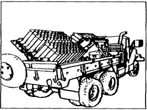
Figure 4-5. Volcano (ground)
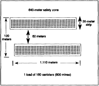
Figure 4-6. Volcano (ground) minefield
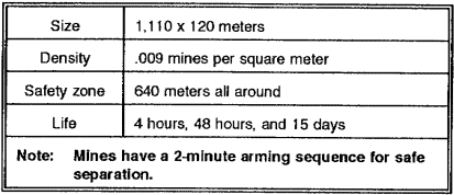
d. Ground-Emplaced Mine Scattering System (GEMSS). There are very few GEMSS (see Figures 4-7 and 4-8) left in operation. Most of them can be found in Germany. The GEMSS works like a rotating tire that pitches the mines. Two magazines feed the mines down a chute and spins them out at different angles and widths, depending on the setting. Each magazine holds up to 400 mines. These mines have a 45-minute arming time which is a significant drawback when targets of opportunity arise quickly. Table 4-4 contains minefield data for the GEMSS.
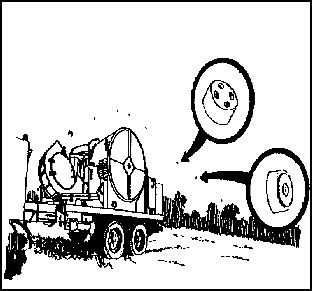
Figure 4-7. GEMSS
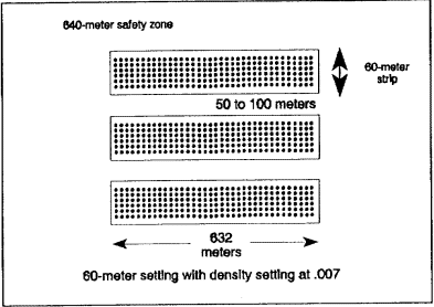
Figure 4-8. GEMSS minefield
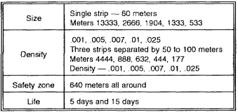
e. Flipper The Flipper replaces the GEMSS (see Figure 4-9). The Flipper is a manually-fed system mounted on an APC, an M548, a commercial utility cargo vehicle (CUCV), a high-mobility multipurpose wheeled vehicle (HMMWV), or a 2 1/2- or 5-ton truck. The Flipper uses the same mines as the GEMSS. One soldier and an assistant operate the system. The mine-dispensing rate is six mines per minute at a speed of 1 mph. The soldier in back of the vehicle (the flipper) fires a mine every 10 seconds. The soldiers work in teams to get proper density and depth for the minefield (see Figure 4-10). The minefield data for the Flipper depends on the logistical availability of Flippers.
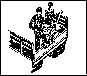
Figure 4-9. Flipper

Figure 4-10. Flipper minefield
f. Modular Pack Mine System (MOPMS). The MOPMS is a man-portable, 102-pound, suitcase-shaped mine dispenser (see Figure 4-11). It has a mix of 17 AT and 4 AP mines. You may connect it to a blasting machine or a remote control. The remote control handles up to 15 units as far away as 100 meters. The remote range decreases when additional unit are added. The system propels mines 35 meters in an approximate 180-degree semicircle. The self-destruct time depends on internal battery power. Minefield data for the MOPMS is shown in Table 4-5.
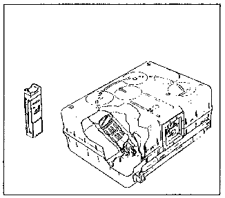
Figure 4-11. MOPMS
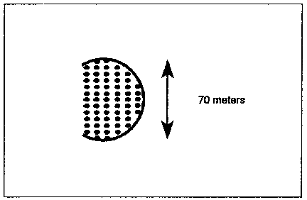
Figure 4-12. MOPMS minefield

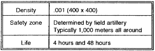
g. ADAMs and RAAMS. The ADAM system contains 36 mines and the RAAMS contains 9 mines (see Figures 4-13 and 4-14). Field artillery M109 and M198 howitzers deliver these mines. An artillery battalion's basic load is one 400- x 400-meter, medium-density mission. This equates to 34 ADAMs and 24 RAAMS rounds per gun tube. Minefield data is shown in Table 4-6.
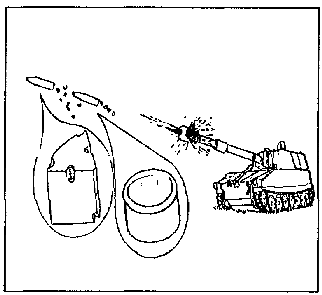
Figure 4-13. ADAM/RAAMS
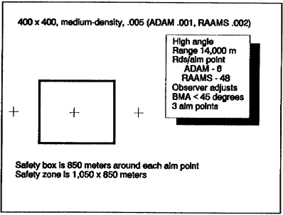
Figure 4-14. ADAM/RAAMS minefield
4-2. Antipersonnel and Antitank Scatterable Mines.
a. Antipersonnel Scatterable Mines. We employ two types of AP SCATMINEs--one type is used with the ADAM and the other is used with the Gator, Volcano, and GEMSS.
The ADAM AP mine is a wedge-shaped bounding fragmentation mine that is 2.75 inches high and weighs 1.2 pounds. It has seven trip wires; a minimum of three trip wires will extend six meters from the mine. These trip wires activate at 0.9 pounds of pressure. The mine bounds two to six feet in the air and creates a lethal killing radius of six to ten meters.
The Gator, Volcano, and GEMSS AP mines are similar in design. They kill through blast and fragmentation. They contain eight trip wires and deploy a minimum of four trip wires 12.2 meters from the mine. As with the ADAM, the trip wires will activate at 0.9 pounds of pressure. The lethal killing radius is 15 meters.
b. Antitank Scatterable Mines. The AT mines employed in the RAAMS, GEMSS, Flipper, MOPMS, and Volcano are generic and have similar functional characteristics. The mines weigh about four pounds and have a magnetic-induced fuze. The warhead is bidirectional and kills by a self-forging fragmentation (SFF) warhead. The fuze detonates as a magnetic field (tank) "peaks" over the mine. The RAAMS, GEMSS, Flipper, and MOPMS AT mines have antidisturbance devices built into 20 percent of them. These AT mines self-destruct at 80 to 100 percent of their self-destruct time. There is only a one-in-a-thousand chance that a live mine will exist after 80 percent of its self-destruct time. The Volcano and Gator AT mines will also self-destruct due to any change in their orientation to the earth's magnetic field.
4-3. Scatterable Mine Effects and Tactical Obstacle Intents. As with conventional minefields, SCATMINE systems disrupt, turn, fix, and block. These are the standard obstacle effects in relationship to the enemy's ability to maneuver. Just like the standard disrupt, turn, fix, and block minefields, we have to tailor SCATMINE minefields to have specific effects on the enemy. One variable we can change with most SCATMINE minefields is the density. The density determines lethality and produces the desired obstacle effects.
a. Density and Lethality.
(1) Disrupt. Required lethality and densities are low (10- to 30-percent lethality). We do not want to expend a lot of effort or materials to accomplish this effect. Just like the standard disrupt minefield's effect on an MRC, we must affect half of the targeted unit's frontage by forcing him to commit bypass or breach assets.
(2) Turn. Turning requires higher densities or more lethal minefields (60- to 100- percent lethality). Depending on the system, subtle orientation that could force the enemy to a different approach could be hard to build. The turn must affect one-third of his formation. From overhead, the entire obstacle group could look like steps, gradually leading the enemy formation down them.
(3) Fix. Fixing requires medium density (30- to 60-percent lethality). With certain systems, achieving a fixing intent is difficult. For example, an ADAM/RAAMS minefield might prevent the enemy from entering the proposed EA. In other words, we sacrifice enticing him into the obstacle. With the fixing intent, massing fires is critical. It requires reducing safety zones around the obstacle which could reduce the amount of weapon systems needed to overwatch the area.
(4) Block. The blocking goal is to deny the enemy the AA. This requires 100-percent lethality. SCATMINE systems reinforce other obstacles to help stop breaching attempts and to force the enemy to use different breaching assets.
b. Obstacle Effects.
(1) Gator. The standard Gator minefield (see Figure 4-15) achieves a disrupt or fix obstacle effect when its orientation is perpendicular to the enemy's AA. Use the Gator frontage of 650 meters for a disruptive obstacle group straddling a 1,300-meter-wide (or less) AA. This targets half of the enemy's formation. The same applies to a fixing obstacle group except that fixing obstacles must cover the entire AA. This limits the Gator's use to AAs less than 650 meters. In order to achieve the appropriate lethality associated with turn and block, the Gator minefield's orientation has to parallel the enemy's AA. This limits the Gator for this intent to an AA with a width of 200 meters or less. The best way to use Gator in the turn or block role is to reinforce existing conventional minefields.
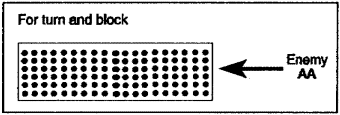
Figure 4-15. Standard Gator minefield
(2) Volcano. One Volcano minefield (air or ground) can achieve a disrupt or fix intent on AAs with widths of 2,000 meters (disrupt) and 1,000 meters (fix). The ground Volcano offers more flexibility in tailoring minefield frontages to achieve specific effect. In order to achieve a turn or block, two Volcano minefields are required. The Volcano, like the Gator, can reinforce the same conventional minefield.
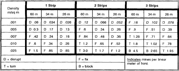
(3) GEMSS. Construct GEMSS like the standard minefield. For a disrupt or fix effect, use a 250-meter frontage. For a turn or block effect, use a 500-meter frontage. It can also have a variety of settings and width patterns, as shown in Table 4-7. The key to GEMSS minefield obstacle effects is not just lethality; for block and turn effects, the minefield depth is critical in destroying and denying the enemy the AA (see Table 4-8).
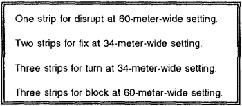
(4) Flipper. Construct the Flipper minefields to match the standard minefields. The conventional minefield frontage, density, and number of rows applies. It takes two strips to achieve a disrupt or fix effect (see Figure 4-16) and four strips for turn or block intents. The dispensers work in parallel. The key is developing a standard drill for the Flipper; 6-meter spacing with a drag-line marker is recommended. This does not achieve 0.5 density, but the mines for the Flipper have greater lethality, thus reducing the needed density. The Flipper uses the same minefield pattern to achieve a turn or block intent.
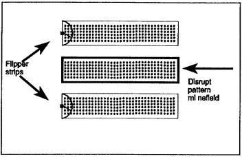
Figure 4-16. Flipper minefield
(5) MOPMS. The relatively small frontage (250 meters) limits the MOPMS obstacle effect. However, you can use multiple MOPMS for a disrupt or fix minefield. Calculations determine the number of minefields required for the obstacle group and substitute four MOPMS for each fix or disrupt minefield. For example, a disrupt obstacle group is straddling a 1,500-meter-wide AA. The density factor for disrupt is 0.5. The amount of linear effort for this group is 750 meters. To obtain the desired number of minefields, divide 750 by the standard disrupt-minefield frontage (250 meters). The result is three minefields. Multiply three by the four MOPMS required for each standard minefield, and the result is 12 MOPMS required. It requires 24 MOPMS for a fix obstacle group straddling a 1,500-meter AA.
(6) ADAMs/RAAMS. ADAMs/RAAMS obstacle effects depend on the AA width and the target depth. The densities directly relate to obstacle effects (see Table 4-9). For a disrupt or fix effect, the frontage depends on the AA and the target depth. For a turn and block effect, the frontage straddles the entire AA. Use ADAMs/RAAMS to reinforce existing obstacles. Engineers need only specify the target and its location, effect, and duration of life. Artillery determines whether it can be fired.
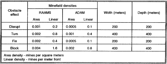
4-4. Logistics. Logistics is a problem that engineers cannot ignore. Elimination of most logistics problems simply requires using common sense. For air Volcano, it is a different story. The engineer must work out the details for loading the canisters. Regardless of the mine locations, this is an engineer function. Loading is time-consuming normally, the aviation personnel want the mines loaded at the last possible minute because of other missions. Establish a forward area rearm/refuel point (FARP) for air Volcanos and Blackhawks. It is necessary to provide manpower to the supply point for loading the canisters. For ground Volcanos on a drop-side, 5-ton truck, use the same procedures as for row minefields. The GEMSS also presents a problem. We have to consider reloading and minefield construction at the same time. We do not want to stop in the middle of constructing a minefield to reload canisters. It takes 45 minutes to arm a GEMSS, which could place soldiers in a dangerous situation. Give Flipper the same consideration.
4-5. Siting and Executing.
a. Air-delivered SCATMINEs require additional and detailed coordination. Mark and site proposed locations for minefields with direct-fire systems. Rehearsal runs are key to preventing errors and ensuring correct siting. Figures 4-17 and 4-18, show initial points (IPs), approach markers, and start and end markers. Figure 4-17 is a TF sector showing an IP, an approach marker, and aircraft panel markers. Figure 4-18 shows how you can use the same IP across the brigade sector. It also shows the Class IV/V supply point where you will load the Blackhawk before its run. Give an update on the situation to the pilots as they await the loading of their aircraft. For siting and executing air-delivered SCATMINEs (ADAMs/RAAMS), perform the following functions:
- Confirm grid coordinates of the center point or aim points.
- Place weapon systems to cover the corner points. Safety zones may require longer-range direct-fire systems.
- Minimize safety zones.
- Execute at a time based on the firing unit size. The sustainment rate of fire is 1 round per minute.
- - Register fires.
- Use the global positioning system (GPS).
For siting and executing air-delivered SCATMINEs (the Gator and the air Volcano), perform the following functions:
- Site the proposed trace of the obstacle.
- Establish visual and radio signals for the minefield's approach, orientation, and start.
The Gator requires a ground-forward air comptroller (GFAC). This asset is normally retained at division level. The air Volcano requires the following:
- An engineer in the Blackhawk (situation dependent).
- Rehearsal runs to decrease emplacement errors.
- Critical planning points or markers.
- - Initial point-usually an easily identifiable terrain feature for coordination of the entry point of the Blackhawk.
- Approach marker--air panel or flag (marker visible from the air for the Blackhawk to set altitude, air speed, and final orientation.
- Start and end of minefield markers--markers visible from the air.
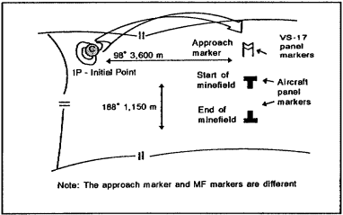
Figure 4-17. Siting and execution
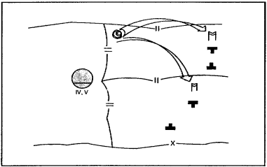
Figure 4-18. Siting and execution
b. Executing the ground-emplaced SCATMINE resembles executing the row minefield (see Figure 4-19). Ensuring minefield emplacement at the desired location is critical. A GPS helps, as does registering the target. For siting and executing ground-emplaced SCATMINEs, perform the following functions:
- Trace all minefield sites with direct fires.
- Mark the center line of the ground Volcano.
- Mark each strip and install a drag-line marker for each prime mover for the Flipper system.
For siting and executing the GEMSS, perform the following functions:
- Mark the center of the strip for setting A.
- Mark the center line of the vehicle for setting B.
- Mark the left or right limit for setting C.
Building additional strips for the GEMSS and the Flipper requires accurate planning of the minefield width, the vehicle load, the density, and reload times. You must ensure that they do not conflict with arming times.
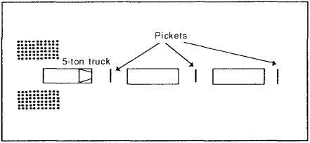
Figure 4-19. Ground-emplaced SCATMINEs
4-6. Marking and Recording/Reporting Scatterable Mine Minefields.
a. Marking. Emplacing SCATMINE minefields remotely and rapidly throughout the battlefield presents a real problem with regard to marking. SCATMINE minefield marking may not be needed or may be impossible in many cases. SCATMINEs emplaced in enemy territory are prime examples.
Mark SCATMINE minefields to the extent needed to protect friendly troops. Mark those emplaced in friendly territory according to standard marking procedures. Mark those emplaced in forward areas on the friendly side and the flank. Mark minefields emplaced in rear areas on all sides.
No specific marking system exists for SCATMINE minefields. Use the standard marking procedure for standard minefields for some SCATMINE systems (such as the GEMSS) that have specific and known limits (see Table 4-10). Other systems have less definable limits and will not normally be marked due to their employment in enemy territory. Figure 4-20 shows an example of marking a Volcano minefield.

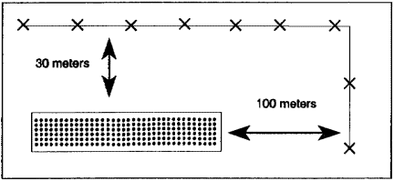
Figure 4-20. SCATMINE marking--Volcano
b. Recording and Reporting Accurate, timely, and uniform recording and dissemination of SCATMINE minefield emplacement information is a must. Fluid and fast-moving tactical situations require that we have complete information on SCATMINE employment and pass it on in a simple and rapid manner to all affected units. Also, recording SCATMINE minefields helps clearing operations after the war. The variety of emplacing systems and units precludes the use of locally devised reporting and dissemination methods. Do not record SCATMINEs in the same detail required for conventional mines. The locations of individual SCATMINEs are unknown so you cannot and need not plot them as you would conventional mines. The aim points, corner points, and type of mines employed are basic information that must remain on file for future reference and use.
Tables 4-11 through 4-15, show the reporting and recording procedures used for SCATMINEs. It applies to all delivery systems and can be sent in a voice, digital, or hard-copy mode. Information in the reports varies with the types of emplacing systems. Some systems (such as ADAM/RAAMS, the Gator, and the MOPMS) are point oriented with safety zones calculated from one or more aim points. Other systems (such as the GEMSS) have distinct minefield corner points that you must report. This procedure provides one method that is uniform with all the basic information required to report and maintain a record of SCATMINE employment. This procedure also contains all information needed to warn affected units. You can easily extract warning information and disseminate it to units which require it.
The unit emplacing the mines will immediately report the pertinent information by the most expeditious and secure means. If the initial report is not a hard-copy report, the emplacing unit must prepare the report in hard copy as soon as possible. Send the report through operational channels to the headquarters authorizing the minefield. Post the information on operations maps and disseminate them to affected units. Then forward the report to the senior engineer in the theater for permanent retention. Forwarding the hard copy to the theater commander is not time sensitive. You can also batch reports and forward them when time permits.
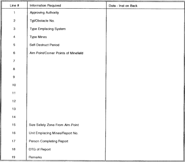
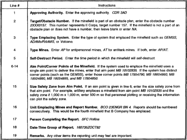
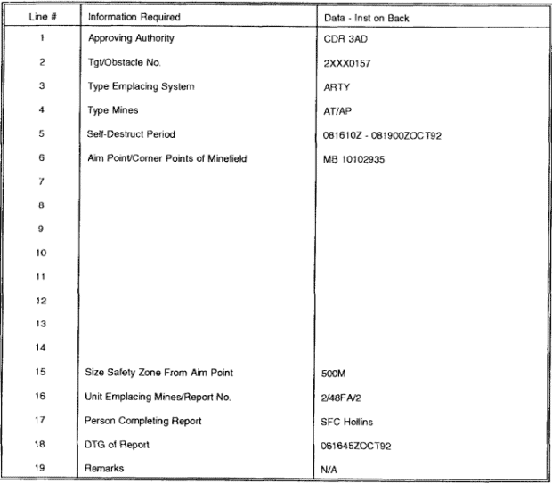
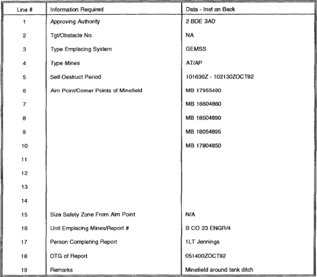
c. Scatterable Minefield Warning (SCATMINWARN). Warn units of the emplacement of SCATMINEs. Disseminate this warning message before or after emplacing the mines. Include only the very basic information to prevent tying up communications systems. Table 4-15 shows a conventional procedure that provides all of the needed information. The Operations and Training Officer (US Army)(S3)/G3 is responsible for disseminating the report.

PART B: SITUATIONAL OBSTACLE PLANNING PROCESS
Before focusing on the planning process, we must review a few basics covered earlier in the lesson.
A situational obstacle is an obstacle-emplacing capability held in reserve. It is more or less a be prepared mission rather than an on order mission. Situational obstacles are executed in response to immediate tactical requirements and opportunities. Use them to attack an enemy's vulnerability, exploit success, or provide flank protection. Offensive and defensive operations involve planning for situational obstacles. Preplanned situational obstacles handle possible enemy reactions to our plan. Examine these reactions during the war-gaming process at every level; they help counter enemy reaction. The plan includes needed TAIs, trigger lines, and execution-responsibility assignments to ensure successful results. Normally, execution authority remains at brigade level, and the brigade engineer structure will be alert for the appropriate intelligence indicators.
Use preplanned situational obstacles when lack of time or resources prevents installing all needed obstacles before the battle. Situational obstacles are temporary solutions. Install them after you determine that the enemy has committed to a specific COA. Normally, employing situational obstacles under these circumstances is a temporary measure used until you can install permanent obstacles.
Always retain situational obstacle capability as an obstacle reserve to allow thickening of obstacle systems in an area where enemy success is greater than expected or to handle unexpected AAs. This allows the engineer commander to influence the action during the engagement.
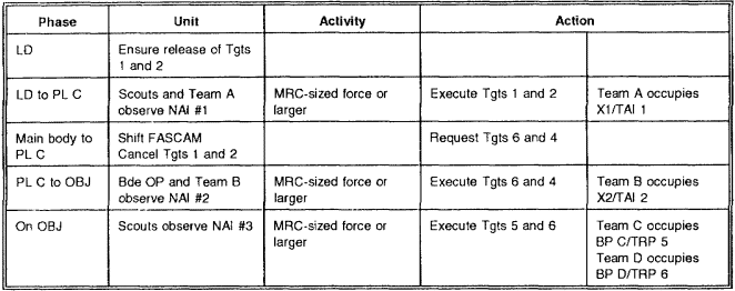
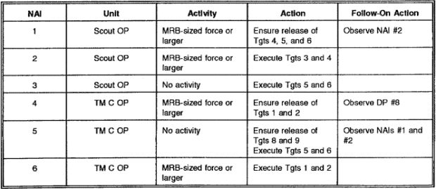
4-7. Situational Obstacles - Offense. Protecting the flanks is the standard situational obstacle use in the offense. Isolating the objective area is also a key use of situational obstacles, especially if you locate the counterattacking force. While moving toward the objective, use situational obstacles to disrupt enemy operations. Sealing AAs as the enemy retreats is another good use. With every successful offensive operation, there is a hasty defense of the objective. Situational obstacles aid in this transition. Figure 4-21 and Table 4-16 show an example of offensive situational obstacle employment.
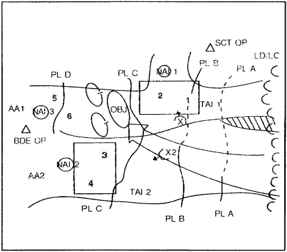
Figure 4-21. Situational obstacles--offense
4-8. Situational Obstacles - Defense. If CAS and artillery are available, use their mine-delivery systems for situational obstacles for deep preparation of EAs to achieve the disrupt or fix effect. Disrupting the enemy forward in the sector and weighting the main effort are other uses for situational obstacles. Along the same lines, shifting the main countermobility effort is another possibility. Assisting in an economy of force, separating enemy echelons, closing lanes, and reseeding breached lanes are other uses. Figure 4-22 and Table 4-17, show an example of situational obstacle deployment in the defense.
4-9. Situational Obstacle Planning Cell. The planning cell is almost the same as the one discussed in Lesson 3; however, the focus is different. The commander gives guidance, priorities, and authority. He also approves the use of situational obstacles. The S3 pulls the TF's battle staff together to ensure support for the scheme of maneuver. The S3 works subunit mission responsibilities into the OPORD, develops the scheme of maneuver, and incorporates obstacle intents and effects. The S2 aids in developing situational obstacle targets, effects, and timing. The fire-support officer (FSO) develops detailed ADAM/RAAMS planning and coordination and, like any other obstacle, covers it by fire. The Gator requires Air Force liaison and the air Volcano needs aviation brigade liaison.
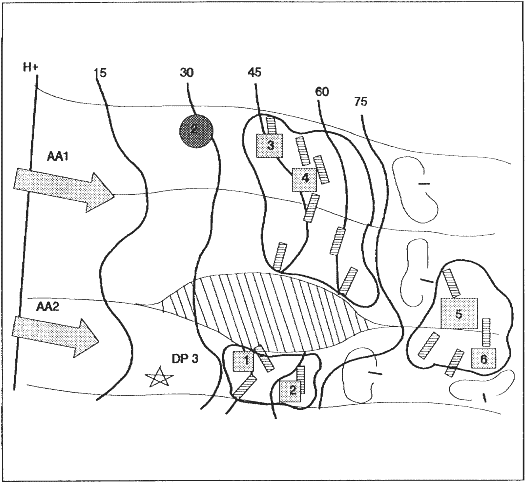
Figure 4-22. Situational obstacles--defense
4-10. Tactical Planning Process. The decision-making process provides the basic format for the planning process. The left column of Table 4-18 contains the situational-obstacle critical planning steps. The right column contains the steps in the decision-making process where we develop the critical information.
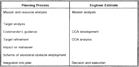
a. Mission and Resource Analysis. Receiving the mission is the first step and should reveal the commander's intents. Determine the available assets from the engineer battlefield assessment (EBA). Included in the analysis are the following:
- Resources allocated by higher headquarters.
- Higher headquarters commander's intent for employing FASCAM.
- Higher headquarters mission.
- Higher headquarters intent for future operations.
(1) Synchronization tools. Look for the synchronization tools used as part of mission analysis. They aid in getting the right assets to the right location at the right time. These tools include the following:
- The SITEMP.
- The maneuver plan (near and far).
- The execution matrix.
- The scheme of engineer operations.
- The scheme of indirect-fire integration.
- The reconnaissance and surveillance (R&S) plan.
- The event template.
- The decision-support template (DST).
(2) Mission analysis. Mission analysis tells the who, what, where, and when of the operation. Analysis is critical for situational obstacle planning. The following procedures should be accomplished during the mission analysis:
- Identify the target/situation.
- Trigger obstacle execution.
- Emplace the obstacle.
- Cover the obstacle.
- Report the completion.
b. Target Analysis. As with any tactical obstacle, the analysis should have three parts: a specific target, a specific effect, and a relative location. The target analysis is a key activity for the engineer and the S2. The engineer must look at the SITEMP and pull out the needed information. If the information is not posted, the engineer must be bold enough to ask the right questions to obtain the needed information.
Target analysis is based on the scheme of maneuver, the obstacle intent/plan, and the following items from the SITEMP:
- Counterattack axis.
- Mobility corridors.
- Avenues of approach.
- Likely enemy COA.
- Available intelligence.
- Windows between echelons.
Targets are nominated during COA development.
c. Commander's Guidance. The commander's guidance is critical. How does he want to use situational obstacles, if at all? He should include his targeting priorities, execution or commander's criteria, and desired effects (disrupt, turn, fix, and block).
d. Target Refinement. During the course of development, you designate the use of situational obstacles and then refine your plan. Include the three subcomponents of obstacle intents. Armed with these three components, develop the composition of the situational obstacles (including needed frontage and densities to match the target, AA, and obstacle effect). Conflicts might arise, especially with indirect-fire support on targets of opportunity for ADAMs/RAAMS use. Commit Blackhawks for logistical or troop movements.
e. Impact on Maneuver. Look at the total plan and analyze the impact on friendly maneuver (near and far term and adjacent units). Understand the total plan and the commander's intent two levels up. In the defense, consider plans to go on the offensive, counterattack, relief-in-place operations, and forward passages. In the offense, consider plans to continue the attack, consolidate on the objective, conduct forward passages, and change the direction of the attack.
f. Scheme of Situational Obstacle Employment. Identify the trigger action for execution of the situational obstacle. Annotate this trigger action in the DST. As with most operations, use the reverse planning process to ensure that the assets get there on time.
g. Integrate Situational Obstacles into the Plan. This is the point where the entire plan comes together. At this point, you should finalize coordination with other staff officers. You must ensure timely dissemination of all situational obstacle graphics and matrices to key leaders. Discuss the execution of your plan at all briefings and rehearsals.
4-11. Summary. This lesson addressed the basic and doctrinal principles for planning, integrating and executing situational obstacles to support offensive and defensive operations. The lesson pointed out that a situational obstacle is an obstacle-emplacing capability held in reserve. It is more a "be prepared mission" than "on order." We execute situational obstacles in response to immediate tactical requirements and opportunities. We use them to attack an enemy's vulnerability, exploit success, or provide flank protection. Offensive and defensive operations involve planning for situational obstacles. Preplanned situational obstacles handle possible enemy reactions to our plan. Examine these preplanned obstacles during the war-gaming process at every level and design them to counter enemy reaction. The plan includes needed TAIs, trigger lines, and execution-responsibility assignments to ensure successful results. Normally, execution authority remains at brigade level, and the brigade engineer structure will be alert for the appropriate intelligence indicators.
Use situational obstacles when lack of time or resources prevents installing all needed obstacles before the battle. Situational obstacles are temporary solutions. Install them after determining that the enemy has committed to a specific COA. Normally, situational obstacle employment under these circumstances is a temporary measure used until permanent obstacles are installed.
Always retain a situational obstacle capability reserve to allow thickening of obstacle systems in an area where enemy success is greater than expected or to handle unexpected AAs. This allows the engineer commander to influence the action during the engagement.
The most common situational obstacles are land mines. Land-mine warfare is undergoing a tremendous redevelopment process. Significant improvements have been made in mines and mine-delivery systems. The capability exists to have mines emplaced anywhere on the battlefield using various delivery systems. Mine warfare and delivery systems have changed so radically that we now address them by the categories--conventional mines and SCATMINEs. The differences in capabilities, employment techniques, and delivery methods requires this separation and categorization.
Conventional mines refer to those mines that do not self-destruct. Emplace conventional mines by hand or using mechanical mine-laying equipment. Bury them or lay them on the ground. Lay conventional mines in a classic pattern or without regard to form or pattern, depending on the tactical situation. Scatterable mines refer to self-destructing mines. These mines self-destruct after a set period.
Effective employment of situational obstacles is a key element in any tactical plan. Properly sited and planned situational obstacles provide the commander with a significant advantage in offensive and defensive operations. The obstacle planning process must be systematic, coordinated, and fully integrated with the overall tactical plan. Involve all elements of the combined arms team in the planning and employment process to exact the greatest cost from the enemy. As an engineer, you must understand the basic principles of denial operations to plan and integrate situational obstacles and to make accurate survivability recommendations at the brigade, TF, and company levels to support the maneuver plan and the commander's intent.
Practice Exercise

