|
RDL Homepage |
Table of Contents |
Document Information |
Download Instructions |
LESSON 3
OBSTACLES AND SURVIVABILITY PLANNING
OVERVIEW
LESSON DESCRIPTION:
This lesson addresses engineer obstacle and survivability planning including how to develop an obstacle plan and make recommendations to the maneuver commander at brigade, TF, and company levels. The primary focus is on obstacle intent direct- and indirect-fire analysis, obstacle synchronization, and the integration of survivability effort into the obstacle plan.
LEARNING OBJECTIVE:
| ACTION: | Identify levels of responsibility for obstacle planning obstacle planning considerations, elements of the obstacle planning process, and how the plan is developed. |
| CONDITION: | Given the material contained in this lesson. |
| STANDARD: | Correctly answer all questions in the practice exercise at the end of this lesson. |
| REFERENCES: | The material contained in this lesson was derived from the following Field Manuals and material approved for instruction by the US Army Engineer School (USAES): |
INTRODUCTION
Effective obstacle employment is a key element in any tactical plan. Obstacles that are sited properly provide the commander with a significant advantage in both the offense and the defense. Planning and emplacing obstacles cannot be approached haphazardly. The process must be systematic, coordinated, and fully integrated with the tactical plan. All elements of the combined arms team must be involved in planning and employing obstacles in order to extract the greatest benefits for the friendly force and to inflict the greatest damage on the enemy.
PART A: FUNDAMENTALS OF OBSTACLE PLANNING
3-1. Obstacle Planning. The engineer estimate provides the planning framework for the division engineer and his staff in supporting both offensive and defensive operations. However, the engineer-estimate steps focus differently on the mission aspects respectively. For both operations, the division engineer and his staff involve themselves in identifying missions, allocating resources, and synchronizing and controlling engineer functions. Countermobility and survivability are the primary missions that drive engineer forces, resource allocation, and synchronization. Therefore, planning for countermobility and survivability consumes the majority of the division engineer's time. Due to this concentration on countermobility and survivability planning, the engineer estimate is refined into the obstacle planning process. Figure 3-1 shows the interrelationship of the obstacle planning process and the engineer estimate.
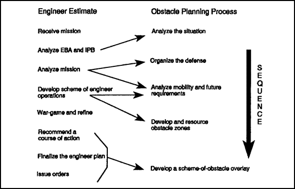
Figure 3-1. Engineer estimate and obstacle planning process
The obstacle planning process does not preempt the use of the engineer estimate. The engineer estimate provides the total integration of the engineer functions (mobility, countermobility, survivability, topographic, and general engineering) into the division's planning process.
Before the actual obstacle planning process can be discussed, you must understand the planning considerations and echelons of obstacle planning and control.
3-2. Obstacle Planning Considerations. Obstacles must support present and future tactical plans, be logistically supportable, and be fully coordinated. The items listed in paragraphs a through j below mirror the planning process and should be considered before developing an obstacle plan. Consider these items for both offensive and defensive operations. These considerations will provide a workable, realistic, and coordinated approach to planning obstacle employment.
a. Assigned Mission. The mission is the primary consideration in obstacle planning. It is a clear, concise statement of the purpose of the task to be accomplished by the command. It tells the command the "who," "what," "where," and "when" of an operation. Mission analysis is critical in planning obstacles. The "who" portion and its accompanying task organization allocates resources to do the job; the "what' specifies the type of operation (such as defend, attack, or delay); "where" outlines the AO; and "when" specifies the time available and establishes deadlines.
During the planning phase, much or all of this information will be verbal, based upon the commanders analysis of the mission received from higher headquarters. The estimate, the eventual plan, and the execution are based upon tasks contained in the mission.
Directed and reserve obstacles are of prime importance to the overall mission and should be planned first. You must know the authority and time of execution.
While obstacle employment supports the current mission, it should not impede future plans or missions. This may not be possible in every instance. For example, emplacing an artillery-delivered minefield upon an attacking enemy may be the right thing to do, even though an attack through the area was planned prior to the self-destruction of the minefield. You must weigh the pros and cons.
b. Terrain and Weather. These factors and their effects are critical in answering the following questions: Where are good existing obstacles? Are they within the enemy's AA? Are they effective when tied in with reinforcing obstacles? Are they within range and fields of fire of friendly weapons? What are the anticipated weather conditions? Is the soil frozen? Is digging possible? Can mines be buried?
c. Avenues of Approach. The commander must visualize the AAs under all conditions. He must also determine the size of friendly or enemy forces that those avenues can support.
d. Engagement Areas, Battle Positions, and Locations of Weapon Systems. A good analysis will show where the best areas are for friendly weapons to engage the enemy. With this analysis, you can also ascertain the most likely areas where friendly forces can expect to be engaged by enemy direct weapons. The process is essentially the same in the defense and the offense. Existing obstacles, fields of fire, and natural cover and concealment are key considerations for determining where to best engage the enemy or expect to be engaged.
e. Obstacle Locations and Types. The selection of EAs and battle positions must be considered before planning reinforcing obstacles. Once EAs and battle positions have been selected, the commander and engineer select and site reinforcing obstacles. This process is unconstrained, so the commander and engineer will select and site all of the reinforcing obstacles needed without regard to manpower, time, and logistics. This selection process will determine what needs to be done in order for the obstacle system to be most effective. What needs to be done usually requires more effort than resources available. The process provides the commander and the engineer with a method to establish priorities If resources are constrained.
f. Commander's Obstacle Priorities. Once the unconstrained obstacle estimate has been done, the commander establishes priorities for obstacles. By seeing what needs to be done, he chooses those obstacles that must be emplaced. Through this process, the engineer is given direction to employ resources knowing the effort is expended on those obstacles most critical for accomplishing the command's objectives. The type, proposed location, and purpose of the obstacles will depend on an offensive or defensive plan. However, the basic thought process remains constant.
g. Resources. The commander and the engineer consider the assets available to construct, guard, and execute obstacles. Engineer assets are limited, and the priority of work may be given to only a portion of the planned AO. The engineer takes the commander's priorities and makes an estimate based upon time, manpower, equipment, and logistics. The engineer must know how much of each resource is required to emplace and execute a given obstacle. This estimate is based upon the type of obstacle, the soldier's experience, the state of training and the equipment's condition. Standard obstacle factors (outlined in FM 5-102) may be used to assist in the estimate process. They are only a guide and should be altered based on the conditions existing at the time of the estimate.
Another consideration is the commander's decision on who will guard and detonate obstacles not detonated immediately after emplacement. Essentially, the commander has two choices--either use engineers or use soldiers from maneuver units. If engineers are used, then engineer assets are used up quickly, thus limiting the number of obstacles that can be emplaced as the battle progresses. The same can be said for using soldiers from maneuver units. This difficult decision must be made early enough for the engineer and maneuver units to properly plan. In any case, the target-turnover process must be trained and rehearsed during combined arms training so that the commander has some latitude in decision making.
The time available to accomplish the obstacle mission is an important consideration. Lead time is required to gain the obstacle density needed in the obstacle plan. Emplacement time varies with the types of obstacle. For example, it takes more man-hours to emplace a conventional tactical minefield than to create a road crater. Emplacement lead time falls into two categories: time required to construct the obstacle and time required to get materials to the obstacle location. The latter may require twice as much tine as the actual construction. The loss in productivity due to logistics time can be reduced by allocating additional transportation support to engineer units. In most cases, the engineer squad's truck or APC must serve as the personnel carrier (mobility) and cargo carrier (resupply). Another way to increase production is to work maximum hours. However, this pace can be maintained for only a few days before soldiers and equipment begin to fail.
Finally, logistics matters must be considered. The commander must set priorities for the delivery of munitions and materiel. He must allocate the available haul assets among ammunition, obstacle materials, and other critical supplies. Among obstacle materials, difficult choices must be made. A conventional tactical minefield can take up to 100 times the haul assets of a point obstacle. Yet, the minefield may be the only effective obstacle in the situation. To lessen the haul requirements, engineers must make imaginative use of locally-available material. Alternative obstacles should also be considered. Frequently, tank ditches can be substituted for a minefield. The tank ditch uses engineer equipment that is available and not in use instead of placing additional demand on an overloaded transportation system.
h. Work Sequence. The commander and the engineer must now reconsider the possible obstacles identified earlier. Based on the time available, work force, and logistics assets, they identify the obstacles that can realistically be completed within the allotted time. They also identify obstacle work which may continue during the battle.
i. Task-Organization Requirements. The tactical commander and the engineer balance the obstacle plan's comprehensiveness with the realities of limited assets. For example, a TF commander's sector may need intensive engineer support to complete the plan. The brigade commander, on the other hand, may anticipate that the primary threat will develop in another TF sector. This means the brigade commander will allocate fewer engineers than desired by the TF commander. The engineer recommends the allocation of engineer units to best support the brigade commander's obstacle plan. Other engineer units may need to be obtained. If so, they probably will come from the organic engineer battalion or from corps assets.
j. Coordination. Obstacle planning and employment require extensive coordination. The Assistant Chief of Staff, G4 (Logistics) (G4)/Supply Officer (US Army) (S4) must receive a materials estimate as early as possible to plan logistics support of the obstacle system.
The artillery fire-support coordinator, aviation officer, and air liaison officer (LO) must also be consulted to integrate scatterable mines with the obstacle system. Missions that require scatterable mines are planned in detail, to include the location, the unit delivering the mines, and the necessary logistics support.
Obstacles must also be coordinated with follow-on and adjacent units to ensure that the location and extent of the obstacle system are known. This coordination will preclude the obstacle impeding maneuver of friendly forces.
3-3. Obstacle Planning and Control. The primary goal of denial operations is to make the enemy go where we want, when we want and at the speed we dictate. We want to accomplish that goal with little or no effect on the ability of friendly forces to maneuver. To do so requires a C2 system that emphasizes long-range planning, centralized control, and decentralized execution. Centralized control is necessary in planning engineer activities to ensure that the obstacle plan is integrated with and supports the overall tactical plan. Senior-level commanders dictate obstacle zones, belts, and groups.
Control measures such as those shown in Table 3-1 permit tactical obstacle placement and focus subordinate units in their tactical obstacle effort. Additionally, obstacle control measures provide guidance on the specific obstacle effects (disrupt, turn, fix, and block) on attacking the enemy. This additional guidance is provided by obstacle intent.
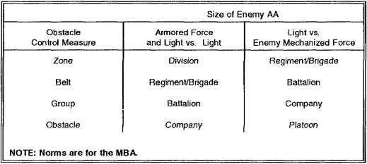
a. Obstacle Intent. The maneuver commander and his engineer designate an obstacle intent in order to focus the entire force. Obstacle intent describes how, in terms of obstacle effects, the commander will use tactical obstacles to effect the enemy's maneuver to the advantage of his fire plan (indirect and direct). The obstacle intent integrates and synchronizes the obstacle and fire plans.
b. Obstacle Integration and Synchronization. Obstacle intent must contain three components in order to accomplish integration and synchronization--an obstacle effect, a defined target and a relative location on the battlefield.
The obstacle effect is conveyed through the use of precise graphics (see Figure 3-2). The maneuver commander and his staff must understand the flexibility of these graphics. Each symbol represents how the enemy's maneuver should be altered as a result of the particular obstacle. For example, a turn symbol points the desired direction for the enemy to follow. Figure 3-2 also shows examples of how obstacle belts alter an enemy's formation through the use of obstacle groups. (Obstacle zones, belts and groups will be discussed in paragraph c.)
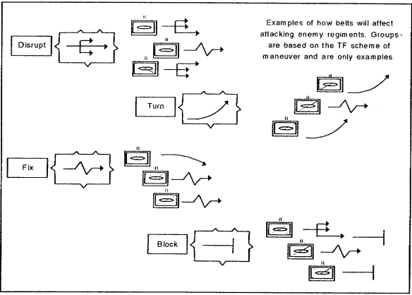
Figure 3-2. Obstacle effects and enemy formations/belts
A defined target refers to the enemy whose ability to maneuver is the target of the obstacle and fire plan. The target is relative to friendly unit allocation. For example, an armored maneuver brigade will fight an enemy division.
The relative location on the battlefield refers to the use of obstacle control measures. Figure 3-3 shows the relative locations for each planning and control echelon. Obstacle zones and belt use an enclosed, unspecified obstacle symbol. Obstacle groups use the obstacle effect symbol alone on the exact terrain where direct and indirect fires will be integrated and synchronized with individual obstacles.
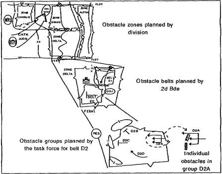
Figure 3-3. Obstacle control
c. Echelons of Obstacle Planning and Control-Measure Functions. In order to effectively plan and focus the obstacle effort the engineer must understand the employment of obstacle-control measures, zones, belts, and groups and individual obstacles. The corps and division engineer plan influences the obstacle planning process down to the obstacle-emplacing unit.
(1) Corps obstacle plan. Centralized control of denial activities normally begins at corps level. The corps obstacle plan is general in nature and covers the use of obstacles as part of a specific tactical operation. The obstacle plan supports the corps commanders concept of the operation and integrates the terrain aspects of the operation with the tactical plan. Through the allocation of engineer support and logistics, the corps commander shapes the division's countermobility efforts by weighting those areas viewed as most critical. The corps obstacle plan provides a framework for the division plan and normally includes the following items:
- Assignment of areas of responsibility.
- Designation of any specific obstacles vital to the corps as a whole.
- Completion times of portions of the obstacle plan when deemed necessary. However, completion times can be specified later.
- Gaps, lanes, and important routes to be kept open and areas important to the commander for tactical CSS operations and future operations. Gaps and lanes are specifically designated at the lowest level practicable, in consonance with the command's mission.
- Allocation of engineer support, materials, transportation, and equipment.
- Reporting instructions to ensure that all headquarters in the chain of command keep abreast of the obstacle situation and plan their operation accordingly.
- Coordination required between adjacent units to ensure that critical points (such as common boundaries) are effectively covered and that gaps and lanes are properly located, sufficient in number, and not closed for passage before the time required.
- Procedures for employing scatterable mines, to include provisions for air and artillery delivery, if not specified by standing operating procedure (SOP).
- Limitations or restrictions on employing certain reinforcing obstacles (such as minefields and booby traps) and chemical contamination. To guard against premature execution, restrictions may be placed on the employment of reinforcing obstacles. Subordinate units may be required to request approval for the closure of gaps and lanes.
- Limitations or restrictions on emplacing obstacles in a specific area. The corps may designate areas to remain obstacle-free, ensuring the corps commander freedom of maneuver for counterattacks and reinforcing movements.
- Limitations on and conditions for the destruction of facilities of strategic importance such as locks, dams, major bridges, and tunnels.
- Instructions regarding the submission of detailed obstacle plans for approval.
The corps obstacle plan is a C2 means for the corps commander to communicate the countermobility concept to subordinates. Corps obstacle plans must be provided to the Army battlefield coordination element (BCE), which is the land force's coordinating agency with the Air Force tactical air-control center (TACC). As the corps obstacle plan is modified or executed, continuous information will be provided by the corps to the BCE, which will have the information available for TACC planning. Known locations of enemy obstacles will be included. This coordinating and sharing of information is accomplished for several reasons:
- To assist United States Air Force (USAF) targeting efforts. Knowing the location of land-force emplaced obstacles will assist the Air Force in attacking concentrated enemy elements created by obstacle employment.
- To prevent duplication of effort by air and land forces.
- To assist with ground movement by USAF elements such as radar and logistics elements.
(2) Division obstacle plan. The corps plan is received at division level and analyzed for specified and implied tasks. The division obstacle plan is developed in two stages--an initial and a final plan.
(a) Initial plan. An initial plan (based on the corps obstacle plan, the division tactical plan, fire plans, maps, terrain analysis, and reconnaissance) is disseminated to the brigades and other subordinate units as quickly as possible. This allows time for obstacle selection on the ground. This must be done in conjunction with selecting fighting positions and locating weapon systems. The initial plan will include an overlay showing targets directed by corps or higher headquarters and obstacles of such importance as to be specified by division. The division plan includes the use of obstacle zones (see Figure 3-4) to control and focus the obstacle effort for subordinate units.
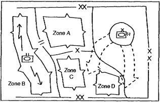
Figure 3-4. Division obstacle zones
Obstacle zones are planned to give maximum flexibility to maneuver brigades while preserving the freedom of the division maneuver force and reserves. The division engineer and the G3 use obstacle zones to limit or authorize where subordinate brigades can emplace tactical obstacles. Obstacle zones given to subordinate units do not cross their boundaries.
By not crossing the subordinate boundaries, obstacle zones enhance C2, assign specific responsibilities, and facilitate future operations. In addition, the plan will assign responsibilities and priorities as well as allocate obstacle materials, including scatterable mines.
By designating where tactical obstacle effort is authorized (zones), the division staff can initiate plans for transporting obstacle material from the corp ammunition transfer point to the forward brigades using a throughput system.
Obstacle intent is not normally assigned to obstacle zones. The intent will be given only when the division commander deems it a division-essential task having a specific effect on an attacking division. Turn and block are generally the only two obstacle effects associated with division-essential tasks. For the purpose of planning future operations, the division plan generally includes as much information from the corps plan as appropriate.
(b) Final plan. The detailed plans developed by the brigades and other separate subordinate units are incorporated with the initial plan to produce the final plan. The final obstacle plan will normally be issued as an annex to the division operations order (OPORD). When time is extremely limited, the division plan may never be developed beyond the initial plan. Conversely, when adequate time is available, the division plan will be submitted to corps and may be incorporated into a republished corps obstacle plan. The complete division obstacle plan should not be carried forward of division headquarters because of the danger of compromise. Division headquarters should provide each brigade with extracts of the detailed plan, to include pertinent portions from the plans of adjacent brigades.
(3) Brigade obstacle plan. Brigades and comparable units develop a detailed obstacle plan within the guidance provided by division. This plan is based on their tactical plans and detailed terrain reconnaissance. Brigade obstacle plans mirror the division obstacle plan outline. If combat is imminent, the preparation of obstacles begins immediately without waiting for approval of the obstacle plan. Obstacle construction and obstacle plan development continue concurrently. Brigade obstacle plans include the following:
- The location and type of each obstacle, including those specified by higher headquarters.
- A timetable and priority of construction for obstacles.
- Specific orders stating under what conditions and by whose authority reserve obstacles are to be executed.
- Routes to be kept open according to the tactical and logistical plan, including those specified by higher headquarters.
- The exact location and extent of gaps and lanes, including those specified by higher headquarters.
Brigades plan the use of obstacle belts within the division's planned obstacle zones (see Figure 3-5). The obstacle belt intent specifies to the TF commanders what effect the scheme of maneuver and the obstacle must have on the enemy' ability to maneuver.
The brigade commander designates obstacle belts to his subordinate maneuver battalions (based on the division's obstacle zones) to support the brigade's scheme of maneuver. Obstacle belts focus and synchronize the brigade's obstacle effort, particularly between adjacent TFs. Obstacle belts do not cross maneuver battalion boundaries for the same reasons that obstacle zones do not cross brigade boundaries.
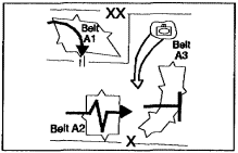
Figure 3-5. Brigade obstacle belts
Obstacle belts generally straddle the enemy's AA that the maneuver battalions are allocated against. Tactical obstacles are only permitted within the confines of the obstacle belt graphic. This is the first level of obstacle planning where an obstacle intent must be given for each obstacle belt. The intent describes to the TF commanders the intended effects of obstacles within a belt. An example of an obstacle belt intent would be, ..."The intent of obstacle belt A2 is to turn a motorized rifle regiment (MRR) on AA 2 and place the MRR in EA Skull."
Since brigades allocate maneuver companies based on MRB mobility corridors and task-organize TFs to defeat MRRs, obstacle belts and their effects are directed against MRR mobility corridors.
The belt graphic and intent also facilitate throughput of Class IV and V (obstacle) supplies to the maneuver battalions. The brigade engineer resources obstacle belts based on the belt intent the standard planning factors, and the sum of the mobility corridors that the belt straddles. This provides an approximation of the linear obstacle effort needed to achieve the belt intent.
Multiplying the sum width of all mobility corridors by the planning factor (shown in Table 3-2) gives the amount (in km) of linear obstacle the TF needs to accomplish the mission.
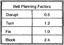
Figure 3-6 shows an example of a brigade's resourcing plan. Note that in belt A3 there are two mobility corridors that give a sum of 3.6 km. The intent of the belt is to block. Therefore, 3.6 km x 2.4 = 8.64 linear km of obstacle required.
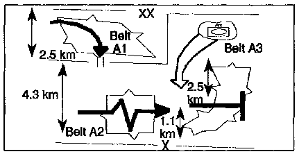
Figure 3-6. Brigade obstacle belts
(4) TF obstacle plan. To be effective, brigade obstacle plans must be integrated at the maneuver-unit level. Obstacle integration means establishing a clear link between obstacle effect and the direct-/indirect-fire plan. It ensures that the obstacle plan, the organization of the EA, and force allocation are mutually supporting.
TFs use obstacle groups as the basis for their obstacle planning. Obstacle group symbols show how obstacles will integrate with fires and maneuver. Obstacle groups are used by the commander to focus indirect and direct fires and individual obstacle effort. The TF commander designates groups rather than targets because the location of individual targets hinges on sitings at the company team level. The direct-fire plans are designed based on the maneuver of MRBs and independent motorized rifle companies (MRCs). TFs allocate platoons against MRC mobility corridors and task-organize them into company teams to defeat MRBs. Therefore, obstacle groups are generally used to attack the maneuver of MRB-sized forces.
Obstacle groups directly target the threat formation that the maneuver company teams are allocated against. Groups combine individual obstacles to accomplish a single effect, much the same as an artillery combines fires to create a specific effect. Obstacle group effects have specific integration techniques with the direct- and indirect-fire organization of the EA.
The TF commander allocates groups based on the obstacle belt intent and graphics along with the TF's scheme of maneuver. The summation of the obstacle groups that the TF directs must accomplish the obstacle intent. In other words, if the TF is given the responsibility for a turning obstacle belt, the TF commander is not limited to turning groups only. For example, the TF commander could target a first-echelon enemy battalion with a disrupting obstacle group, followed by a blocking obstacle group that denies a specific mobility corridor, and ending with a turning obstacle group against other enemy battalions. The total effect of the obstacle groups is turning an attacking enemy regiment (see Figure 3-7). The group effect or obstacle intent drives obstacle siting and is important to convey to commanders.
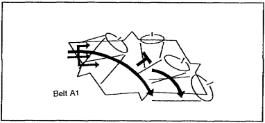
Figure 3-7. TF obstacle groups within a brigade obstacle belt
PART B: THE OBSTACLE PLANNING PROCESS
3-4. Obstacle Planning Steps. TF obstacle planning is a part of the decision-making process. This part of the lesson focuses on how to plan obstacles at the TF level. Table 3-3 outlines the steps needed in planning obstacles. They are described in sequence but are not meant to be treated as a lock-step routine. Several of the steps may be conducted concurrently. It is, however, a good framework to use when planning obstacles at the TF level.
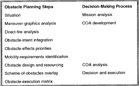
3-5. Mission Analysis. The main step of the mission analysis is to determine the situation template (SITEMP). The SITEMP shows the AAs and mobility corridors available to the enemy. The engineer must understand how the Intelligence Officer (US Army) (S2) believes the enemy will plan his attack. Understanding the enemy's maneuver is essential to planning obstacles that attack his maneuver.
3-6. Detailed Planning. After the staff develops a COA, detailed obstacle planning begins. The staff focuses on maneuver, direct- and indirect-fire analysis, and obstacle integration.
a. Maneuver-Graphics Analysis. The engineer must understand the maneuver plan if he is to effectively integrate obstacles to support that plan. Often, the maneuver graphic is developed without overlaying the SITEMP. This can lead to disaster. The overlaying process reveals how the commander plans to use his forces against the enemy's probable plan of attack and forms the basis for the rest of the obstacle planning process. Figure 3-8, shows a maneuver graphic for a typical TF area. Figure 3-9, shows the maneuver graphic with an overlaid SITEMP.
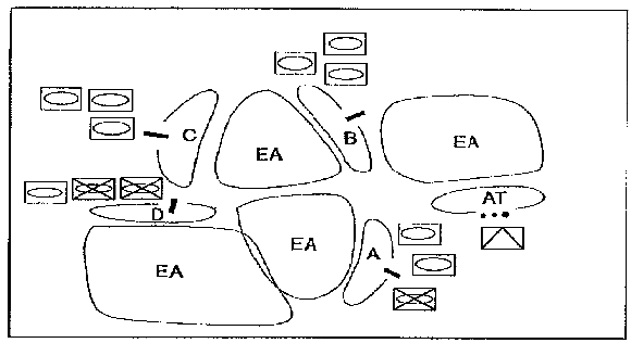
Figure 3-8. Maneuver graphic
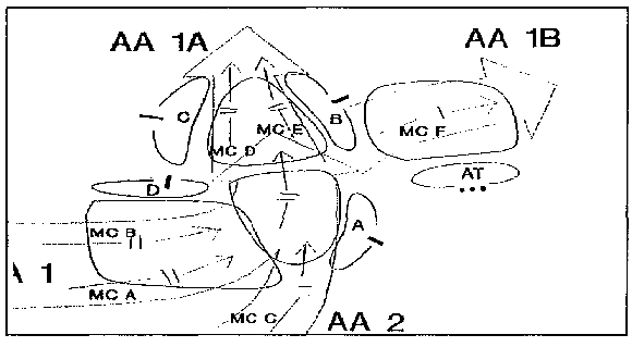
Figure 3-9. SITEMP/maneuver analysis
b. Fires Analysis. Knowing the possible enemy maneuvers and friendly defensive plan, the engineer and commander look at the organization of fires through a direct-fire analysis (see Figure 3-10). They consider areas where fires should be massed and shifted. A good technique is to draw the engagement ranges of each weapon and highlight the direct-fire control measures used to orient mass, and shift these fires. This step ensures that engineers do not place obstacles outside the range of friendly direct fires. War-game the TF execution matrix and enemy maneuver to get a feel for how the EAs are organized and how direct and indirect fires should shift as the battle progresses. The following are areas of consideration for direct-fire analysis:
- Areas of massed fires.
- Task organization.
- Weapons effects.
- Direct-fire control measures.
- Direct and indirect-fire organization of EAs.
- - Execution matrix.
- Target reference points (TRPs).
- Trigger lanes.
- Shifting fires.
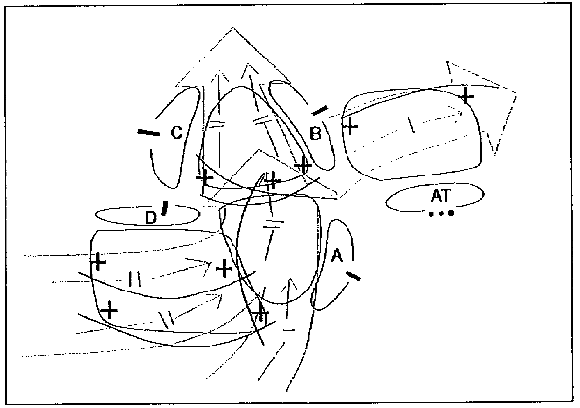
Figure 3-10. Direct-fire analysis
c. Obstacle-Intent Integration. Now the planners establish an obstacle intent. In short, the staff determines locations for directed obstacle groups. Planners consider the anticipated enemy attack look at the direct-fire plan, then decide where and what obstacle effects can be used to support the obstacle plan. The obstacle-intent graphics (see Figure 3-11) represent where a group of obstacles will be emplaced to affect the desired intent on the enemy. As a rule, these obstacle groups are allocated against MRB and independent MRC mobility corridors. This keeps their integration with the fires of a single company team aligned and simplifies integration and siting at the company team level.
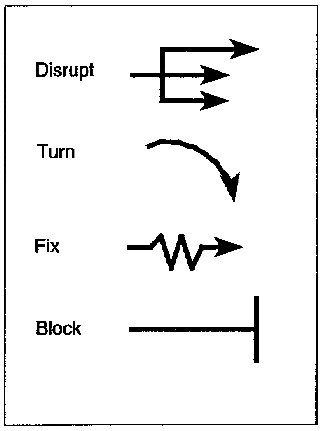
Figure 3-11. Obstacle intent effects
As planners decide what type of obstacles to use (disrupt, turn, fix, and block), they keep in mind the type of weapons covering them to ensure compatibility. For instance, a platoon of TOW missiles may not have sufficient volume of lethal fire to anchor a turning obstacle. Also, they identify the need for additional direct-fire control measures. There may be a TRP designated at the turning obstacle's turning point, but no control measure that shifts those fires with the turn.
Figures 3-12 and 3-13 show how obstacle groups support the overall intent of obstacle belts directed by the brigade. The groups attack MRBs and separate MRCs based on the direct-fire plan, while the belts are directed against MRRs.
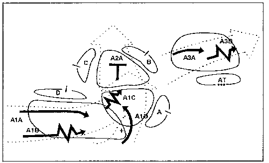
Figure 3-12. Obstacle-intent integration
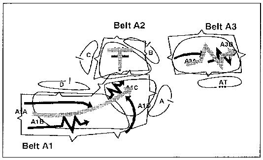
Figure 3-13. Obstacle-intent integration
d. Obstacle-Effects Priorities. With obstacle groups established, the commander needs to establish obstacle priorities (see Figure 3-14). The commander, the S3, and the engineer develop priorities on which obstacle effects (groups) are most important to the scheme of maneuver. The engineer manages his resources based on the commander's priorities. The number one priority obstacle group does not necessarily have to be emplaced first. Often, the commander may want to emplace the priority obstacle group during limited visibility, or the engineer may want to emplace obstacle groups forward of the priority group first. The engineer must not allow the resources (time, material, equipment, and manpower) to fall below that needed to emplace the group. The commander may also designate priorities for protective obstacle effort. This allows the engineer to assist the TF in allocating the materials needed for maneuver units to emplace protective obstacles.
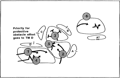
Figure 3-14. Assigned obstacle-effects priorities
3-7. COA Analysis. The staff war-games to determine which COA they should recommend. After war gaming the staff may adjust the obstacle group's location and effect and add situational or reserve obstacles. They will also identify mobility requirements and design and resource obstacles.
a. Mobility Requirements Identification. Planners now identify mobility requirements for emplacing lanes through obstacles (see Figure 3-15). Often, a TF will plan obstacles around their mobility requirements rather than the enemy's maneuver. In other words, the engineer does not plan for obstacles on the main supply route (MSR) because he does not want the problems associated with lane control and the risk of fratricide (friendly casualties by friendly fires). This is the wrong logic. Plan obstacles to attack the enemy's maneuver in a way that supports the maneuver plan. If you need lanes, then construct lanes and plan for their C2. The following are considerations for identifying mobility requirements:
- Tactical repositioning.
- TF sustainment traffic.
- C2 traffic.
- EA rehearsals.
- - Counterreconnaissance force or scouts.
- Counterattack force.
- Reserves.
- - Major supply route.
- Company team logistical packages (LOGPACs).
- Medical evaluation.
- Obstacle material resupply.
- - Leader reconnaissances.
- Face-to-face coordination at C2 centers.
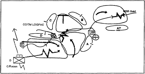
Figure 3-15. Mobility requirements identification
The engineer coordinates with the TF's S3 and commander to ensure that he has identified and planned for all mobility requirements resulting from tactical repositioning. The engineer coordinates with the TF's executive officer (XO) to ensure that he has identified and planned for mobility and sustainment operations. The lane requirements to support sustainment operations are the hardest to plan because they involve so many other staff officers and units. They are also the hardest to command and control.
b. Obstacle Design and Resourcing. The commander can now design the obstacles. Obstacle design begins by resourcing the groups based on mobility corridor widths and the desired effect. Once the obstacle groups are resourced, the engineer designs the individual obstacles using the intent graphics as a guide. The design of individual obstacles may be conducted at the engineer platoon level if there has not been sufficient reconnaissance to lock in the direct-fire and obstacle plans. In short, platoon leaders may be given the obstacle groups, allocated the resources needed, and then required to design the individual obstacles based on the ground reconnaissance and coordination with company team commanders. Figure 3-16 shows a sample computation of linear meters of obstacle required to support the maneuver plan.
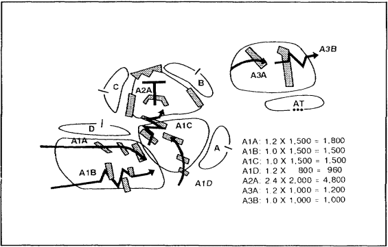
Figure 3-16. Obstacle design and resourcing
3-8. Decision and Execution. Once the commander selects a COA, the staff completes the plan and publishes the order. The TF provides obstacle details to the company team using the scheme-of-obstacles overlay and the execution matrix.
a. Scheme-of-Obstacles Overlay. The scheme-of-obstacles overlay (see Figure 3-17) is the final and most important product of the obstacle planning process. It shows commanders at the company team level where obstacle groups will be located on the battlefield and how the higher commander plans to use these obstacles to affect the enemy's maneuver. Most importantly, the obstacle intent graphically gives the commanders a tool that shows the link between the obstacle groups and intent and the direct-fire plans. When the commander overlays the obstacle group graphics on top of his operation overlay, he can immediately see how the obstacles will support his direct-fire plan and how the siting of TRPs is linked to siting the obstacles. Therefore, the overlay must show the obstacle groups using the intent graphics. If there has been sufficient reconnaissance and time for the TF engineer to design individual obstacles, they too may be shown on the scheme-of-obstacles overlay with the intent graphics. Lane locations or the need for lanes through obstacle groups is also shown, as well as closure responsibility. This lets the company team commander know where lanes must be emplaced in his AO. Finally, the scheme-of-obstacles overlay may indicate specific siting instructions needed to accomplish the commander's intent. For instance, the commander may be directed to site a turning obstacle in such a manner that the enemy is turned into TOW missile standoff range.
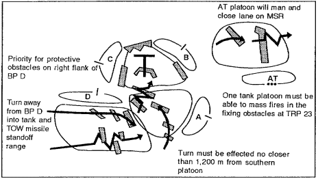
Figure 3-17. Scheme-of-obstacle overlay
b. Obstacle-Execution Matrix. The obstacle-execution matrix provides specific instructions and detailed information concerning the obstacles on the scheme-of-obstacles overlay. The matrix will cover the following headings: group No, location, priority, effect, emplacing unit, owning unit, and resource allocation (mines).
3-9. Obstacle-Group Synchronization. It is important to look at how obstacle groups are integrated into a fire plan at the company team level by the engineer platoon leader. As a general rule, a single obstacle group is covered by a single company team. It streamlines the obstacle group siting and emplacement processes if each group is assigned as a single platoon's mission. One engineer platoon leader is in charge of the group and integrates it into the company team's fire plan. This also reduces the number of engineers that the company team commander must coordinate with. In instances where more than one platoon is required, it must be clear which platoon leader is in charge. Synchronizing adjacent obstacle groups to ensure that they are mutually supportive is the TF engineer's responsibility. The following are considerations for obstacle group synchronization:
- Where possible, make obstacle groups a single platoon mission.
- If more than one engineer platoon is required, one platoon leader is in charge of the group.
- Mutual support between adjacent groups and EAs is the TF engineer's responsibility.
- Conflicts are resolved by the TF engineer, S3, and commander.
- - Normally one group per company team.
- The engineer platoon leader integrates the group into the company team fire plan and team engineer concept.
- - The group officer in charge (OIC) designs the obstacles.
- The group OIC ensures integration with company team commanders.
3-10. Coordination with Company Team Commanders. Successful, effective coordination between the engineer platoon leader and the company team commander is the most critical step in obstacle integration. Coordination begins with the engineer and the company team commander reviewing the AAs and mobility corridors in the company team's AO. The company team commander then identifies his direct-fire plan and tactical responsibilities for the engineer platoon leader and points out the location of his TRPs and EAs. The engineer verifies the company team's task organization and location of key weapons. Based on the scheme-of-obstacles overlay, the engineer platoon sites in the obstacle's intent. As they drive the obstacle intent, the commander and engineer platoon leader verify the group location, its intent, and its integration with the direct-fire plan. As the platoon drives the intent, they drop off markers that will be used later for individual obstacle siting. Coordination with company team commanders includes the following:
- Reviewing AAs and mobility corridors (mounted and dismounted).
- Identifying EAs and TRPs and understanding the company team direct-fire plan.
- Knowing the task organization (weapons available).
- Siting the obstacle intent (not each obstacle) based on the direct-fire plan.
- Monitoring weapons positioning and looking for mutual support with the obstacle intent.
- Verifying obstacle-group siting with the commander.
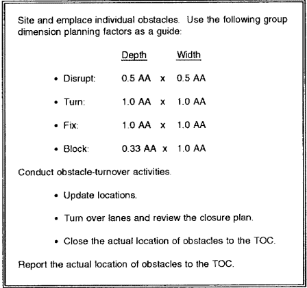
On occasion, the engineer platoon leader may fail to design the obstacles in sufficient depth or width to accomplish the intended effect. If this occurs, the emplacing engineer should use the group dimension planning factors as shown in Table 3-4. These factors are multiplied by the width of the mobility corridor to give the depth and width of the group. Individual obstacles are then sited and emplaced to give the group the necessary depth and width. Once the obstacles are emplaced, the platoon leader conducts obstacle turnover with the company team commander covering the obstacle. Finally, the engineer updates the TF engineer's tactical operations center (TOC) with the actual obstacle locations.
3-11. Obstacle Design. An important aspect of obstacle integration is ensuring that the individual obstacle is designed to meet the intent. This is true of minefields since parameters such as density, type of mine, frontage, depth, and the presence of antihandling devices must be determined. Figures 3-18 through 3-21, show a system of minefields that accomplishes specific intents. The row dimensions and mine spacing are shown. The AT pressure mines are surface-laid and the AT tilt mines are buried. Variations of the base minefield will be used in turning, fixing and blocking groups.
a. Minefield Intent: Disrupt. The disrupting minefield (see Figure 3-18) is essentially the base minefield. Shown in the upper left of the figure is the minefield characteristics. In the upper right is an illustration of the group showing the dimensions and intent. At the bottom center is the minefield pattern. Each disrupting minefield has a 2,500-meter front. Three of these minefields are usually needed to disrupt an MRB.
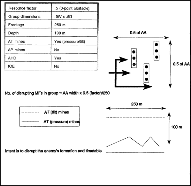
Figure 3-18. Minefield intent: disrupt
b. Minefield Intent: Turn. The turning minefield (see Figure 3-19) uses two base minefields. The minefield on the enemy side consists of all tilt-rod AT mines. This brings the probability of kill up to the required 75 percent. The minefield has 500 meters of frontage so that each minefield directly affects an entire MRC at a time.
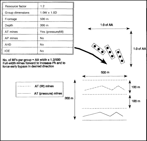
Figure 3-19. Minefield intent: turn
c. Minefield Intent: Fix The fixing minefield (see Figure 3-20) consists of the base minefield with an addition of an irregular outer edge (IOE) made up of tilt-rod AT mines. The IOE includes additional mines placed in an irregular pattern on the outer edge of the base minefields. The minefield frontage is 250 meters. This allows several minefields to be used throughout the depth of the fixing group so that there is sufficient frontage to cause several MRCs to breach repeatedly rather than bypass.
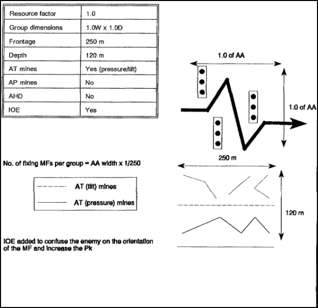
Figure 3-20. Minefield intent: fix.
d. Minefield Intent: Block. The blocking minefield (see Figure 3-21) gives maximum probability of kill, defeats dismounted and mounted breaching attempts, and confuses the enemy as to the minefield limits. It uses the base minefield with the IOE reinforced on the friendly side with an additional "all AT tilt-rod" base minefield. The minefield frontage is 500 meters.
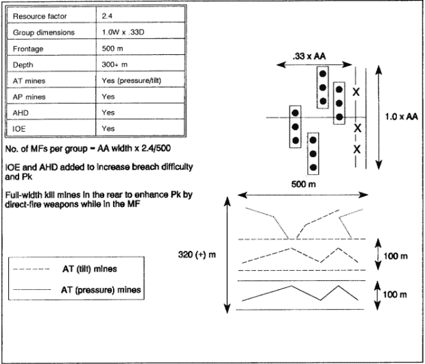
Figure 3-21. Minefield intent: block
3-12. Survivability Planning. Engineers make survivability recommendations using the obstacle intent. Survivability planning begins by receiving the commanders guidance for survivability. The commander usually gives his survivability intent in terms of the number and type of positions he wants for various weapons systems and battle positions. The commander may give guidance on which weapons have the priority for being dug in (such as infantry fighting vehicles, then tanks) and the type of position (turret or hull-down) that he wants dug for each weapon system. He may also indicate which units or battle positions have the highest priority. Finally, he tells his engineer whether he wants primary, alternate, or supplementary positions or any combination of the three. Based on this guidance, the engineer determines the number of positions, by type, needed to meet the commander's intent. Survivability planning capabilities are determined based on the following:
- Time available (days).
- Blade teams available.
- Work rates (1 hull/1 blade-team hour (BTH)), 1/turret/2.5 BTH, 70-meter antitank ditch (ATD)/1BTH.
- Travel factor 20 percent (1.2).
- 18 hours work/day.
Using the planning factors and formulas shown in Table 3-5, the engineer determines the number of hull or turret positions he can dig and the maximum amount of AT ditch he can dig.

3-13. Summary. This lesson addressed engineer obstacle and survivability planning, to include how to develop an obstacle plan and make recommendations to the maneuver commander at brigade, TF, and company levels. The primary focus was on obstacle intent, direct- and indirect-fire analysis, obstacle synchronization, and the integration of survivability effort into the obstacle plan.
Developing an obstacle plan that is effective and supports the tactical plan requires coordinated sequential planning. The following steps should be used to develop such an obstacle plan. These steps works for both offensive and defensive operations.
- Situation/maneuver-graphics analysis.
- Direct-fire analysis.
- Obstacle-intent integration.
- Obstacle-effects priorities.
- Obstacle design and resourcing.
- Mobility-requirements identification.
- Scheme-of-obstacles overlay.
The steps are described in sequence but are not meant to be treated as a lock-step routine. Several of the steps may be conducted concurrently. It is, however, a good framework to use when planning obstacles at the TF level.
Practice Exercise

