LESSON 6
| LESSON 6 | Lycoming T55. |
| TEXT ASSIGNMENT | Reference Text AL0993, paragraphs 5.1-5.22. |
| LESSON OBJECTIVE | To enable you to recognize and describe the Lycoming T55 gas turbine engine. |
| CREDIT HOURS | 2 |
Chapter 5
LYCOMING T55
5.1. INTRODUCTION
This chapter covers the Lycoming T55 gas turbine engine. Section I gives an operational description of the T55, covering the engine's five sections. Section II covers in detail each of the engine's sections and major systems.
Basically, all models of the T55 are of the same design. The major difference between the T5 5-L-7C and L-11 engines is that the L-11 has a two-stage gas producer turbine and the L-7C uses a single-stage gas producer turbine. However, the description and information given in this chapter are applicable to all models of the T55 except where noted. The Lycoming T55 engine is used to power the CH-47 Chinook helicopter.
Section I. Operational Description of the T55 Gas Turbine Engine.
5.2. GENERAL
This section describes in detail the inlet, compressor, diffuser, combustion, and power turbine sections, and the differences between models and specifications are compared.
Except for the discussion comparing models and specifications, the section's coverage is limited to the T55-L-7C and -11A engines.
5.3. DESCRIPTION
The T55 gas turbine engine is a direct-drive, annular reverse flow, free-power turboshaft engine developed for use in rotary-wing aircraft. An exploded view of the T55-L-11 A engine is shown in figure 5.1.
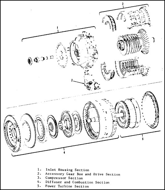
Figure 5.1. Exploded View of T55-L-11 A Engine.
The engine consists of an air inlet, accessory drive, compressor, diffuser, combustion, and power turbine sections. All the sections, except the accessory drive, form an annular (circular) flow path for air and hot gases. in addition, all the sections are structurally interdependent. The T55 is a direct drive engine, meaning it has no gear reduction, and the power output shaft speed is the same as the power turbine speed. The airflow paths through the T55-L-7 and L-11 A engines are shown in figures 5.2 and 5.3 respectively.
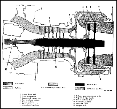
Figure 5.2. Engine T55-L-7 Series.
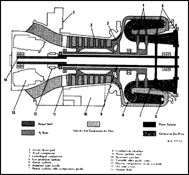
Figure 5.3. Engine T55-L-11 Series.
At the front of the engine, the inlet housing forms an annular airflow path to the inlet guide vanes (IGV) which are variable on the T55-L-11 A engine.
An airflow path is between the inner diameter of the housing and the base contours of the compressor stages. The compressor rotor has seven axial and one centrifugal stage compressor. The diffuser channel contains radial vanes which straighten the airflow from the centrifugal compressor. These vanes increase the static air pressure to its highest pressure at the diffuser exit. Air passes into the combustor section where its flow direction is changed twice. Flowing rearward from the diffuser, the air surrounds and enters the combustor liner through holes and louvers, and 28 swirl cups reverse the airflow direction for the first time. Each swirl cup contains a dual-orifice, fuel-atomizing nozzle. As combustion occurs, the hot expanding gases move forward to the curl assembly, again reversing the flow. The T55-L-7 uses 14 "T" cane vaporizer tubes to inject the fuel for combustion.
The gas flow is directed by the first and second stage nozzles to the two-stage gas-producer (GP) turbine. The T55-L-7C engines use a single-stage GP turbine. These turbines are attached to the rear of the compressor rotor shaft and extract the energy required to turn the compressor.
From the second stage turbine of the L-11A engine, the gas flow continues through the power turbine (PT) section. Most of the remaining energy of the hot gases is extracted by the two-stage PT and is transmitted by the power shaft to the power output shaft. After the expanding gases have passed through the PT section they are exhausted to the atmosphere through the exhaust duct.
The T55 series gas turbine engines are used to power the CH-47 Chinook helicopter. The CH-47B is powered by either the Lycoming T55-L-7, -7B, or -7C turboshaft engines. The CH-47C is powered by either T55-L-7C or T55-L-11 engines.
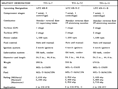
Basically, the Lycoming T55 series engines are of the same design and differ only in shaft horsepower and internal details. The T55-L-7 and -7B engines are rated at 2,200 shp at normal power and 2,650 at military power. The T55-L-7C engine is rated at 2,400 shp at normal power, 2,650 at military power, and 2,850 at maximum power. The T55-L-11 engine is rated at 3,000 shp at normal power, 3,400 at military power, and 3,750 at maximum power.
The T55-L-7C engine differs from the other T55-L-7 series engines in the following ways: (1) an atomizing combustor is used as opposed to the vaporizing type; (2) the 14 vaporizer "T" canes are replaced by 28 dual-orifice fuel spray nozzles for injecting fuel into the combustor; (3) four ignitors and start fuel nozzles are installed to ensure optimum ignition and flame propagation during starting. However, only two of the four start fuel nozzles are used; (4) a modified fuel control is used.
In addition, the T55-L-11 A differs from the T55-L-7 series in the following: (1)a two-stage gas producer(GP) turbine is used; (2) a more accurate electric torquemeter with an indicator reading in percent of maximum torque; (3) five thermocouple probes, that measure the gas temperature at the power turbine inlet; and (4) variable inlet guide vanes to improve compressor efficiency.
5.5. SPECIFICATION SUMMARY
Specifications for the T55-L-7, -7C and -11 engines used in Army aircraft are summarized in the following chart.
5.6. DIRECTIONAL REFERENCES AND ENGINE STATIONS
The diagrams in figure 5.4 and 5.5 show directional references and engine stations. Right and left sides of the engine are determined by viewing the engine from the rear. Direction of rotation of the compressor rotor and gas producer turbines is counterclockwise as viewed from the rear of the engine. The power turbine and the output gearshaft rotate in a clockwise direction.
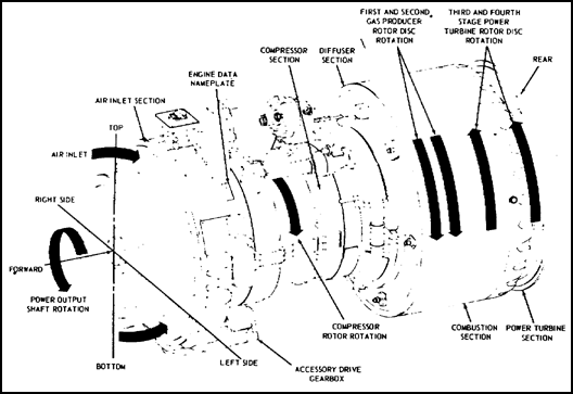
Figure 5.4. T55 Engine Directional References.
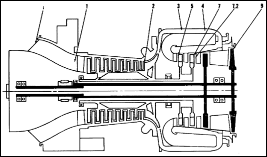
Figure 5.5. T55-L-11 Engine Stations.
Engine stations for the T55-L-11 A are shown in figure 5.5. The compressor housing is station No. 1 starting from the inlet guide vanes and extending to the centrifugal compressor. Station No. 2 starts at the beginning of the centrifugal compressor and ends at the air diffuser. Station No. 3 is from the air diffuser exit to the combustor inlet. Station No. 4 runs from the combustor inlet to the gas producer (GP) entrance. Station No. 5 is the GP entrance, station No. 7 is from the GP exit to the PT entrance. Station 7.2 is the PT entrance, and station No. 9 is the PT exit. No stations are shown for 6 and 8, because these numbers are not used.
5.7. SUMMARY
Basically, all models of the T55 series engine are of the same design and principle. The major difference between the L-7 and L-7C is that the L-7C uses 28 atomizing nozzles instead of the 14 vaporizing tubes in the L-7 engine. The T55-L-11 A differs from the T55-L-7C in that it has a two-stage GP turbine where the L-7C has a single-stage, and of course the shp is different for each model engine. The engine consists of an air inlet, accessory drive, compressor, diffuser, and combustion and power turbine sections. The T-55 series engine differs from engines we have previously covered in that it is a direct drive engine. The Lycoming T55 series engine is used to power the CH-47 Chinook helicopter.
Section II. Major Engine Sections and Systems
5.8. GENERAL
This section discusses the five major engine sections, beginning at the front: inlet, compressor, diffuser, combustion, and power turbine; then it continues with descriptions of various engine systems, including fuel, lubrication, and electrical systems. The text and illustrations cover the T55-L-11 A engine except where noted.
5.9. INLET SECTION
The air inlet housing is a one-piece magnesium alloy casting, with an inner and outer housing as shown in figure 5.6.
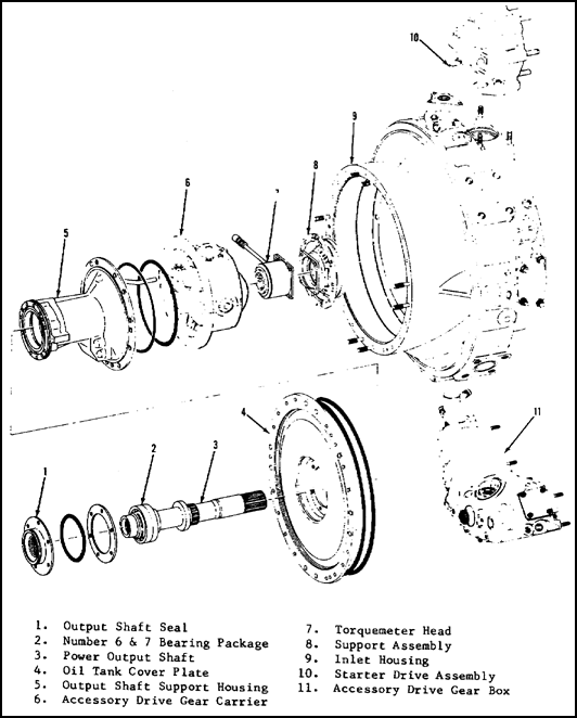
Figure 5.6. Inlet Housing Assembly.
Four engine mounting pads are on the inlet housing. The front face of the inner housing includes studs to mount the engine oil tank cover plate and a speed reduction gearbox. The inner housing, figure 5.6 item 9, contains the output shaft, the compressor rotor forward bearing support structure, the torquemeter head assembly, and a 3.75-gallon oil tank. The outer housing forms the outer wall for the annular inlet duct. Four struts make the structural connection between the two housings. The struts are hollow and have passages for oil and accessory drive shafts.
5.10. COMPRESSOR SECTION
The compressor rotor assembly, shown in figure 5.7, consists of a seven-stage, all-steel axial compressor and an all-titanium centrifugal compressor. The two compressors form a single rotating assembly providing an 8 to 1 compression ratio.
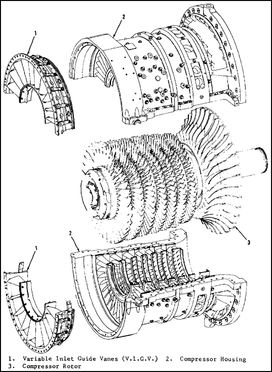
Figure 5.7. Compressor Section.
All axial compressor blades are stainless steel and mounted on steel compressor disks by dovetail roots and spring-loaded locking pins. Seven two-piece stator assemblies are bolted to a two-piece cast magnesium compressor housing, which encloses the axial and centrifugal rotors. The housing is split axially to permit complete access to the compressor rotor for inspection and blade replacement. The internal surfaces of these housings are coated with epoxy phenolic and graphite filler. The external surfaces are treated with epoxy phenolic gray paint.
On the L-11 engine, a variable inlet guide vane assembly is mounted in the front of the compressor housing. The axial compressor housing has an airbleed system consisting of a series of holes and machined passages. The system bleeds air from the sixth stage and thereby improves compressor performance. This system is controlled by an interstage airbleed system covered later in the chapter.
5.11. DIFFUSER SECTION
The air diffuser, shown in item 1 figure 5.8, is constructed of stainless steel. The diffuser receives high-velocity air from the centrifugal impeller. This radial airflow is changed to an axial flow by longitudinal guide. The divergent shape of the diffuser decreases velocity and increases air pressure. Air pressure at the diffuser discharge is at its highest value; air temperature is in the vicinity of 600° F. Temperature and pressure are directly related to rotational speed of the compressor. Internally, the diffuser supports the rear of the Compressor assembly through the No. 2 main bearing. Also mounted internally, but not a component of the diffuser, are the combustion chamber deflector curl, first and second stage GP nozzles, and turbine rotors.
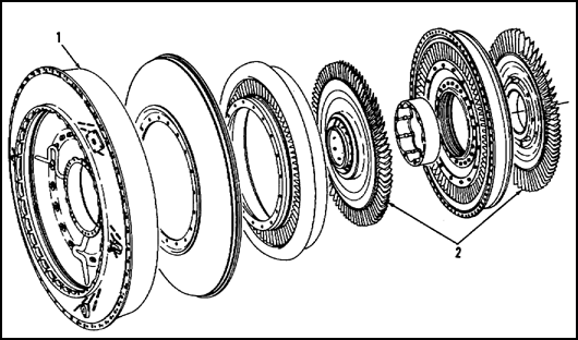
Figure 5.8. Diffuser and Gas Producer Turbine.
5.12. COMBUSTOR SECTION
The combustion chamber is a reverse-flow annular design, which permits maximum use of space and reduces gas producer and power turbine shaft length.
The atomizing combustor has 28 main fuel atomizing nozzles. The nozzles are of the dual-orifice design mounted in two interchangeable, dual-channel, main fuel manifolds, with 14 fuel nozzles in each manifold.
The perforated combustor liner, shown in figure 5.9, is manufactured from a heat-resistant alloy. The perforations are arranged to meter air into the combustor for combustion and cooling. Two combustor drain valves are located at the bottom of the chamber, to drain raw fuel on engine shutdown after a false or aborted start. Fuel is injected directly into the combustor through the atomizing nozzles which are mounted on the fuel manifold at the rear of the combustor.
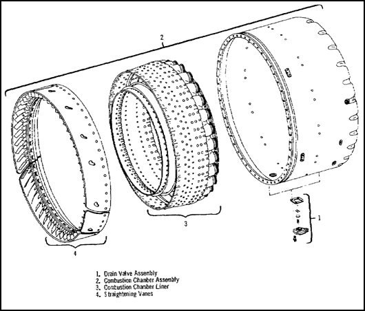
Figure 5.9. Combustion Chamber Housing Assembly.
5.13. TURBINE SECTION
The gas producer turbines on the T5 5-L-11 engine are two-stage, axial-flow turbines coupled together and mounted on the rear of the compressor rotor shaft. The gas producer turbine nozzles and rotors are shown in figure 5.10.
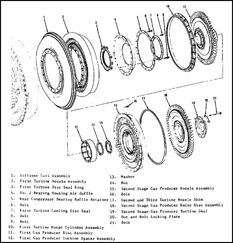
Figure 5.10. Gas Producer Assembly
The gas producer turbine blades are air-cooled hollow blades held in place on the disk by pins. Ahead of the first and second stage rotors are the gas producer nozzles, which direct the hot gas onto the turbine rotors. The power turbine assembly is shown in figure 5.11.
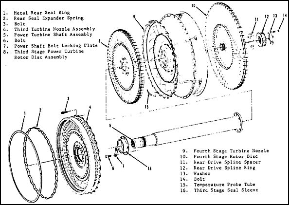
Figure 5.11. Power Turbine Assembly.
The power turbine is a two-stage, axial-flow turbine coupled together and mounted on the power turbine shaft. The power shaft transmits power from the power turbines to the power output shaft. Basically, the function of the power turbine is to extract velocity energy from the hot gases and deliver mechanical power to the output shaft. The GP and PT systems are mechanically independent of each other; however, their speeds are controlled by the fuel control unit.
5.14. DESCRIPTION OF FUEL SYSTEM
The fuel system of the T55- L-11 engine consists of the components illustrated in figure 5.12. The T55-L-7 engine uses 14 vaporizing tubes in place of the 28 dual atomizing nozzles on the L-7C and L-11 engine. A cross-section view of the flow divider and atomizing nozzles may be seen by referring to figure 4.21 and 4.23 in lesson 5. The following subparagraphs discuss the components in the fuel system.
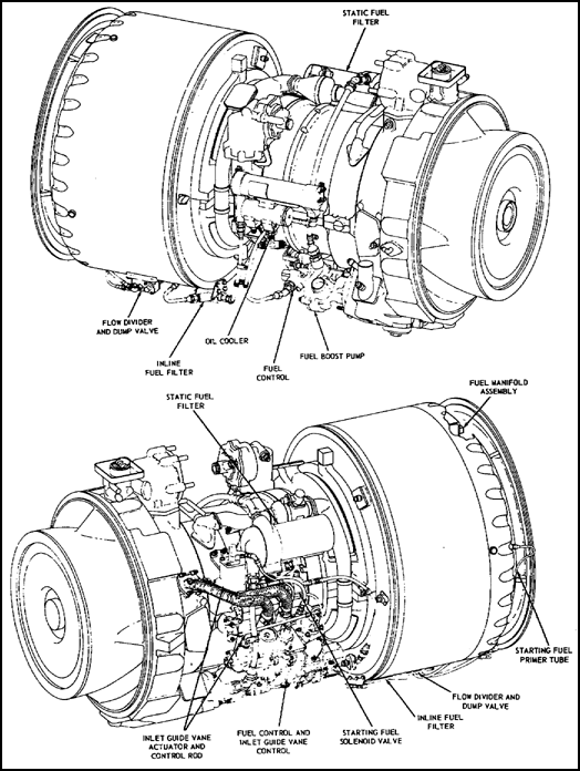
Figure 5.12. T55-L-11 A Fuel System.
![]() a. Fuel control. The hydromechanical fuel control contains a dual-element fuel pump, gas producer and power-turbine speed governors, an acceleration and deceleration control, an airbleed signal mechanism, and a fuel shutoff valve. Functionally, the fuel control unit can be divided into two sections: the flow control section and the computer section. A flow control schematic is shown in figure 5.13. The flow control section meters engine fuel flow. The computer section schedules the positioning of the metering valves in the flow control section. The computer section also signals the actuation of the compressor bleed band and the variable inlet vanes systems.
a. Fuel control. The hydromechanical fuel control contains a dual-element fuel pump, gas producer and power-turbine speed governors, an acceleration and deceleration control, an airbleed signal mechanism, and a fuel shutoff valve. Functionally, the fuel control unit can be divided into two sections: the flow control section and the computer section. A flow control schematic is shown in figure 5.13. The flow control section meters engine fuel flow. The computer section schedules the positioning of the metering valves in the flow control section. The computer section also signals the actuation of the compressor bleed band and the variable inlet vanes systems.
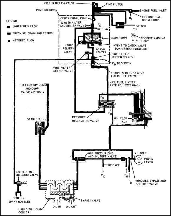
Figure 5.13. Fuel Control Flow Schematic.
![]() b. Liquid-to-liquid cooler. From the fuel control, fuel passes through the cooler mounted on the engine compressor housing. The cooler uses fuel to aid in cooling the engine oil. The cooler is a counter-flow type with the fuel passing through small aluminum tubes. The heat from the oil is transferred to the fuel. This type of cooler serves two purposes, to cool the oil and heat the fuel to aid in better atomization. A liquid-to-liquid cooler is illustrated in lesson 3, figure 2.12.
b. Liquid-to-liquid cooler. From the fuel control, fuel passes through the cooler mounted on the engine compressor housing. The cooler uses fuel to aid in cooling the engine oil. The cooler is a counter-flow type with the fuel passing through small aluminum tubes. The heat from the oil is transferred to the fuel. This type of cooler serves two purposes, to cool the oil and heat the fuel to aid in better atomization. A liquid-to-liquid cooler is illustrated in lesson 3, figure 2.12.
![]() c. Start fuel system. The electrically operated, normally closed igniter fuel solenoid valve is located on the compressor housing at the 9 o'clock position. The solenoid valve is actuated by a switch in the cockpit that energizes the valve and allows fuel to flow from the fuel control unit through the starting manifold and to the start fuel nozzles. On T55-L-5 and T55-L-7 engines, two start nozzles are connected to the starting fuel manifold at approximately the 3 and 9 o'clock positions. Starting fuel passes through these nozzles into the combustion chamber where it is ignited by a spark from an igniter plug adjacent to each start fuel nozzle. On T5 5-L-7C engines, four start fuel nozzles are connected to the starting fuel manifold at approximately the 1, 4, 7, and 10 o'clock positions.
c. Start fuel system. The electrically operated, normally closed igniter fuel solenoid valve is located on the compressor housing at the 9 o'clock position. The solenoid valve is actuated by a switch in the cockpit that energizes the valve and allows fuel to flow from the fuel control unit through the starting manifold and to the start fuel nozzles. On T55-L-5 and T55-L-7 engines, two start nozzles are connected to the starting fuel manifold at approximately the 3 and 9 o'clock positions. Starting fuel passes through these nozzles into the combustion chamber where it is ignited by a spark from an igniter plug adjacent to each start fuel nozzle. On T5 5-L-7C engines, four start fuel nozzles are connected to the starting fuel manifold at approximately the 1, 4, 7, and 10 o'clock positions.
![]() d. Main fuel system. The main and start fuel manifold are positioned on the rear surface of the combustion chamber assembly. The main fuel manifold consists of two manifold halves, with attaching points for 14 fuel vaporizer tubes. The main fuel manifolds for the T55-L-7 and L-7C/11A are shown in figure 5.14.
d. Main fuel system. The main and start fuel manifold are positioned on the rear surface of the combustion chamber assembly. The main fuel manifold consists of two manifold halves, with attaching points for 14 fuel vaporizer tubes. The main fuel manifolds for the T55-L-7 and L-7C/11A are shown in figure 5.14.
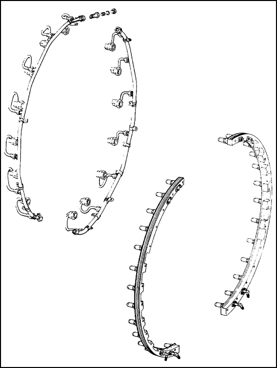
Figure 5.14. Main Fuel Manifolds.
The T55-L-7C and T55-L-11 engines have an improved fuel system. This system illustrated in figure 5.15 consists of 28 dual-orifice fuel nozzles in a two-section main fuel manifold. A flow divider was added to meter fuel to the fuel nozzles at 9 to 10 percent N1; as the rpm increases to 32 percent N1, secondary fuel flows to the nozzles.
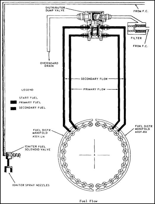
Figure 5.15. T55-L-11 Main and Start Fuel Flow.
5.15. INTERNAL COOLING AND PRESSURIZATION SYSTEM
The internal cooling system cools internal components and ensures extended engine service. A combination of several passages throughout the engine receives air from the main air-flow channel and directs it to cool components located within heat-generating areas. The exits from the cooling passages conduct the heated air to the main exhaust gas flow.
Some of the cooling air is extracted for bearing seal pressurization. This internal airflow is guided to the appropriate bearing seal to protect against oil seepage while the engine is in operation.
The engine inlet is protected from ice forming on it by the anti-icing system. The walls and struts of the inlet housing have internal passages through which hot, scavenged engine oil circulates. The variable inlet guide vanes are supplied with hot air which is extracted from the centrifugal compressor. The engine hot-air anti-icing system is shown in the schematic in figure 5.16.
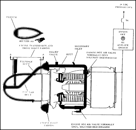
Figure 5.16. Hot-Air Anti-icing System.
This air first passes through a hot-air valve and is distributed by a tube which directs the air into an annulus (circular structure) around the inlet-guide vane assembly. The anti-icing air is routed through the stem of the vanes and is discharged at the base of the leading edge into the main airflow.
5.17. VARIABLE INLET GUIDE VANE SYSTEM
The inlet guide vane assembly, located in front of the first compressor rotor, consists of a series of hollow blades positioned mechanically by a hydraulically operated synchronizing ring. The guide vane control system schedules the positions of the variable inlet guide vanes in response to gas producer speed and compressor inlet temperature. At low N1 speeds, a high angle of inlet air is required, and the inlet guide vanes are in the closed position of approximately 45.5° of the engine centerline. Guide vane positions are illustrated in figure 5.17.
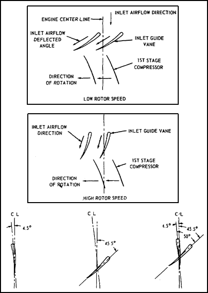
Figure 5.17. Angles of Variable Inlet Guide Vane.
When engine speed increases above 65 percent, the inlet guide vanes begin to open. The progression toward the open position is proportional to compressor speed. At 98 percent speed, the vanes are opened to 7° off the centerline, and as speed increases to 100 percent, the vanes cross the centerline to the -4.5° position. At any steady state N1 speed, between 65 percent and 98 percent, the inlet guide vanes assume a constant position.
5.18. INTERSTAGE AIR BLEED SYSTEM
An interstage air bleed actuator assembly and bleed band, illustrated in figure 4.27, are used to facilitate compressor rotor acceleration and avoid compressor stalls. A series of vent ports around the compressor housing, at the sixth stage of compression, permits compressor air to bleed off and allows a more rapid acceleration. The pneumatic interstage-actuator assembly controls operation of the air bleed system by tightening or loosening a metal band over the vent holes in the compressor housing. The bleed band and actuator assembly are shown in figure 5.18. The fuel control is equipped with an acceleration air bleed adjustment that sets the compressor rotor speed at which the interstage air bleed closes. This is usually factory set to close the bleed band at approximately 30 percent of normal rated power.
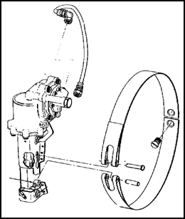
Figure 5.18. Interstage Airbleed Band Assembly.
5.19. LUBRICATION SYSTEM
The engine lubrication system has the dual function of lubricating and cooling. The principal components of the system are the integral oil tank, dual element lubrication pump, filter and screen assemblies, oil cooler assembly, oil level indicator assembly, and internal scavenge pumps. The entire lubrication system is self-contained within the engine. A 3.75-gallon oil tank is located in the engine air inlet housing. The tank filler neck is located at the top center of the inlet housing. Oil level indication is taken by means of an externally-mounted mechanical indicator. Two connections, one at the top and one at the bottom of the tank, are for the addition of an external oil tank to increase the oil capacity. The following subparagraphs discuss the lubrication system and components.
![]() a. Oil level indication system. The oil tank has an oil level indicator mounted on the left side of the inlet housing at the 9-o'clock position and can be read from the top or the side. The indicator contains a low-level warning switch for remote indication in the cockpit. Based on using the maximum allowable oil consumption rate, the switch is set to signal when there is a 2-hour supply of usable oil remaining.
a. Oil level indication system. The oil tank has an oil level indicator mounted on the left side of the inlet housing at the 9-o'clock position and can be read from the top or the side. The indicator contains a low-level warning switch for remote indication in the cockpit. Based on using the maximum allowable oil consumption rate, the switch is set to signal when there is a 2-hour supply of usable oil remaining.
![]() b. Oil flow. Oil from the tank flows from the bottom of the engine inlet housing through an external line to the pressure side of the main oil pump. The oil flow may be followed by referring to the schematic shown in figure 5.19.
b. Oil flow. Oil from the tank flows from the bottom of the engine inlet housing through an external line to the pressure side of the main oil pump. The oil flow may be followed by referring to the schematic shown in figure 5.19.
The main oil pump is located on the aft face of the accessory gearbox. It contains both pressure and scavenge elements. An adjustable relief valve in the pump maintains nearly constant oil pressure during engine operation. Oil goes from the pump and through a filter located in the accessory gearbox. A bypass valve will open if the filter becomes clogged. On the outlet side of the filter, oil temperature is measured by a temperature bulb. Then the oil is routed through the oil cooler into two external low paths. One flow path directs the oil to the rear of the engine. At that location it lubricates number 2, 4, and 5 bearings. The second flow path directs oil to the front bearings and accessory drive gear trains. Oil from the rear bearings is force-scavenged into an external oil-return line by paddle pumps mounted on the power turbine shaft. This scavenge oil is directed back to the accessory gearbox.
A scavenge impeller in the accessory gearbox picks up the scavenge oil and pumps it to the scavenge element of the main oil pump. The oil is then returned to the inlet housing where it is discharged into the oil tank.
![]() c. Chip detectors. On the T55-L-7, the engine magnetic chip detector is located in the scavenge-pump housing on the lower left face of the accessory gearbox. The detector attracts ferrous material, which builds up until it bridges a gap, as shown in the accompanying sketch. This makes it possible to check for the presence of foreign material by checking continuity across the contacts. The detectors are electrically connected to caution lights in the cockpit.
c. Chip detectors. On the T55-L-7, the engine magnetic chip detector is located in the scavenge-pump housing on the lower left face of the accessory gearbox. The detector attracts ferrous material, which builds up until it bridges a gap, as shown in the accompanying sketch. This makes it possible to check for the presence of foreign material by checking continuity across the contacts. The detectors are electrically connected to caution lights in the cockpit.
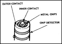
The T55-L-11 engine is equipped with three chip detectors. Each bearing scavenge line dual chip detector is mounted externally. Each detects ferrous and nonferrous metal chips originating in the No. 2, 4, and 5 bearing areas of the engine. Another is located near the gearbox scavenge impeller.
![]() d. Engine oil filters. The oil filter system consists of a main oil filter assembly and five secondary oil filters. Three of these filters are accessible for intermediate level maintenance. These are the No. 2 bearing strainer, located at the 3 o'clock position on the forward face of the diffuser housing assembly, and the No. 4 and 5 bearing strainers located in the supply tube within the exhaust diffuser. The main oil filter assembly, illustrated in figure 5.20, is mounted on the bottom of the accessory gearbox directly in front of the main oil pump, or fuel boost pump.
d. Engine oil filters. The oil filter system consists of a main oil filter assembly and five secondary oil filters. Three of these filters are accessible for intermediate level maintenance. These are the No. 2 bearing strainer, located at the 3 o'clock position on the forward face of the diffuser housing assembly, and the No. 4 and 5 bearing strainers located in the supply tube within the exhaust diffuser. The main oil filter assembly, illustrated in figure 5.20, is mounted on the bottom of the accessory gearbox directly in front of the main oil pump, or fuel boost pump.
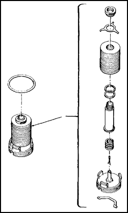
Figure 5.20. Main Oil Filter.
5.20. TORQUE METER SYSTEM
The Lycoming Electric Torquemeter used on the T55 engine is the same type that is used on the T53-L-701 covered in the previous chapter. To save describing the system in detail again, this paragraph is a brief review. When torque is imposed on the engine power output shaft, tension and compression stresses change the magnetic reluctance of the shaft. This change in magnetic reluctance is transmitted to an indicator in the cockpit and read as percent (%) of torque.
5.21. ELECTRICAL SYSTEM
The engine electrical system includes circuitry to facilitate starting, ignition, anti-icing, and all engine-oriented electrical monitoring devices. The following subparagraphs discuss the operation of the engine electrical system.
![]() a. Main electrical cable assembly. The main electrical cable assembly furnishes all necessary interconnecting wiring between the main disconnect plug and the nine-branch electrical connectors. The nine electrical accessories served by this cable are the gas producer tachometer generator, oil temperature bulb, fuel flow pressure switch, torquemeter system, ignition exciter, anti-icing solenoid valve, starting fuel solenoid valve, oil level indicator, and power turbine tachometer generator. The main disconnect plug mates with an electrical receptacle of the airframe wiring, establishing electrical continuity to the various airframe components.
a. Main electrical cable assembly. The main electrical cable assembly furnishes all necessary interconnecting wiring between the main disconnect plug and the nine-branch electrical connectors. The nine electrical accessories served by this cable are the gas producer tachometer generator, oil temperature bulb, fuel flow pressure switch, torquemeter system, ignition exciter, anti-icing solenoid valve, starting fuel solenoid valve, oil level indicator, and power turbine tachometer generator. The main disconnect plug mates with an electrical receptacle of the airframe wiring, establishing electrical continuity to the various airframe components.
![]() b. Ignition exciter. The high-potential ignition pulse is developed by the ignition exciter; 24 volts dc is applied to the input of the exciter. Current flows through the primary transformer winding the bias coil and the vibrator points to ground. This generates magnetic lines of force which permeate the transformer core and the core of the bias coil attracting the vibrator reed upward and interrupting the circuit. As current flow ceases, the lines of force collapse and the reed falls back, closing the circuit. This cycle repeats at a rate proportional to the input voltage. The resultant current flows in pulses, causing magnetic lines of force to build up and collapse with each pulsation. These lines induce voltage across the secondary coil which is transformed to a higher potential by an increased number of windings comprising the secondary. The diodes rectify the pulsating current back into direct current to charge the capacitors. The charge on the capacitors continues to build up at a rate proportional to input voltage, until a potential of 2,500 volts exists. The calibrated spark gaps ironize at this voltage, creating an electrical path for the firing pulse. The capacitors discharge through this path into the lead and coil assembly for distribution to each of the spark igniters.
b. Ignition exciter. The high-potential ignition pulse is developed by the ignition exciter; 24 volts dc is applied to the input of the exciter. Current flows through the primary transformer winding the bias coil and the vibrator points to ground. This generates magnetic lines of force which permeate the transformer core and the core of the bias coil attracting the vibrator reed upward and interrupting the circuit. As current flow ceases, the lines of force collapse and the reed falls back, closing the circuit. This cycle repeats at a rate proportional to the input voltage. The resultant current flows in pulses, causing magnetic lines of force to build up and collapse with each pulsation. These lines induce voltage across the secondary coil which is transformed to a higher potential by an increased number of windings comprising the secondary. The diodes rectify the pulsating current back into direct current to charge the capacitors. The charge on the capacitors continues to build up at a rate proportional to input voltage, until a potential of 2,500 volts exists. The calibrated spark gaps ironize at this voltage, creating an electrical path for the firing pulse. The capacitors discharge through this path into the lead and coil assembly for distribution to each of the spark igniters.
Radio frequency energy is generated within the exciter during normal operation. An inductive capacitive filter has been incorporated at the input to prevent this energy from being fed back into the 24-volt input line. Radio frequency interference on this line could be detrimental to the operation of other electrical accessories. This filter is tuned to radio frequencies and does not offer any appreciable opposition to the flow of 24-volt direct current.
![]() c. Ignition lead and coil assembly. The ignition lead and coil assembly constitutes the high-potential ignition wiring. This assembly incorporates two coils, fed with high voltage from the two outputs of the ignition exciter. The coil assemblies function as spark splitters distributing high voltage to four igniter plugs. Each coil assembly has one input and two outputs with the coil windings forming a transformer having a 1:1 ratio. Any current flowing through either winding will induce a voltage across the other so that even a shorted igniter plug will not short out the high-voltage ignition signal. The entire wiring harness is shielded and grounded at the airframe to suppress radio frequency interference.
c. Ignition lead and coil assembly. The ignition lead and coil assembly constitutes the high-potential ignition wiring. This assembly incorporates two coils, fed with high voltage from the two outputs of the ignition exciter. The coil assemblies function as spark splitters distributing high voltage to four igniter plugs. Each coil assembly has one input and two outputs with the coil windings forming a transformer having a 1:1 ratio. Any current flowing through either winding will induce a voltage across the other so that even a shorted igniter plug will not short out the high-voltage ignition signal. The entire wiring harness is shielded and grounded at the airframe to suppress radio frequency interference.
![]() d. Exhaust gas temperature harness. The chromel-alumel, thermoelectric measuring system is independent of all other engine electrical wiring. The engine components are ten thermocouple probes to the shielded harness. The aircraft wiring, spool resistor, and indicator complete the system. The ten thermocouple probes protrude into the gas flow of the engine at station number 7. The probes react to variations in power turbine entry temperature by developing a proportional electromotive force across the chromel-alumel junction. This electromotive force results in meter deflection of the cockpit indicator calibrated to read temperature in degrees centigrade.
d. Exhaust gas temperature harness. The chromel-alumel, thermoelectric measuring system is independent of all other engine electrical wiring. The engine components are ten thermocouple probes to the shielded harness. The aircraft wiring, spool resistor, and indicator complete the system. The ten thermocouple probes protrude into the gas flow of the engine at station number 7. The probes react to variations in power turbine entry temperature by developing a proportional electromotive force across the chromel-alumel junction. This electromotive force results in meter deflection of the cockpit indicator calibrated to read temperature in degrees centigrade.
5.22. SUMMARY
The T55 series gas turbine engine is used to power the CH-47 Chinook helicopter. The CH-47A and B are equipped with the T55-L-7 series engines, and the CH-47C is equipped with the T55-L-7C or T55-L-11 . These are all basically the same except for shaft horsepower ratings and internal details. The fuel system includes starting and main fuel components. The fuel control is a hydromechanical device that automatically meters the proper amount of fuel under varying atmospheric conditions and power requirements. The engine has its own lubrication system with the oil tank contained within the inlet housing. It is equipped with an interstage bleed air system to facilitate acceleration and avoid compressor stalls. The anti-icing system prevents icing by ducting hot air from the diffuser section to the engine inlet. The engine has a starting and ignition system, and its performance is monitored by instruments on the cockpit instrument panel.
GO TO:

