

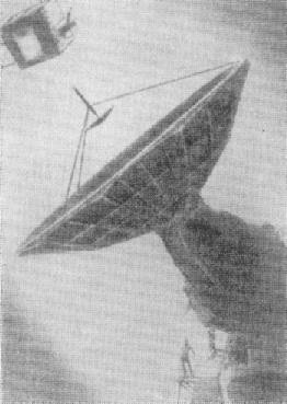
Hen Egg - Antenna RS-10 RNS RTS
GV Kisunko proposed to solve the problem of radar precision tracking and defeat of ballistic targets using the "three distance" triangulation method. To implement this method, three antennas (to support a ballistic target and an anti-missile) were needed, capable of simultaneously emitting narrow beams with very high impulse power in the shortwave part of the decimeter radio band. The RS-10 antennas with a diameter of 15 m were designed and implemented to support a ballistic target and a RS-11 with a diameter of 4.5 m to support an anti-missile with so-called (incorrectly) bilocular support-rotating devices. The antennas RS-10 and RE-10 had basically the same design.
Radar of precise guidance (chief designer - GV Kisun'ko). Precision sighting radar detected and accompanied the target according to external target designation data generated by the central computer station. According to the radar of precise guidance, the trajectory of the target was refined and pre-launch calculations were made. Precision-guided radars also received target designations for the anti-missile and accompanied it in range. At the stage of accurate guidance on three ranges to the target and three distances to the missile, measured by the radar of precise guidance, anti-missile control commands were developed, and at the end of the guidance, a command to undermine the combat unit. The error in determining the difference in range to the target and the interceptor at the stage of accurate aiming of the antimissile missile on the target did not exceed 10 m. The station had an automatic zero-range alignment scheme to the target and an interceptor on the control signal. The antenna paraboloid of the target channel had a diameter of about 15 m, which provided a sharply directed beam with a width of 0.7 deg to 0.7 deg. Through this antenna, the target was irradiated with high-frequency pulses and pulses reflected from the target were received. Weight of the moving part of the antenna device was 92 thousand kg. The drive devices had a power of 70 and 40 kW. ?????????: http://www.vko.ru/oruzhie/tochka-otscheta-v-istorii-pro The development was carried out on a broad front and at a rapid pace. During only one year in 1956, 30 models were designed and manufactured in SKB-30, including two models in the scale 1: 5 of the RS-10 antenna system. One of these models had a cast reflector, made with a tolerance of 0.5 mm. A waveguide measuring stand was developed and manufactured for a new range, as well as models of a four-way irradiator, rotating articulations and other nodes of waveguide paths.
Three RS-10 and RS-11 antennas were installed on three precise aiming radars (RNS) at the 1st, 2nd and 3rd sites of the test site. Radar guidance Precise (PST) / objects 1, 2 and 3 - according to the target designation of the radar radar, three precision targeting radars PEN / HEN EGG (RTN- 1, RTN-2 and RTN-3) were included. The RTN radar is a radar with a full-rotating relector antenna with mechanical rotation, providing support for a ballistic target missile and anti-missile. NIIRP is developer of The, the chief designer is the GV Kisun'ko, The co-developer is ALMinz. Structurally, the RTN consisted of a radar antenna for monitoring the target of the RS-10 (RCC-radar target channel, antenna diameter 15 m), the radar antenna for monitoring the RS-11 anti-ballistic missile (RCT-RLS channel products, antenna diameter 4.6 m), two command transmitters, the receiver of commands from radar DRLO.
The coordinates of the target and the anti-missile were provided from the radar of precise guidance to the central computer station in digital form, which made it possible to transmit information without degrading its quality and accuracy. The electronic equipment was made on a wide basis of the technology of discrete counting, semiconductor elements and printed mounting. By the standards of the second half of the 1950s. these were very, very advanced technical solutions and technologies. Time of combat readiness of the station from the standby mode is 15 sec. The power of the electric power consumed by the radar of precise guidance in combat mode was 650 kW.
The stations of the RTN were located in the corners of an equilateral triangle with a side length of 150 km. The center of the conditional circle at which the stations RTN are located is the T- 1 point, the point of the alleged fall of the target missile warheads is the T- 2 point, the launch position of the antimissiles was 50 km from the T -2 point.The exact determination of the coordinates of the target and the rocket was carried out by the method of "three ranges" - by an average of three RTNs. According to the data of the RTN, a computer unit based on the M- 40 computer of the TsVS complex (chief designer - S.A.Lebedev, accompanied simultaneously up to eight targets, speed of 40,000 operations / s) generates control commands transmitted to the missile via the radiolocation system of the sighting of RSBRP interceptors (developer S.P.Rabinovich, NIIRP). The RTNs were connected to the "A" system by the middle of 1960 with a delay from the plan due to the poor quality of the electronic components. In the radar for the first time.
The equipment of the RTN, and in accordance with the principles of construction and technical characteristics, surpassed the analogue radar AN / FPS- 16, created in the USA in 1962. Leading factories of the country - Gorky Machine-Building Plant, Kuntsevsky Mechanical Plant and Podolsk Electromechanical Plant, as well as a number of other enterprises took part in the creation of RTN equipment.
| Range Radiation | centimeter |
| pulse Power | 120 mW / 30mW (second digit http://www.raspletin.ru ) |
| range tracking of targets | 250 km |
| distance viewing | up to 700 km (for purposes of the type P-2, P-5) |
|
NEWSLETTER
|
| Join the GlobalSecurity.org mailing list |
|
|
|