Appendix
D to Chapter 3
AN/PAQ-4
Zeroing Techniques (cont)
 |
 |  |
Figure 5
Figure 6
Figure 7

Figure 8
Figure 9
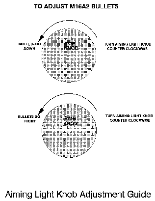
Figure 10
|
| |
|
NEWSLETTER
|
| Join the GlobalSecurity.org mailing list |
|
|
|


|
| |
|
| |
|
NEWSLETTER
|
| Join the GlobalSecurity.org mailing list |
|
|
|