Chapter 11
Shipboard Fire Fighting
Fire aboard ship is a terrifying experience. It is a situation where the crew must work together as a team to survive. To do this you must know the type of fire you are fighting, select the right extinguishing agent, and know how to use the fire fighting equipment aboard ship to put out the fire. Once you understand what fire is, then you can take the proper actions for putting the fire out. This chapter covers the following:
- Definition of fire.
- Classes of fire.
- Effective agents to control and extinguish each class of fire.
- Types of fire fighting equipment.
- Different types of self-contained breathing apparatus.
CHEMISTRY OF FIRE
| 11-1. Oxidation is a chemical process in which a substance combines with oxygen. During this process, energy is given off, usually in the form of heat. Rusting iron and rotting wood are common examples of slow oxidation. Fire, or combustion, is rapid oxidation; the burning substance combines with oxygen at a very high rate. Energy is given off in the form of heat and light. Because this energy production is so rapid, we can feel the heat and see the light as flames. |
| 11-2. All matter exists in one of three states: solid, liquid, or gas (vapor). The atoms or molecules of a solid are packed closely together, and those of a liquid are packed loosely. The molecules of a vapor are not packed together at all; they are free to move about. In order for a substance to oxidize, its molecules must be pretty well surrounded by oxygen molecules. The molecules of solids and liquids are packed too tight to be surrounded by oxygen molecules. Therefore, only vapors can burn. 11-3. When a solid or liquid is heated, its molecules move about rapidly. If enough heat is applied, some molecules break away from the surface to form a vapor just above the surface. This vapor can now mix with oxygen. If there is enough heat to raise the vapor to its ignition temperature, and if there is enough oxygen present, the vapor will oxidize rapidly--it will start to burn. |
| 11-4. What we call burning is the rapid oxidation of millions of vapor molecules. The molecules oxidize by breaking apart into individual atoms and recombining with oxygen into new molecules. It is during the breaking-recombining process that energy is released as heat and light. 11-5. The heat that is released is radiant heat, which is pure energy. It is the same sort of energy that the sun radiates and that we feel as heat. It radiates, or travels, in all directions. Therefore, part of it moves back to the seat of the fire, to the "burning" solid or liquid (the fuel). 11-6. The heat that radiates back to the fuel is called radiation feedback (Figure 11-1). Part of this heat releases more vapor and part of it raises the vapor to the ignition temperature. At the same time, air is drawn into the area where the flames and vapor meet. The result is that there is an increase in flames as the newly formed vapor begins to burn. |
Figure 11-1. Radiation Feedback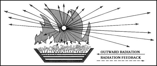
THE FIRE TRIANGLE
11-7. The following are the three things that are required for combustion.
Fuel (to vaporize and burn), oxygen (to combine with fuel vapor), and heat (to raise the temperature of the fuel vapor to its ignition temperature). The fire triangle illustrates these requirements (Figure 11-2). It also illustrates two important facts in preventing and extinguishing fires.
|
Figure 11-2. Fire Triangle With One Side Missing
FUELS AND FUEL CHARACTERISTICS
| 11-8. Fuels and fuel characteristics are important for the mariner to know so that they can identify what fire fighting agent should be used in fighting a fuel fire. |
Solid Fuels
| 11-9. The most obvious solid fuels are wood, paper, and cloth. These can be found aboard ship as cordage, canvas, dunnage, furniture, plywood, wiping rags, and mattresses. The paint on bulkheads is also a solid fuel. Vessels may carry a wide variety of solid fuels as cargo (from baled materials and goods in cartons to loose materials, such as grain). Metals such as magnesium, sodium, and titanium are also solid fuels that may be carried as cargo. |
Ignition Temperature
| 11-10. The ignition temperature of a substance (solid, liquid, or gas) is the lowest temperature at which sustained combustion will occur without the application of a spark or flame. Ignition temperatures vary among substances. For a given substance, the ignition temperature also varies with bulk, surface area, and other factors. The ignition temperatures of common combustible materials is between 149°C (300°F) and 538°C (1,000°F). |
Liquid Fuels
| 11-11. The flammable liquids most commonly found aboard ship are bunker fuel, lubricating oil, diesel oil, kerosene, and oil-base paints and their solvents. Cargo may also include flammable liquids and liquified flammable gases. |
Vaporization
| 11-12. Flammable liquids release vapor in much the same way as solid fuels. The rate of vapor release is greater for liquids than for solids, since liquids have less closely packed molecules. Liquids can also release vapor over a wide temperature range. Gasoline starts to give off vapor at -43°C (-45°F). This makes gasoline a continuous fire hazard; it produces flammable vapor at normal temperatures. Heating increases the rate of vapor release. 11-13. Heavier flammable liquids such as bunker oil and lubricating oil must be heated to release sufficient vapor for combustion. Lubricating oils can ignite at 204°C (400°F). A fire reaches this temperature rapidly, so that oils directly exposed to a fire will soon become involved. Once a light or heavy flammable liquid is burning, radiation feedback and the chain reaction quickly increases flame production. 11-14. The vapor produced by a flammable liquid is heavier than air. This makes the vapor very dangerous because it will seek low places, dissipate slowly, and travel to a distant source of ignition. For example, vapor escaping from a container can travel along a deck and down deck openings until it contacts a source of ignition (such as a spark from an electric motor). If the vapor is properly mixed with air, it will ignite and carry fire back to the leaky container. The result can be a severe explosion and fire. |
Flash Point
| 11-15. The flash point of a liquid fuel is the temperature at which it gives off sufficient vapor to form an ignitable mixture near its surface. Sustained combustion takes place at a slightly higher temperature, referred to as the fire point of the liquid. The flash points and fire points (temperatures) of liquids are determined in controlled tests. |
Gaseous Fuels
| 11-16. There are both natural and manufactured flammable gases. Those that may be found on board a vessel include acetylene, propane, and butanes. |
Burning
| 11-17. Gaseous fuels are already in the required vapor state. Only the correct intermix with oxygen and sufficient heat are needed for ignition. Gases, like flammable liquids, always produce a visible flame; they do not smolder. |
Explosive Range (Flammable Range)
| 11-18. A flammable gas or the flammable vapor of a liquid must mix with air in the proper proportion to make an ignitable mixture. The smallest percentage of a gas (or vapor) that will make an ignitable air-vapor mixture is called the lower explosive limit of the gas (or vapor). If there is less gas in the mixture, it is too lean to burn. The greatest percentage of a gas (or vapor) in an ignitable air-vapor mixture is called its upper explosive limit. If a mixture contains more gas than the UEL, it is too rich to burn. The range of percentages between the lower and upper explosive limits is called the explosive range of the gas or vapor. |
OXYGEN
| 11-19. The oxygen side of the fire triangle refers to the oxygen content of the surrounding air. Ordinarily, a minimum concentration of 16 percent oxygen in the air is needed to support flaming combustion. However, smoldering combustion can take place in about 3 percent oxygen. Air normally contains about 21 percent oxygen, 78 percent nitrogen, and 1 percent other gases, principally argon. |
HEAT
| 11-20. Heat is the third side of the fire triangle. When sufficient heat, fuel, and oxygen are available, the triangle is complete and fire can exist. Heat of ignition initiates the chemical reaction that is called combustion. It can come from the flame of a match, sparks caused by ferrous metals striking together, heat generated by friction, lightning, an oxyacetylene torch cutting or welding metal, an electric short circuit, an electric arc between conductors, or the overheating of an electric conductor or motor. |
CLASSES OF FIRE
11-21. There are four types or classes of fires (labeled A through D) according to their fuels. However, some fuels are found in combinations, and electrical fires always involve some solid fuel. Therefore, for fire fighting purposes, there are actually six classes:
11-22. The main purpose of this classification scheme is to help crew members pick the best extinguishing agent. The choice of an extinguishing agent depends on the class of fire, the hazards involved, and the agents available. It is not enough to know that water is best for putting out a class. A fire because it cools, or that a dry chemical works well in knocking down the flames of a burning liquid. The extinguishing agent must be applied properly and sound fire fighting techniques must be used. |
EXTINGUISHING AGENTS
11-23. An extinguishing agent is a substance that will put out a fire. Every extinguishing agent operates by attacking one or more sides of the fire triangle.
|
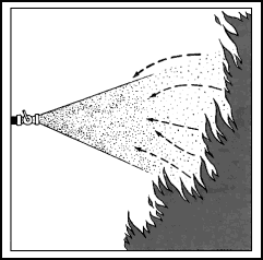 Figure 11-3. Effects of Cooling |
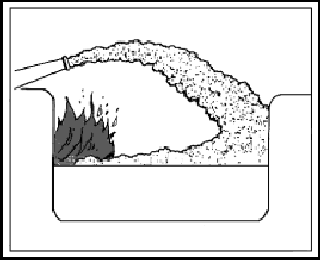 Figure 11-4. Effects of Smothering |

Figure 11-5. Effects of Oxygen Dilution
TYPES OF EXTINGUISHING AGENTS
| 11-24. Eight extinguishing agents are in common use. Each is applied to the fire as a liquid, gas, or solid, depending on its extinguishing action and physical properties. Some may be used on several types of fires, where others are more limited in use (see Table 11-1). |
Table 11-1. The Eight Common Extinguishing Agents
|
|
EXTINGUISHING AGENTS FOR THE DIFFERENT CLASSES OF FIRE
| 11-25. It is necessary to use the most suitable type of extinguishing agent to put out a fire. Select an extinguishing agent that will do the task in the least amount of time, cause the least damage, and result in the least danger to crew members (Figure 11-6). 11-26. Class A fires involve common combustible solids such as wood, paper, cloth, and plastics and are most effectively extinguished by water, a cooling agent. Foam and dry chemical may also be used; they act mainly as smothering agents. 11-27. Class B fires involve oils, greases, gases, and other substances that give off large amounts of flammable vapors. A smothering agent is most effective. Water fog, dry chemical, foam, and carbon dioxide (CO2) may be used. However, if the fire is being supplied with fuel by an open valve or a broken pipe, a valve on the supply side should be shut down. This may extinguish the fire or, at least, make extinguishing less difficult and allow the use of much less extinguishing agent. |
Figure 11-6. Actions of Extinguishing Agents on the Different Classes of Fire
| 11-28. In a gas fire, it is imperative to shut down the control valve before you extinguish the fire. If the fire were extinguished without shutting down the valve, flammable gas would continue to escape. The potential for an explosion, more dangerous than the fire, would then exist. It might be necessary to extinguish a gas fire before shutting down the fuel supply in order to save a life or to reach the control valve; however, these are the only exceptions. 11-29. Combined Class A and Class B fires involve both solid fuels and flammable liquids or gases. Water spray and foam may be used to smother these fires. These agents also have some cooling effect on the fire. Carbon dioxide has also been used to extinguish such fires in closed spaces. 11-30. Combined Class A and Class C fires involve energized electrical equipment and a non-conducting extinguishing agent must be used. Carbon dioxide, Halon, and dry chemical are the most efficient agents. Carbon dioxide dilutes the oxygen supply, while the others are chain-breaking agents. 11-31. Combined Class B and Class C fires involve flammable liquids or gases and electrical equipment. A nonconducting extinguishing agent is required, such as Halon or dry chemical acting as a chain breaker. They may also, in closed spaces, be extinguished with CO2. 11-32. Class D fires involve combustible metals such as potassium, sodium and their alloys, magnesium, zinc, and powdered aluminum. They burn on the metal surface at a very high temperature and often with a brilliant flame. Water should not be used on Class D fires, as it may add to the intensity or cause the molten metal to splatter. This, in turn, can extend the fire and inflict painful and serious burns on those in the vicinity. 11-33. Fires in combustible metals are generally smothered and controlled with specialized agents known as dry powders. Dry powders are not the same as dry chemicals, although many people use the terms interchangeably. The agents are used on entirely different types of fires: dry powders are used only to extinguish combustible-metal fires. Dry chemicals may be used on other fires, but not on Class D fires. |
WATER
| 11-34. Water is primarily a cooling agent. It absorbs heat and cools burning materials more effectively than any other of the commonly used extinguishing agents. Water has an important secondary effect. When it turns to steam, it converts from the liquid state to the gaseous (vapor) state. Seawater is just as effective in fighting first as fresh water. |
Straight Streams
| 11-35. The straight stream, sometimes called the solid stream, is the oldest and most commonly used form of water for fire fighting. |
Efficiency of Straight Streams
| 11-36. The distance that a straight stream travels before breaking up or dropping is called its reach. Reach is important when it is difficult to approach close to a fire. Actually, despite its name, a straight stream is not really straight. Like any projectile, it has two forces acting upon it. The velocity imparted by the nozzle gives it reach, either horizontally or at an upward angle, depending on how the nozzleman aims the nozzle. The other force, gravity, tends to pull the stream down, so the reach ends where the stream encounters the deck. 11-37. Probably less than 10 percent of the water from a straight stream actually absorbs heat from the fire. This is because only a small portion of the water surface actually comes in contact with the fire, and only water that contacts the fire absorbs heat. |
Using Straight Streams
| 11-38. A straight stream should be directed into the seat of the fire. This is important; for the most cooling, the water must touch the material that is actually burning. A solid stream that is aimed at the flames is ineffective. The main use of solid streams is to break up the burning material and penetrate to the seat of a Class A fire. |
Low-Velocity Fog Streams
| 11-39. Low-velocity fog streams are obtained by using an applicator along with a combination nozzle. Applicators are tubes or pipes that are angled at 60° or 90° at the water outlet end. They are stowed for use with the low-velocity head already in place on the pipe. Some heads are shaped somewhat like a pineapple, with tiny holes angled to cause minute streams to bounce off one another and create a mist. Some heads resemble a cage with a fluted arrow inside. The point of the arrow faces the opening in the applicator tubing. Water strikes the fluted arrow and then bounces in all directions, creating a fine mist. 11-40. For 1 1/2-inch nozzles, 4-foot, 60° angle and 10-foot, 90° angle applicators are approved for shipboard use. For 2 1/2-inch nozzles, 12-foot, 90° angle applicators are approved. Other lengths with different angles are sometimes found. The 4-foot applicator is intended for the 1 1/2-inch combination nozzles fitted in propulsion machinery spaces containing oil-fired boilers, internal combustion machinery, or fuel units. 11-41. Low-velocity fog streams are effective in combating Class B fires in spaces where entry is difficult or impossible. Applicators can be poked into areas that cannot be reached with other types of nozzles (Figure 11-7). They are also used to provide a heat shield for fire fighters advancing with foam or high-velocity fog. Low-velocity fog can be used to extinguish small tank fires, especially where the mist from the applicator can cover the entire surface of the tank. However, other extinguishing agents, such as foam and carbon dioxide, are usually more effective. |
Figure 11-7. Low-Velocity Fog Applicators
Limitations of Fog Streams
| 11-42. Fog streams do not have the accuracy or reach of straight streams. Improperly used, they can cause injury to personnel, as in a blowback situation. While they can be effectively used on the surface of a deepseated fire, they are not as effective as solid streams in soaking through and reaching the heart of the fire. 11-43. In some instances, there may be an obstruction between the fire and the nozzleman. Then the stream can be bounced off a bulkhead or the overhead to get around the obstacle (Figure 11-8). This method can also be used to break a solid stream into a spray-type stream, which will absorb more heat. It is useful in cooling an extremely hot passageway that is keeping fire fighters from advancing toward the fire. A combination fog-solid nozzle could be opened to the fog position to achieve the same results. |
Figure 11-8. Bouncing a Straight Stream Off the Overhead
Fog Streams
| 11-44. The fog (or spray) nozzle breaks the water stream into small droplets. These droplets have a much larger total surface area than a solid stream. Therefore, a given volume of water in fog form will absorb much more heat than the same volume of water in a straight stream (Figure 11-9). 11-45. The greater heat absorption of fog streams is important where the use of water is limited. Less water need be applied to remove the same amount of heat from a fire. Also, more of the fog stream turns to steam when it hits the fire. |
Figure 11-9. Advantages and Disadvantages of Straight and Fog Streams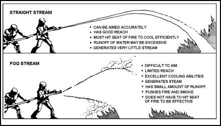
Combination Nozzle Operation
| 11-46. Depending on the position of its handle, the combination nozzle will produce a straight stream or high-velocity fog stream. Combination nozzles are available for use with 1 1/2- and 2 1/2-inch hoses. Reducers can be used to attach a 1 1/2-inch nozzle to a 2 1/2-inch hose. 11-47. Create a straight stream by pulling the nozzle handle all the way back toward the operator (Figure 11-10). Create a fog stream by pulling the handle back halfway. In other words, the handle is perpendicular to the plane of the nozzle (Figure 11-11). Shut down the nozzle, from any opened position, by pushing the handle forward as far as it will go (Figure 11-12). |
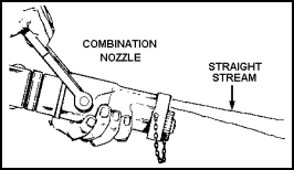 Figure 11-10. Creating a Straight Stream |
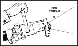 Figure 11-11. Creating a Fog Stream |
Figure 11-12. Shutting Down the Nozzle
| 11-48. The low-velocity fog applicator must be attached with the nozzle shut down. First, the high-velocity tip is removed. Then the straight end of the applicator is snapped into the fog outlet and locked with a quarter-turn. A low-velocity fog stream is obtained with the nozzle handle in the fog position (halfway back). 11-49. When any nozzle is to be used, the handle should be in the closed position until the water reaches the nozzle. The hose will bulge out, and the nozzleman will feel the weight of the water. Before pushing the handle to an open position, he should let the entrained air out of the nozzle. To do this, turn a bit sideways with the nozzle and slowly open it until a spatter of water comes out. Now the nozzle is directed at the target. The backup man closes up to the nozzleman and takes some of the weight of the hose and the back pressure from the nozzle. The nozzle is opened to the desired position, and the fire is attacked. 11-50. Straight and fog streams can be very effective against Class A fires in the hands of skilled operators. Fog streams can also be used effectively against Class B fires. However, it is important that crewmen have actual experience in directing these streams during drills. Applicators should also be broken out at drills so crewmen can get the feel of these devices. |
FOAM
| 11-51. Foam is a blanket of bubbles that extinguishes fire, mainly by smothering. Mixing water and a foam-making agent (foam concentrate) produces bubbles. The result is called a foam solution. The various foam solutions are lighter than the lightest of flammable oils. Consequently, when applied to burning oils, they float on the surface of the oil (Figure 11-13). |
Figure 11-13. Foam
Extinguishing Effects of Foam
11-52. Fire-fighting foam is used to form a blanket on the surface of flaming liquids, including oils. The blanket of foam keeps flammable vapors from leaving the surface and keeps oxygen from reaching the fuel. Fire cannot exist when the fuel and oxygen are separated. The water in the foam also has a cooling effect, which gives foam its Class A extinguishing capability.
11-53. The ideal foam solution should flow freely enough to cover a surface rapidly, yet stick together enough to provide and maintain a vapor-tight blanket. The solution must retain enough water to provide a long-lasting seal. Rapid loss of water would cause the foam to dry out and break down (wither) from the high temperatures associated with fire. The foam should be light enough to float on flammable liquids, yet heavy enough to resist winds.
11-54. The quality of foam is generally defined in terms of its 25 percent drainage time, its expansion ratio, and its ability to withstand heat (burnback resistance). These qualities are influenced by:
|
Figure 11-14. Production of Chemical Foam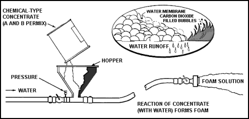
|
Advantages of Foam
11-56. In spite of its limitations, foam is quite effective in combating Class A and Class B fires. Many advantages of foam include the following:
|
Limitations on the Use of Foam
11-57. Foams are effective extinguishing agents when used properly. However, some limitations on foam include the following:
11-59. Many chemical foam systems, both aboard ship and in shore installations, are still in use. However, these systems are being phased out in favor of the newer mechanical foam or, as it is sometimes called, air foam. |
Mechanical (Air) Foam
| 11-60. Mechanical foam is produced by mixing a foam concentrate with water to produce a foam solution (Figure 11-15). The turbulent mixing of air and the foam solution produces bubbles. As the name air foam implies, the bubbles are filled with air. Aside from the workmanship and efficiency of the equipment, the degree of mixing determines the quality of the foam. The design of the equipment determines the quantity of foam produced. 11-61. There are several types of mechanical foams. They are similar in nature, but each has its own special fire-fighting capabilities. Mechanical foams are produced from proteins, detergents (which are synthetics), and surfactants. The surfactants are a large group of compounds that include detergents, wetting agents, and liquid soaps. Surfactants are used to produce aqueous film-forming foam, commonly referred to as AFFF. |
Figure 11-15. Production of Mechanical (Air) Foam
CARBON DIOXIDE
| 11-62. CO2 extinguishing systems have, for a long time, been approved for ship installation as well as for industrial occupancies ashore. Aboard ship, carbon dioxide has been approved for cargo and tank compartments, spaces containing internal combustion or gas-turbine main propulsion machinery, and other spaces. |
Extinguishing Properties of Carbon Dioxide
| 11-63. Carbon dioxide extinguishes fire mainly by smothering. It dilutes the air surrounding the fire until the oxygen content is too low to support combustion. For this reason, it is effective on Class B fires, where the main consideration is to keep the flammable vapors separated from oxygen in the air. CO2 has a very limited cooling effect. It can be used on Class A fires in confined spaces, where the atmosphere may be diluted sufficiently to stop combustion. However, CO2 extinguishing takes time. The concentration of carbon dioxide must be maintained until all the fire is out. Constraint and patience are needed. 11-64. Carbon dioxide is sometimes used to protect areas containing valuable articles. Unlike water and some other agents, carbon dioxide dissipates without leaving a residue. Since it does not conduct electricity, it can be used on live electrical equipment. However, fire fighters must maintain a reasonable distance when using a portable CO2 extinguisher or a hose line from a semiportable system on high voltage gear. |
Uses of Carbon Dioxide
11-65. Carbon dioxide is used primarily for Class B and Class C fires. It may also be used to knock down a Class A fire. It is particularly effective on fires involving:
|
Limitations on the Use of Carbon Dioxide
11-66. CO2 portable extinguishers are used primarily for small electrical fires (Class C) and have limited effectiveness on Class B fires. Their use will be confined to Class B pool fires no greater than four square feet. Successful operation requires close approach due to the extinguisher's characteristics short range (4 to 6 feet).
|
DRY CHEMICALS
| 11-67. Dry chemical extinguishing agents are chemicals in powder form. They should not be confused with dry powders, which are intended only for combustible metal fires. |
Types of Chemical Extinguishing Agents
11-68. Five different types of dry chemical extinguishing agents are in use. Like other extinguishing agents, dry chemicals may be installed in a fixed system or in portable and semiportable extinguishers.
|
Extinguishing Effects of Dry Chemicals
11-69. Dry chemical agents extinguish fire by cooling, smothering, shielding of radiant heat, and by breaking the combustion chain.
|
Uses of Dry Chemicals
11-70. Monoammonium phosphate (ABC, multipurpose) dry chemical may, as its name implies, is used on Class A, Class B, and Class C fires and combinations of these. However, as noted above, ABC dry chemical may only control, but not extinguish, some deep-seated Class A fires and an auxiliary extinguishment method, such as a water hose line, is required. All dry chemical agents may be used to extinguish fires involving the following:
|
Limitations on the Use of Dry Chemicals
11-71. The limitations on the use of dry chemicals are as follows:
|
| WARNING DRY CHEMICAL EXTINGUISHING AGENTS ARE CONSIDERED NONTOXIC, BUT THEY MAY HAVE IRRITATING EFFECTS WHEN BREATHED. FOR THIS REASON, A WARNING SIGNAL, SIMILAR TO THE ONE USED IN CARBON DIOXIDE SYSTEMS, SHOULD BE INSTALLED IN ANY SPACE THAT MIGHT BE TOTALLY FLOODED WITH DRY CHEMICALS. BREATHING APPARATUSES AND LIFELINES MUST ALSO BE AVAILABLE IN CASE CREWMEN MUST ENTER THE SPACE BEFORE IT IS ENTIRELY VENTILATED. TABLE 11-2 DESCRIBES THE SIGNALS THAT ARE USED BETWEEN THE OBA WEARER AND TENDER. |
Table 11-2. Lifeline Signals Between OBA Wearer and Tender
|
| ||||||||||||||||||||||||
DRY POWDERS
11-72. Dry powders were developed to control and extinguish fires in combustible metals. These are Class D fires which involve the following metals:
11-73. Two commercially available dry powders are composed mostly of graphite. The graphite cools the fire and creates a very heavy smoke that helps smother the fire. These agents are also effective on all the metals listed above. They are applied with a scoop or shovel. 11-74. Dry powder with a sodium chloride (salt) base is propelled from portable extinguishers by carbon dioxide and from large containers or fixed systems by nitrogen. The powder is directed over the burning metal. When it drops, it forms a crust on the metal and smothers the fire. Like the graphite types, it is effective on the combustible metals mentioned above. |
HALOGENATED EXTINGUISHING AGENTS (HALON)
11-75. Halogenated extinguishing agents are made up of carbon and one or more of the halogen elements: fluorine, chlorine, bromine, and iodine. Halon 1301 enters the fire area as a gas. Most authorities agree that the Halon acts as a chain breaker. However, it is not known whether it will slow the chain reaction, break it up, or cause some other reaction. Halon 1301 is stored and shipped as a liquid under pressure. When released in the protected area, it vaporizes to an odorless, colorless gas and is propelled to the fire by its storage pressure. Halon 1301 does not conduct electricity. The extinguishing properties of Halon 1301 allow its use on a number of different types of fire. These include:
|
HALON 1301 MAY CAUSE DIZZINESS AND IMPAIRED COORDINATION IF INHALED. IF HALON 1301 IS TO BE USED FOR THE TOTAL FLOODING OF NORMALLY OCCUPIED SPACES, AN EVACUATION ALARM MUST BE PROVIDED. PERSONNEL SHOULD LEAVE THE AREA PROMPTLY ON HEARING THE ALARM. WHEN A HALON 1301 EXTINGUISHER IS USED, THOSE NOT DIRECTLY INVOLVED IN THE OPERATION SHOULD LEAVE THE AREA IMMEDIATELY. THE EXTINGUISHER OPERATOR SHOULD STEP AWAY AS SOON AS THE APPLIANCE IS DISCHARGED. THE AREA SHOULD BE VENTED WITH FRESH AIR BEFORE IT IS REENTERED. IF IT IS NECESSARY TO REMAIN IN OR ENTER AN AREA WHERE HALON 1301 HAS BEEN DISCHARGED, A BREATHING APPARATUS AND LIFELINES SHOULD BE USED. THE ONLY VALID REASON FOR SUCH ENTRY WOULD BE TO SAVE A LIFE OR TO MAINTAIN CONTROL OF THE SHIP. |
HEPTAFLUOROPROPANE (HFC227EA) OR FM-200
| 11-76. HFC227ea or FM-200 is a clear, odorless gas. It has been developed as a total compartment flooding system to replace Halon 1301. As good environmental stewards, the Army has decided on a program of removal of all Halon 1301 fixed firefighting systems aboard vessels. FM-200 will provide the same firefighting capabilities as Halon with a much less harmful effect on the environment. FM-200 is not an ozone-depleting chemical. It works in much the same manner as Halon. The same precautions for the use of Halon should be adhered to when using FM-200. FM-200 can potentiate the effects of adrenalin at concentrations greater than 9 percent. This chemical also produces hydrogen fluoride, a corrosive, when super heated. |
PORTABLE FIRE EXTINGUISHERS
| 11-77. Portable extinguishers can be carried to the fire area for a fast attack. However, they contain a limited supply of extinguishing agent. The agent is quickly expelled from the extinguisher; in most cases, continuous application can be sustained for only a minute or less. For this reason, it is extremely important to back up the extinguisher with a hose line. If the extinguisher does not have the capacity to put the fire out completely, the hose line can be used to finish the job. A crewman who is using an extinguisher cannot advance a hose line at the same time, so the alarm must be sounded as soon as a fire is discovered to alert the ship's personnel to the situation. 11-78. There is a right way and many wrong ways to use a portable fire extinguisher. Crew members who have had little training with these appliances waste extinguishing agent through improper application. At the same time, untrained personnel tend to overestimate their extinguishing ability. Periodic training sessions, including practice with the types of extinguishers carried onboard, are the best insurance against inefficient use of this equipment. Extinguishers that are due to be discharged and inspected may be used in these training sessions. |
CLASSES OF FIRE EXTINGUISHERS
| 11-79. Every portable extinguisher is classified in two ways, with one or more letters and with a numeral. The letter or letters indicate the classes of fires on which the extinguisher may be used. These letters correspond exactly to the four classes of fires. For example, Class A extinguishers may be used only on Class A fires--those involving common combustible materials. Class AB extinguishers may be used on fires involving wood or diesel oil or both. 11-80. The numeral indicates either the relative efficiency of the extinguisher or its size. This does not mean the size of fire on which to use the extinguisher; rather, the numeral indicates how well the extinguisher will fight a fire of its class. 11-81. The NFPA rates extinguisher efficiency with Arabic numerals. The UL tests extinguishers on controlled fires to determine their NFPA ratings. A rating such as 2A or 4A on an extinguisher would be an NFPA rating. (A 4A rating will extinguish twice as much Class A fire as a 2A rating; a 20B rating will extinguish four times as much Class B fire as a 5B rating.) 11-82. The Coast Guard uses Roman numerals to indicate the sizes of portable extinguishers. The numeral I indicates the smallest size and V the largest. A BIII Coast Guard rating indicates a medium-sized extinguisher suitable for fires involving flammable liquids and gases. The Coast Guard ratings of the different types of extinguishers are shown in Table 11-3. |
Table 11-3. United States Coast Guard Extinguisher Classification Table
|
TYPE |
SIZE |
WATER (GALLONS) |
FOAM (GALLONS) |
DIOXIDE (POUNDS) |
CHEMICAL (POUNDS) |
|||
|
A B B B B B C C |
II I II III IV V I II |
2 1/2 |
2 1/2 1 1/4 2 1/2 12 20 40 |
4 15 35 50 100 4 15 |
2 10 20 30 50 2 10 | |||
TEST AND INSPECTION
| 11-83. Army fire regulations require masters or persons in charge to have portable and semiportable fire extinguishers and fixed fire-extinguishing systems tested and inspected "at least once in every 12 months." When tests are completed, a tag will be placed on each extinguisher, showing the date and the person who completed the tests. |
GENERAL SAFETY RULES FOR PORTABLE EXTINGUISHERS
11-84. There are some general safety rules you should follow when using portable extinguishers. These are as follows:
|
WATER EXTINGUISHERS
| 11-85. Extinguishers that use water or a water solution, as the extinguishing agents, are suitable only for Class A fires. There are five types of water extinguishers, but only two are currently produced. In 1969, the manufacture of the inverting types of extinguishers (the soda-acid, foam, and cartridge-operated) was discontinued. However, since a large number of inverting extinguishers are still in use, they will be discussed along with the stored-pressure water extinguisher. |
Soda-Acid Extinguisher
| 11-86. The soda-acid extinguisher (Figure 11-16) comes only in a 2 1/2-gallon size that carries an NFPA rating of 2A. It weighs about 30 pounds when charged, has a reach of 30 to 40 feet, and expends itself in about 55 seconds. The shell of the extinguisher is filled with a solution of 1 1/2 pounds of sodium bicarbonate in 2 1/2 gallons of water. The screw-on cap contains a cage that holds an 8-ounce bottle, half filled with sulphuric acid, in an upright position. A loose stopper in the top of the acid bottle prevents acid from splashing out before the extinguisher is to be used. 11-87. The extinguisher is carried to the fire by means of the top handle. At the fire, the extinguisher is inverted, the acid mixes with the sodium bicarbonate solution forming carbon dioxide gas, and the pressure of the CO2 propels the water out through the nozzle. The stream must be directed at the seat of the fire and moved back and forth to hit as much of the fire as possible. The nozzle should be aimed at the fire until the entire content of the extinguisher is discharged. Remember that water is available for less than a minute! |
Figure 11-16. Water (Soda-Acid) Extinguisher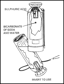
| 11-88. The extinguishing agent, sodium bicarbonate solution mixed with acid, is more corrosive than plain water. The operator should avoid getting the agent on his skin or in his eyes, as the acid could cause burning. Soda-acid extinguishers must also be carefully maintained. When the extinguisher is inverted, a pressure of 130 psi or more is generated. If the container is corroded or otherwise damaged, this pressure could be sufficient to burst the container. |
Cartridge-Operated Water Extinguisher
| 11-89. The cartridge-operated water extinguisher (Figure 11-17) is similar in size and operation to the soda-acid extinguisher. The most common size is 2 1/2 gallons, with an NFPA rating of 2A. It has a range of 30 to 40 feet. The container is filled with water or an antifreeze solution. The screw-on cap contains a small cylinder of CO2; when the cylinder is punctured, the gas provides the pressure to propel the extinguishing agent. |
Figure 11-17. Cartridge-Operated Water Extinguisher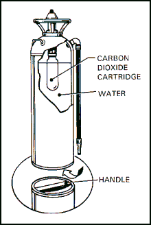
| 11-90. When using the extinguisher, it is first carried to the fire, then inverted and bumped against the deck (Figure 11-18, step 1). This ruptures the CO2 cylinder and expels the water. The stream should be directed at the seat of the fire (Figure 11-18, step 2). The nozzle should be moved back and forth to quench as much of the burning material as possible in the short time available (Figure 11-18, step 3). The discharge time is less than 1 minute. The entire contents of the extinguisher must be discharged, since the flow cannot be shut off. |
Figure 11-18. Using the Cartridge-Operated Extinguisher
| 11-91. As with the soda-acid extinguisher, the container is not subject to pressure until it is put to use. Any weakness in the container may not become apparent until the container fails. |
Pin-Type Cartridge-Operated Extinguisher
| 11-92. A newer version of the cartridge-operated water extinguisher need not be inverted for use. Instead, you can pull the pin out of the cartridge with the extinguisher in an upright position. A lever is squeezed to discharge the extinguishing agent (water or antifreeze solution). 11-93. The cartridge is fitted with a pressure gauge. The gauge should be checked periodically to ensure that the cartridge pressure is within its operating range. Otherwise, maintenance is similar to that for the inverting-type cartridge extinguisher. |
Stored-Pressure Water Extinguisher
| 11-94. The stored-pressure water extinguisher (Figure 11-19) is the most commonly used portable fire-fighting appliance. The 2 1/2-gallon size has an NFPA rating of 2A. It weighs about 30 pounds and has a horizontal range of 35 to 40 feet. In continuous operation, it will expend its water in about 55 seconds. However, it may be used intermittently to extend its operational time. |
Figure 11-19. Stored-Pressure Water Extinguisher
| 11-95. The container is filled with water, or an antifreeze solution, to within about 6 inches of the top (most extinguishers have a fill mark stamped on the container). The screw-on cap holds a lever-operated discharge valve, a pressure gauge, and an automobile tire-type valve. The extinguisher is pressurized through the air valve, with either air or an inert gas, such as nitrogen. The normal charging pressure is about 100 psi. The gauge allows the pressure within the extinguisher to be checked at any time. Most gauges are color-coded to indicate normal and abnormal pressures. 11-96. The extinguisher is carried to the fire, and the ring pin or other safety device is removed. The operator aims the nozzle with one hand and squeezes the discharge lever with the other hand. The stream should be directed at the seat of the fire. It should be moved back and forth to make sure the burning material is completely covered. Short bursts can be used to conserve the limited supply of water. 11-97. As the flames are knocked down, the operator may move closer to the fire. By placing the tip of one finger over the nozzle, the operator can get a spray pattern that will cover a wider area. |
FOAM EXTINGUISHERS
| 11-98. Foam extinguishers are similar in appearance to those discussed previously, but have a greater extinguishing capability. The most common size is 2 1/2 gallons, with an NFPA rating of 2A:4B. This indicates that the extinguisher may be used on both Class A and Class B fires. It has a range of about 30 to 40 feet and a discharge duration of slightly less than a minute. 11-99. The extinguisher is charged by filling it with two solutions that are kept separated (in the extinguisher) until ready to use. These solutions are commonly called the A and B solutions. Their designations have nothing to do with fire classifications. 11-100. The foam extinguisher is carried to the fire right side up and then inverted. This mixes the two solutions, producing a liquid foam and CO2 gas. The CO2 acts as the propellant and fills the foam bubbles. The liquid foam expands to about eight times its original volume. This means the 2 1/2-gallon extinguisher will produce 18 to 20 gallons of foam. 11-101. The foam should be applied gently on burning liquids. Do this by directing the stream in front of the fire and causing the foam to bounce back onto the fire. The stream may also be directed against the back wall of a tank or a structural member to allow the foam to run down and flow over the fire. Chemical foam is stiff and flows slowly. For this reason, the stream must be directed to the fire from several angles for complete coverage of the burning materials (see also Figure 11-20). For fires involving ordinary combustible materials, the foam may be applied in the same way, as a blanket, or the force of the stream may be used to get the foam into the seat of the fire. 11-102. Foam extinguishers are subject to freezing and cannot be stored in temperatures below 4.4° C (40° F). Once activated, these extinguishers will expel their entire foam content; it should all be directed onto the fire. As with other pressurized extinguishers, the containers are subject to rupture when their contents are mixed. Maintenance consists mainly of annual discharging, inspection, cleaning, and recharging. |
Figure 11-20. Operating a Foam Extinguisher on a Flammable Liquid Fire CARBON DIOXIDE (CO2) EXTINGUISHER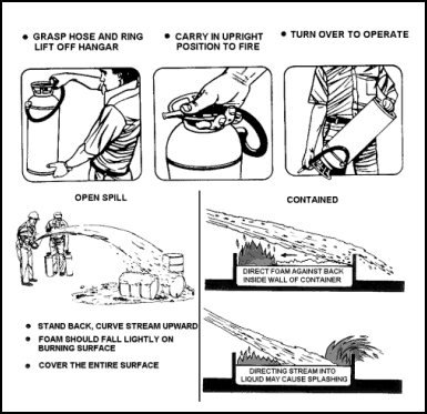
| 11-103. These are used primarily on Class B and Class C fires. The most common sizes of portable extinguishers contain from 5 to 20 pounds of CO2, not including the weight of the relatively heavy shell. The CO2 is mostly in the liquid state, at a pressure of 850 psi at 21° C (70° F). The 5-pound size is rated 5B:C and the 15-pound size has a rating of 10B:C. Depending on the size of the extinguisher, the range varies between 3 to 8 feet and the duration between 8 to 30 seconds. 11-104. Carry the extinguisher to the fire in an upright position. The short range of the CO2 extinguisher means the operator must get fairly close to the fire. Place the extinguisher on the deck and remove the locking pin. The discharge is controlled either by opening a valve or by squeezing two handles together. The operator must grasp the hose handle and not the discharge horn (see Figure 11-21). The CO2 expands and cools very quickly as it leaves the extinguisher. The horn gets cold enough to frost over and cause severe frostbite. When a CO2 extinguisher is used in a confined space, the operator should guard against suffocation by wearing a breathing apparatus. |
Figure 11-21. Procedure for Using the CO2 Extinguisher
Class B Fires
| 11-105. The horn should be aimed first at the base of the fire nearest the operator. The discharge should be moved slowly back and forth across the fire. At the same time, the operator should move forward slowly. The result should be a "sweeping" of the flames off the burning surface, with some carbon dioxide "snow" left on the surface. 11-106. Whenever possible, a fire on a weather deck should be attacked from the windward side. This will allow the wind to blow the heat away from the operator and to carry the CO2 to the fire. CO2 extinguishers generally do not perform well in windy conditions. The blanket of CO2 gas does not remain on the fire long enough to permit the fuel to cool down. |
Class C Fires
| 11-107. The discharge should be aimed at the source of a fire that involves electrical equipment. The equipment should be de-energized as soon as possible to eliminate the chance of shock and the source of ignition. |
Maintenance of CO2 Extinguishers
| 11-108. Several times each year, CO2 extinguishers should be examined for damage and to make sure that they are not empty. At annual inspection, these extinguishers should be weighed. The manufacturer should recharge any extinguisher that has lost more than 10 percent of its CO2 weight. Recharge a CO2 extinguisher after each use, even if it was only partly discharged. |
DRY POWDER EXTINGUISHER
| 11-109. Dry powder (not dry chemical) is the only extinguishing agent that may be used on combustible metal (Class D) fires. The only dry power extinguisher (Figure 11-22) for Class D fires is a 30-pound cartridge-operated model that looks much like the cartridge-operated dry chemical extinguisher. One difference is that the Class D extinguisher has a range of only 6 to 8 feet. The extinguishing agent is sodium chloride, which forms a crust on the burning metal. 11-110. To operate, remove the nozzle from its retainer and press the puncture lever. This allows the propellant gas (CO2 or nitrogen) to activate the extinguisher. The operator then aims the nozzle and squeezes the grips to apply the powder to the surface of the burning metal. |
Figure 11-22. Dry Power Extinguisher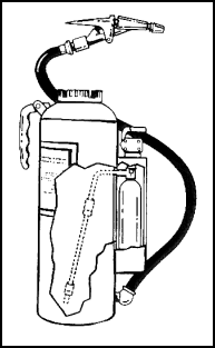
| 11-111. The operator should begin the application of dry powder about 6 to 8 feet from the fire. The squeeze grips may be adjusted for the desired rate of flow to build a thick layer of powder over the entire involved area. The operator must be careful not to break the crust that forms when the powder hits the fire (see also Figure 11-23). |
Figure 11-23. Procedure for Operating the Dry Powder Extinguisher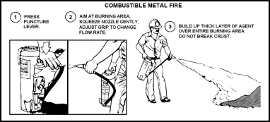
| 11-112. A large amount of dry powder is sometimes needed to extinguish a very small amount of burning metal. A brown discoloration indicates a hot spot, where the layer of dry powder is too thin. An additional agent should be applied to the discolored areas. When the fire involves small metal chips, the agent should be applied as gently as possible so the force of the discharge does not scatter burning chips. 11-113. Class D dry powder also comes in a container, for application with a scoop or shovel. This agent should also be applied very gently. A thick layer of powder should be built up, and the operator should be careful not to break the crust that forms. |
HALON EXTINGUISHERS
| 11-114. Halon 1301 (with an NFPA rating of 5 B:C) is available only in a 2 1/2-pound portable extinguisher. Its horizontal range is from 4 to 6 feet and its discharge time is 8 to 10 seconds. The extinguishing agent is pressurized in a lightweight steel or aluminum alloy shell. The cap contains the discharge control valve and discharge nozzle. 11-115. Carry the extinguisher to the fire and then remove the locking pin. Control the discharge by squeezing the control valve-carrying handle. Direct the Halon at the seat of a Class B fire and apply with a slow, side-to-side sweeping motion. It should be directed at the source of an electrical fire (see Figure 11-24). |
Figure 11-24. Operation of Halon Extinguishers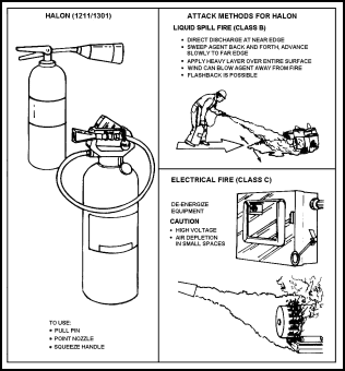
PURPLE-K EXTINGUISHER
| 11-116. PKP extinguishers are dry chemical extinguishers, provided primarily for use on Class B fires. PKP is nontoxic and is four times as effective as CO2 for extinguishing fuel fires. PKP is effective on Class C fires, but do not use if CO2 is available. Also, do not use on internal fires in gas turbines or jet engines because it leaves a residue that cannot be completely removed without disassembly of the engine. 11-117. The PKP extinguisher weighs about 18 pounds and uses CO2 as the expellant gas. The extinguisher shell is not pressurized until it is to be used. Maximum range of the extinguisher is 20 feet from the nozzle and expellant will last for 18 to 20 seconds. Operating procedures (see also Figure 11-25) are as follows:
|
Figure 11-25. Operation of the PKP Extinguisher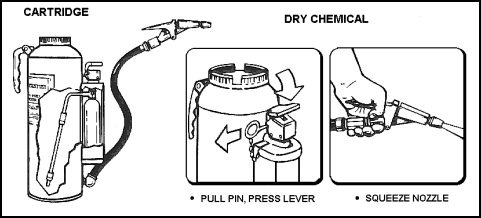
PORTABLE FOAM SYSTEMS
| 11-119. A foam system using an in-line proportioner or a mechanical foam nozzle (with pickup tube) can be carried to various parts of the ship. The foam system is used with the ship's fire-main system. It is an efficient method for producing foam, but it requires more manpower than semiportable systems employing other extinguishing agents. |
Mechanical Foam Nozzle With Pickup Tube
| 11-120. When using, attach the mechanical foam nozzle with pickup tube to a standard hose line from the fire-main system. It draws air in through an aspirating cage in its hose line end. At the same time it introduces mechanical foam concentrate into the water stream through a pickup tube. When the air and foam solution mix, foam is discharged from the nozzle. 11-121. One type of nozzle consists of a 21-inch length of flexible metal hose or asbestos-composition hose, 2 inches in diameter, with a solid metal outlet. A suction chamber and an air port in the hose line end form the aspirating cage. The pickup tube is a short piece of 5/8-inch metal pipe with a short piece of rubber hose on one end. It is used to draw up the contents of a 5-gallon container of foam concentrate. The pickup tube operates on suction created in the suction chamber of the nozzle. |
Operation
| 11-122. The mechanical foam nozzle is screwed onto the fire hose and the pickup tube is screwed into the side port in the base of the nozzle. The metal pipe at the end of the pickup tube is inserted into the foam-concentrate container. When water pressure is applied to the hose, foam concentrate is drawn up to the nozzle where it mixes with the air and water. The resulting foam is applied in the usual manner. The mobility of the foam nozzle is improved if one fire fighter operates the nozzle while another follows with the concentrate container (see also Figure 11-26). |
PORTABLE PUMPS
| 11-123. Portable pumps are a valuable adjunct to the installed pumps of a vessel. They may be used for fighting fires and for removing water from the ship (dewatering). 11-124. The P-250 pump (Figure 11-27) is a self-priming, 250 GPM, portable pump with a 2-cylinder, 2 cycle, 25-horsepower engine. Lubricate the pump by mixing 1/2 pint of 3064 (SAE 30) TEP oil to a gallon of 80- to 100-octane gasoline. Engine cooling is accomplished by pump discharge water passing through the engine. 11-125. This pump is designed for fire fighting and dewatering. The pump is equipped with a 3-inch male intake to which is fitted a 3-inch hard rubber suction hose (10 or 20 feet long) with a foot valve strainer. The discharge outlet is fitted with a 2 1/2-inch male thread to which a 2 1/2-inch hose or a trigate valve is attached. The trigate valve is equipped with a 1 1/2- to 2 1/2-inch thread reducer, making it possible to attach three 1 1/2-inch hoses or one 2 1/2-inch hose. With the reducer removed, a single 2 1/2-inch hose can be used for fire fighting or as the pressure hose for an eductor. The exhaust hose is a 2-inch hard rubber hose. |
Figure 11-26. Using the Mechanical Foam Pick-Up Nozzle Figure 11-27. P-250 Pump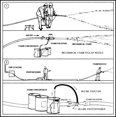

| 11-126. With the foot valve on the suction hose, the P-250 is self-primed by a special primer pump connected to the intake side of the fire pump. However, when the eductor is used or when the lift is greater than 16 to 20 feet, the fire pump must be primed by hand. 11-127. Depending on the amount of water used, delivery pressure may be adjusted within a range of 80 psi to 120 psi. Volume, of course, depends on the number and size of the nozzles. 11-128. Before securing, the portable pump should be flushed out with clean, fresh water. This is to remove salt and any other residue buildup, which may cause the pump to seize. 11-129. The following are the starting procedures for the P-250 pump:
Note: If the suction lift is less than 20 feet, skip the next two steps and then continue.
Note: If the engine is cold, slightly turn the choke control in a clockwise direction.
Note: If the starter engages, hold the START button down until the engine starts. If the starter does not engage, start the engine manually by pulling on the starter rope.
|
SEMIPORTABLE FIRE EXTINGUISHERS
| 11-130. A semiportable extinguisher is one way a hose can be run out to the fire. The other parts of the system are fixed in place, usually because they are too heavy to move. 11-131. The semiportable Halon Hose-Reel System (Figure 11-28) is very similar to the carbon dioxide system. This is used to combat Class B and Class C fires. Most semiportable systems use Halon 1301. The system consists of one or two pressurized cylinders containing the extinguishing agent, a hose line, and a nozzle with an ON-OFF control valve. The system is activated by operating a release mechanism at the top of the cylinder, similar to the CO2 release device. If two cylinders are used, they are both opened when the pilot cylinder is activated. When the agent is released, it travels through the hose up to the nozzle. The hose is then run out to the fire, and the agent is applied as required. |
Figure 11-28. Operation of the Halon Hose-Reel System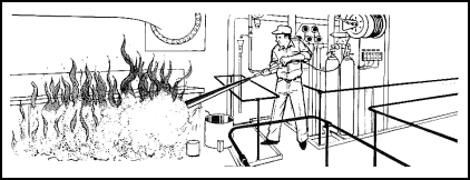
FIXED FIRE STATIONS
| 11-132. The purpose of the fire-main system is to deliver water to the fire stations that are located throughout the ship. A fire station consists basically of a fire hydrant (water outlet) with valve and associated hose and nozzles. All required fire-fighting equipment must be kept in its proper place. Fire stations and hoses must be highly visible and easily put into service. 11-133. Crew members should try to protect all parts of the fire-main system and avoid unauthorized use of the system. Weekly visual inspection of fire stations should be a standard procedure to make sure that all required equipment is in its proper place. Hydrants located on weather decks may become corroded or encrusted with salt, causing their valves to freeze in position and become inoperable. 11-134. Different hydrants should be opened during succeeding weekly fire drills to make sure that water flows from each hydrant at least once every 2 months. This will reduce crusting and rust. When possible, flush out the fire-main system with fresh water to destroy any marine growth in the lines. |
FIRE STATION LOCATIONS
| 11-135. Fire stations are located to ensure that the water streams from at least two hydrants will overlap. Fire hydrants shall be sufficient in number and so located that any part of the vessel, other than main machinery spaces, is accessible to persons onboard while the vessel is being navigated, and all cargo holds may be reached with at least two streams of water from separate outlets. At least one of these streams shall be from a single length of hose. 11-136. In main machinery spaces, all portions of such spaces will be capable of being reached by at least two streams of water, each of which shall be from a single length of hose and from separate outlets. 11-137. Fire stations are numbered. The term "Fire Station" and its number will be stenciled on the bulkhead in numerals at least 2 inches high. |
HYDRANTS
11-138. The fire station hydrant has three major components: a control valve, the hose connection (1 1/2- or 2 1/2-inch) with appropriate threads, and a hose rack (Figure 11-29). Regulations require the following:
|
Figure 11-29. Three Components Of a Fire Station Hydrant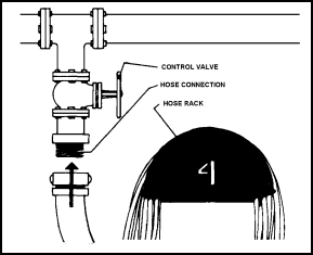
FIRE HOSES, NOZZLES, AND APPLIANCES
| 11-139. The efficiency of a fire station depends largely on the equipment stowed at the station and its condition. A single station should have the following equipment (see also Figure 11-30). |
Figure 11-30. Shipboard Fire Station Equipment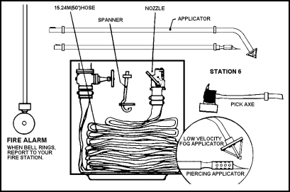
Hoses
| 11-140. A single length of hose of the required size, type, and length is used. Use 2 1/2-inch diameter hose at weather deck locations and 1 1/2-inch diameter hose in enclosed areas. DO NOT use unlined hoses in machinery spaces. The hose couplings must be of brass, bronze, or a similar metal and be threaded with National Standard fire hose coupling threads. The hose must be 50 feet in length. 11-141. The fire hose with the nozzle attached must be connected to the hydrant at all times. However, when a hose is exposed to heavy weather on an open deck, it may be temporarily removed from the hydrant and stowed in a nearby accessible location. Temporarily move the fire hose if there is a possibility that it might be damaged during the handling of cargo. When the fire hose is removed, cover the exposed threads of the hydrant with a thin coating of grease and a protective screw cap. If a screw cap is not available, a heavy canvas, lashed over the threads, gives some protection. Note: The fire hose may not be used for any purpose other than fire fighting, testing, and fire drills. |
Racking and Stowing Hoses
11-142. Most shipboard racks for stowing hoses at fire stations require that the hose be faked. The procedure should include the following steps:
|
Rolling Hose
| 11-144. After using the spare hose, it should be rolled and replaced in stowage. The hose must first be drained and dried. It should then be placed flat on the deck with the female coupling against the deck. The hose is next folded back on itself, so the male coupling is brought up to about 4 feet from the female coupling. The exposed thread of the male coupling should be layered between the hose when the roll is completed. Tie the roll with small stuff to keep it from losing its shape. |
Nozzles and Applicators
| 11-145. Combination nozzles are quite rugged, but are still subject to damage. For example, the control handle can become stuck in the closed position, due to the corrosive action of seawater. Combination nozzles and applicators are often clogged by small pieces of dirt that enter and collect around openings. Periodic testing and maintenance will help detect and correct deficiencies. 11-146. The combination nozzle has a spring latch that allows the high-velocity tip to be released. The latch often freezes into position from misuse. During inspections and drills, the tip should be released and the applicator inserted into position for proper operation. The high-velocity tip should be attached to the nozzle by a substantial chain, so that it cannot be completely separated from the nozzle (see Figure 11-31). |
Figure 11-31. Outlet End of Combination Nozzle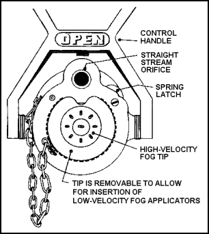
| 11-147. Applicators are strong, but not strong enough to be used as crowbars, levers, or supports for lashing. If misused, the applicator can be crimped or bent along its length. The bayonet end can be damaged so that it cannot fit in the nozzle receptacle. Stow applicators in the proper clips at the fire station. Use applicators for fire fighting and training only. When stowed, applicator heads should be enclosed in sock-type covers to keep foreign matter out. |
Appliances
| 11-148. A spanner wrench (Figure 11-32) is a special tool designed specifically for tightening or breaking apart fire-hose connections. The spanner should match the hose size and butt configuration. Hose-butt lug designs change over the years, making some spanner wrenches obsolete. When new hose is ordered, the available spanner wrenches must be compatible with the new hose couplings, or new spanner wrenches must also be ordered. Note: Most hose connections can be made hand-tight and do not require excessive force. |
Figure 11-32. Spanner Wrenches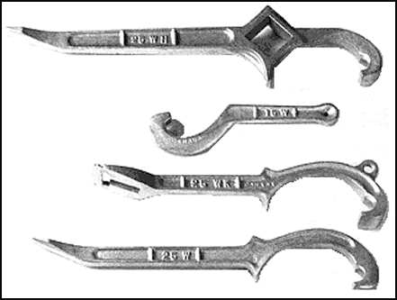
| 11-149. The pike head fire axe (Figure 11-33) is a multipurpose, portable, fire-fighting tool. The pike (pointed) end of the axe may easily be driven through light metal, including metal clad fire doors and some Class C bulkheads. It can be used to make openings quickly and to check for smoke or fire extension. It is also useful for tearing apart mattresses and upholstered furniture and for shattering heavy glass (including tempered glass) when necessary. The broad end of the axe can be used to pry open hinged doors, to remove paneling and sheathing to expose recesses and voids (avenues of fire travel), or to chock doors open. 11-150. Crew members must be cautious when using axes to force a door or break glass. They should wear gloves and other protective clothing, if available. A door should be forced only when necessary. The door should first be checked to see if it is unlocked. If locked, there may be time to obtain a key (especially if the fire is a minor one and lives are not in danger). Otherwise, if a door must be forced, it must be done without hesitation. |
Figure 11-33. Pike Head Fire Axe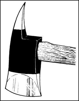
| 11-151. Inspect axes periodically. They should be sharpened, cleaned, or repaired as necessary. The blade and pike ends should be kept sharp and free of burrs. The handle should be tight in the axe head and free of splits and splinters. An occasional light oiling will keep the head from rusting. |
SELF-CONTAINED BREATHING APPARATUS
| 11-152. Although the air encountered at a fire is hot, contaminated by smoke and toxic gases, and deficient in oxygen, crewmen must enter this hostile environment to fight the fire. Their problem is simple, direct, and urgent--they must breathe. The equipment discussed in this paragraph is designed to enable seamen to enter such a hostile environment with some degree of protection for the respiratory system. 11-153. A breathing apparatus is a device that provides the user with breathing protection. It includes a facepiece, body harness, and equipment that supplies air or oxygen. Breathing apparatuses are available in several types. Each type is effective, if used properly. Each one has certain advantages and disadvantages. |
THE DEMAND UNIT
| 11-154. This type will provide air or oxygen from a supply carried by the user. Use the OBA in any atmosphere that contains, has contained, or is suspected of containing flammable or combustible liquids or gases. Never wear the OBA in a cofferdam or any compartment fouled by fuel oil. |
THE STANDARD FACEPIECE
| 11-155. The facepiece is an assembly that fits onto the face of the person using the breathing apparatus. The facepiece forms a tight seal to the face and transmits air or oxygen to the user. The standard facepieces (Figure 11-34 and Figure 11-35) are shown with the breathing apparatus covered in this paragraph. |
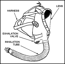 Figure 11-34. Single Hose Facepiece |
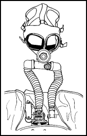 Figure 11-35. Dual Hose Facepiece |
Construction
11-156. The basic part of the facepiece is the mask. It is made of oil-resistant rubber, silicone, neoprene, or plastic resin. Most facepieces include a head harness with five or six adjustable straps, a flexible inhalation tube, an exhalation valve, and a wide-view lens. Some models also include a nose cup or a speaking diaphragm. The facepiece used with oxygen-generating equipment has an exhalation tube and an inhalation tube. Each tube has a mica disk-type valve for airflow control.
|
Use and Maintenance
| 11-157. Donning, stowing, and maintaining the facepiece all affect its efficiency in use. For example, poorly stowed equipment is difficult to put on. Poorly maintained equipment could cause difficulties in achieving an uncontaminated atmosphere within the facepiece. Poorly donned equipment will simply not effectively protect the wearer. |
Putting on the Facepiece
11-158. When the facepiece is put on properly, the chin straps are below the ears. The harness pad is at the back of the head, as close to the neck as possible. The side straps are above the ears. The mask portion is snug, but not tight. Two factors are important when the facepiece is to be put on.
|
Figure 11-36. Steps for Putting on the Facepiece
SELF-GENERATING (CANISTER) TYPE OBA
| 11-160. The self-generating, or canister, type OBA (Figure 11-37) is also a self-contained breathing apparatus. In this unit, the wearer's exhaled breath reacts with chemicals in a canister to produce oxygen. The wearer then breathes this oxygen. |
Figure 11-37. Canister Type OBA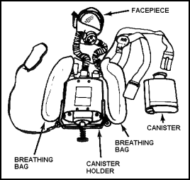
Construction
11-161. The canister-type unit consists basically of five parts:
11-163. The canister contains chemicals that react with moisture in the wearer's exhaled breath to produce oxygen. These chemicals also absorb carbon dioxide from the exhaled breath. If the unit is used for a short time and then removed, a new canister must be inserted before the next use. The chemicals in the canister continue to react even after the facepiece is removed and there is no accurate way of measuring the time left before the chemicals are used up. The breathing bag holds and cools the oxygen supplied by the canister and is made of reinforced neoprene. 11-164. The manual timer is set when the equipment is put into operation. It gives an audible alarm to warn the operator when the canister is nearly expended. The timer is no more than a clock; it does not indicate the condition of the canister. It should always be set to allow the wearer enough time to leave the contaminated area after the alarm sounds. 11-165. The body harness is a series of web straps that position and stabilize the apparatus. The breastplate holds the canister and protects the wearer from the heat generated by the unit. |
Operating Cycle
| 11-166. Figure 11-38 shows the operating cycle of the canister-type unit. The wearer's exhaled breath [1] passes from the facepiece into the exhalation tube and then into the canister. The chemicals in the canister absorb moisture and carbon dioxide [2]. They produce oxygen, which passes from the canister to the breathing bag [3]. When the wearer inhales [4], the oxygen moves from the breathing bag to the facepiece [5] via the inhalation tube. |
Figure 11-38. Sequence of Operating Cycle for OBA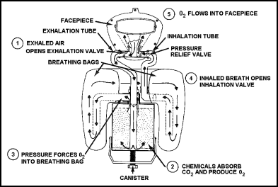
Putting on the OBA
11-167. You can, without too much trouble, put on the OBA without assistance. Do the following steps to put on the OBA.
|
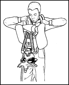 Figure 11-39. Putting on the OBA, Step 1 |
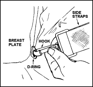 Figure 11-40. Putting on the OBA, Step 2 |
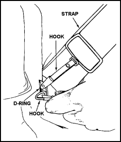 Figure 11-41. Putting on the OBA, Step 3 |
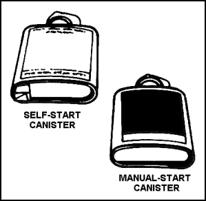 Figure 11-42. Putting on the OBA, Step 4 |
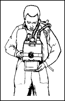 Figure 11-43. Putting on the OBA, Step 5 |
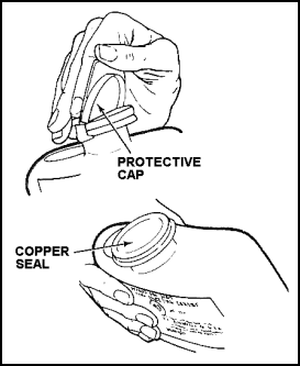 Figure 11-44. Putting on the OBA, Step 6 |
 Figure 11-45. Putting on the OBA, Step 7 |
 Figure 11-46. Putting on the OBA, Step 9 |
 Figure 11-47. Putting on the OBA, Step 10 and 11 |
 Figure 11-48. Putting on the OBA, Step 12 |
| CAUTION: If the lenses fog up, any part of the unit malfunctions, or the wearer experiences any discomfort or difficulty in breathing, he must immediately retreat to safety. One cause of difficulty in breathing is an overinflated breathing bag. If the bag is overinflated, it will seem very hard. This problem can be corrected, in a safe area, by briefly depressing the button in the center of the relief valve. The bag should not be allowed to deflate completely during this process. If the bag becomes underinflated, the user must repeat step 10. |
Removing the Canister
11-168. The removal and disposal of an expended canister are very hazardous operations that must be performed to avoid injury. The procedure (see also Figure 11-49) is as follows:
|
 Figure 11-49. Removing the Canister |
 Figure 11-50. Puncturing the OBA Canister |
Maintenance of Oxygen-Generating Apparatus
11-169. The oxygen-generating apparatus must be maintained carefully. The manufacturer or his representative must replace worn or damaged parts. Those who use the equipment should faithfully perform periodic inspections and after-use maintenance by using the following procedures:
|
Safety Precautions
| 11-170. Certain precautions must be taken when the oxygen-generating apparatus is used. The user must be careful not to damage the breathing bag on nails, broken glass, or other sharp objects. When it is necessary to operate the relief valve, he must do so carefully so as not to deflate the breathing bag too much. 11-171. The instructions on the canister must be followed. Foreign material, especially petroleum products, must be kept from entering an opened canister. The chemical in the canister must not come in contact with the skin. 11-172. The apparatus must not be stowed with a canister already inserted. After one use, regardless of how short, the canister must be discarded as described. For older units without the self-start action, three fresh canisters should always be kept in readiness, with their caps intact, in the storage case. For newer units with the self-start action, two fresh canisters may be kept in the case. |
Advantages and Disadvantages of the OBA
| 11-173. The greatest advantage of the oxygen-generating apparatus is its staying time. The canister produces enough oxygen for comfortable breathing up to 45 minutes, and it is much lighter than other self-contained units. Therefore, it is advantageous for use in large contaminated spaces where ventilation may be difficult, where it is difficult to locate the fire or the source of contamination, and wherever an uninterrupted operating time of up to 45 minutes is needed. 11-174. The following are some disadvantages of the canister-type apparatus:
|
SELF-CONTAINED, DEMAND-TYPE BREATHING APPARATUS
| 11-175. The demand-type breathing apparatus is being used increasingly aboard ships. Its popularity stems from its convenience, the cool fresh air it supplies the user, the speed with which it can be put into service, and its versatility. The demand-type apparatus gets its name from the functioning of the regulator, which controls the flow of air to the facepiece. The regulator supplies air "on demand;" that is, it supplies the user with air when he needs it and in the amount his respiratory system requires. It therefore supplies different users with air at different rates, depending on their "demand." Note: The newer model of the demand-type breathing apparatus is being supplied with a positive flow to the facepiece. The slight pressure in the facepiece prevents contaminated air from entering the facepiece and getting into the respiratory tract. This positive air pressure lessens the critical nature of the facepiece fit against the user's face. 11-176. The self contained, demand-type apparatus consists of four assemblies:
|
BACKPACK UNIT
| 11-177. The backpack unit is the most commonly used demand-type breathing apparatus. Its air supply has a longer duration than that of the sling-pack unit. |
Donning
| 11-178. When a backpack unit has been properly stowed in its carrying case, it can be donned by the user without assistance (Figure 11-51). The unit should be stowed with the tank down, backpack up, and harness straps fully extended. |
Figure 11-51. A Properly Stored Backpack Unit
| 11-179. The high-pressure air hose should be lying along the front of the case, with the regulator at the front right-hand corner. The harness take-up straps must be attached to the chest straps. One should be to the left of the regulator, and the other should be attached to the metal buckle on the right chest strap. The waist straps should be rolled or folded neatly between the backpack and the cylinder valve. The facepiece should be placed between the air cylinder and the high-pressure air hose. 11-180. When the unit has been stowed as described, it is donned in this way:
|
 Figure 11-52. Donning the Backpack |
 Figure 11-53. Donning the Backpack |
 Figure 11-54. Donning the Backpack |
 Figure 11-55. Donning the Backpack |
 Figure 11-56. Donning the Backpack |
 Figure 11-57. Donning the Backpack |
Removal and Restowing
11-181. Remove the backpack unit as follows:
|
 Figure 11-58. Removing and Restowing |
 Figure 11-59. Removing and Restowing |
Figure 11-60. Removing and Restowing 
the Backpack Unit, Step 8
SLING-PACK UNIT
11-182. The sling-pack unit is generally stowed in a case. However, it is donned as follows no matter how it has been stowed:
|
 Figure 11-61. Donning the |
 Figure 11-62. Donning the |
Figure 11-63. Donning the Sling-
Pack Unit, Step 5
|
NEWSLETTER
|
| Join the GlobalSecurity.org mailing list |
|
|
|

