CHAPTER 10
SPECIAL CARGO-HANDLING OPERATIONS
10-1. INTRODUCTION. This chapter discusses three new systems that allow use of ports that may be damaged or underdeveloped. These systems are LOTS, LASH, and SEABEE. This chapter also covers the T-AKR 295/296 Class LOTS operation.
a. By using these three systems, it is possible to unload cargo on the beach and truck it out. The cargo handler oversees the anchoring of waiting vessels in the stream (at sea) several miles off the coast. By not being clustered in one area, these ships are then more protected against enemy strafing and bombing.
b. LASH and SEABEE can also be used to quickly discharge ships in a fixed port. By reducing the time spent in port, they reduce their chances of being attacked by the enemy. The major advantage of all these systems is quick discharge. You must be very familiar with how these systems work to ensure speedy loading and unloading of ships.
10-2. LOGISTICS OVER-THE-SHORE OPERATIONS. Traditionally, a LOTS operation has meant an operation where a vessel anchored in open water was discharged into lighterage and the lighterage was subsequently discharged over a bare beach. This traditional definition has been expanded to include any vessel discharge or loading operation that employs lighterage. Neither the type of facility over which the lighterage is discharged nor vessel anchorage plays any part in the current definition of a LOTS operation. LOTS operations are discussed in detail in FM 55-50 and FM 55-60.
a. The T-AKR 295/296 Class vessels were designed to allow concurrent, in-the-stream, discharge using two LO/LO discharge points and two RO/RO discharge points. As a result, two RRDFs will be required. One to service the sideport ramp and one to service the stern ramp. Additionally, both cranes are capable of concurrently discharging to lighterage on the opposite side of the sideport ramp. Decisions based on vessel discharge at LOTS sites will require detailed information about the available equipment being used in the operation. If no information is available, then it must be assumed that the vessel will discharge using its own lighterage capabilities. In either case, the loading priority needs to be based on the cargo discharge priority. Discharge decisions should also be based on getting the essential equipment for cargo handling off the vessel as quickly as possible. Once this is established, the discharge emphasis should be driven by the ability to run concurrent operations throughout the discharge evolution.
b. There are now three types of LOTS environments. Environments are identified by the type facility over or from which the lighterage can be discharged or loaded. These environments are the fixed-port facility, unimproved port facility, and bare beach facility, all discussed in Chapter 1.
c. Break-Bulk Operations. The process of discharging cargo is discussed below.
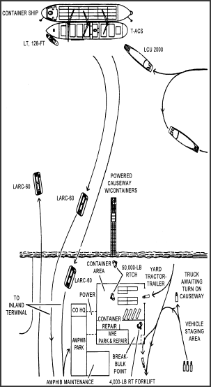
(1) Discharging operations. At a typical LOTS operation (Figure 10-1), break-bulk ships may be anchored from 1 to 5 miles off shore. In order to get the maximum use of the cargo-handling gear aboard each ship and keep a rapid rate of discharge, both sides of the vessel should be worked at the same time. Cargo from holds 1, 3, 5, 7, and so on are discharged over the starboard side and holds 2, 4, 6, and so on are worked over the port side.
WARNING: During periods of adverse weather and for sea conditions, cargo will be discharged over the lee side of the vessel only. At Sea State 2 (1- to 3-foot waves), discharging operations will be limited. At Sea State 3 (3- to 5-foot waves), it is the terminal commander's call. In almost all cases, cargo operations will stop.
- Work lighters on the lee side of the vessel if possible.
- Rig spring lines and mooring lines so that the lighters are positioned directly below the ship's outboard booms.
- When possible, make up unitized loads of small items which can be unhooked and left in the lighter.
- Attach two or more taglines to each draft of cargo in order to control swinging.
- In rough water, land the draft at the crest of the wave. Then slack off the runner immediately to prevent the draft from being hoisted as the lighter falls in the trough of the wave.
- Do not stand in the cargo space when landing drafts in small amphibians or landing craft.
- Do not drop loads onto a lighter deck.
- For safe handling, reband damaged palletized cargo before it is discharged.
- Never pull a cargo draft into position; you might slip and fall underneath the draft. Always push the draft into place.
- Properly load, block, and secure vehicles to be carried in the lighters. The vessel master will ensure that the vehicles are inspected and deemed secure before movement.
(a) Cargo handlers should follow these general rules when discharging cargo vessels in the stream to lighters:
(b) During discharge operations, personnel should be constantly alerted for new ways to speed up cargo movement. For example, when operating conditions are favorable, empty semitrailers can be backed onto landing craft. Cargo may then be loaded into the semitrailer at shipside. When the landing craft is beached, the semitrailer is towed directly from the landing craft to the depot or to the temporary area. This action eliminates a shoreline transfer operation.
(2) Cranes. Use of cranes in a LOTS operation requires highly skilled operators, thoroughly familiar with the capabilities and limitations of the equipment. Exceeding crane limit can topple the crane. When a crane is located aboard ship, or on a floating platform, the danger is increased by wind and water action. Pendulum action of suspended cargo may easily damage the ship, other equipment, and cargo or more importantly, injure personnel.
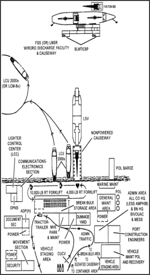
Figure 10-1. Typical LOTS operation (not to scale)
- A signalman in the hold of the ship, to direct the engagement of the spreader bar.
- A signalman on deck, on the near side of the ship, visible to the crane operator when visual signals are used.
- A signalman on the pier, visible to the crane operator, and positioned where the operator can direct the cargo lowering onto the transporter. (In a LOTS operation, a crew member of the receiving piece of lighterage performs this task.)
- A signalman on deck, visible to the crane operator and to the signalman in the hold.
- Two to four tagline handlers to align and steady the container as it is lowered onto the transporter.
(a) Normally with the assistance of a forklift, a rough terrain crane unloads the cargo from the landing craft and loads it into a truck. If cargo cannot be cleared for shipment immediately, it is transferred by truck to a temporary holding area.
(b) Unless protected from surf action, the sand may be washed from under the wheels of the rough terrain crane, which could then tip over when picking up a lift. If possible, operate the crane from a floating platform, or make a platform from sandbags or some other material that will hold against the washing action of the surf. Use perforated splashboard on the seaward side of the wheels to break surf action and retain sand under the wheels.
(c) In the case of non-self-sustaining ships, two cranes work the ship anchored offshore. These two cranes are positioned on a floating platform alongside it, or if it is available, TAK-C ship is used.
(d) Protect cranes from the corrosive action of salt water. A heavy coating of grease and frequent washing down with fresh water protects against this danger.
(e) No matter how skilled he may be, a crane operator requires assistance in the form of signalmen and tagline operators. The number varies with the situation, but a typical crew might include-
(3) Other equipment and vehicles. Listed below are other equipment and vehicles used in LOTS operations.
(a) The RTCH is normally used in a LOTS operation. It can stack 40-foot containers (not exceeding 50,000 pounds gross weight), two high when loaded, or three high when empty.
(b) Pontoon causeways or barges will help in the unloading of motor vehicles. Causeways made of sandbags or other solid material, reaching from the shoreline to the beaching area for large landing craft on shallow beaches, can also be used. These causeways will eliminate the possibility of drowning out, because vehicles can roll ashore without passing through the water.
(c) When barges are used in discharge operations, however, stowage of cargo aboard and movement of the cargo to the hook of fixed or mobile shore-based cranes may present a problem. The use of forklift trucks aboard a barge and a crawler crane located alongside on a separate barge are useful.
10-3. LASH AND SEABEE OPERATIONS. The barge ship system is a relatively new concept in ocean transportation. It consists of a barge-carrying ship and a fleet of cargo lighters. Under this system, lighters loaded with cargo are discharged from the barge-carrying ship. The principal advantage of this system is its ability to load and discharge barges rapidly and minimize turnaround time. There are two types of barge ship systems in operation: the LASH and the SEABEE.
a. LASH. LASH ships feature a 500-ton gantry crane for loading and unloading the lighters. The lighter crane traverse the entire length of the main deck with lighters stowed two high on the hatch covers of each hold. The crane runs on heavy-duty rails located directly over the ship's side bulkheads. These bulkheads extend outward at the stern in the form of twin cantilever structures. The crane's lifting frame operates similarly to a container lifting frame. It is self-centering in the lighter's stacking posts. This frame is equipped with positive latching arrangements to ensure a safe lift.
(1) Some LASH ships also carry a self-propelled 35-ton gantry crane for the loading and unloading of containers.
(2) All lighters are approximately 61 feet 6 inches by 31 feet 2 inches by 13 feet deep. LASH lighters are designed with 36 tie-down fittings along the side walls and end bulkheads. The fittings are rated at 40,000 pounds each. They are useful for tomming down loose cylindrical items or securing large loads. Two levels of fittings extend around the entire interior of the lighter. The first level, with five fittings on each side and four on the ends, is 2 feet 6 inches above deck. The second level also has five fittings on each side and four on the ends and is located 8 feet above the deck.
b. SEABEE. The SEABEE is arranged differently from the LASH. The ship has three decks on which the cargo barges or container flats are stowed. Barges are towed to the ship, the ship's stern elevator is lowered, and the barges are floated over the elevator. With the barges seated on supporting pedestals, the elevator then raises the transporter moves onto the elevator and hydraulically jacks the barge up to move it to its stowage position. The barge is lowered into position and secured next. Lower decks are loaded first and discharged last. On the average, a loading cycle takes up to 40 minutes. Two barges can be lifted with each cycle.
(1) Some container cargoes are stowed on specially designed adapter flats, separate from the lighters. Cargo containers are then lifted aboard ship by the same shoreside crane used for other container lifts. A barge-mounted crane can be used in the stream. The flats, about half the length of a SEABEE barge, are put on the weather deck only. They are supported and secured in the same manner as the barges. Twenty- and forty-foot containers may be stowed aboard these adapter flats and atop the barges on the main deck. Thirty-foot containers also can be stowed within the SEABEE barges.
(2) The SEABEE barges are larger than their LASH counterparts. This gives them more than twice the deadweight and bale cubic capacity for cargo than a LASH. These barges are general-purpose dry cargo units fitted with lift-off construction which greatly decreases the likelihood of cargo damage from flooding or collisions.
c. Preload Operations. LASH and SEABEE operations follow the same general principles of loading that govern any oceangoing vessel. However, some preload procedures are special to LASH and SEABEE operations.
(1) On lighters equipped with removable hatch pontoons, only remove as many covers as necessary to load the barge safety. Leaving the remaining covers in place reduces start-up and cover-up delays. In addition, this practice provides greater protection from weather conditions. Also, hatch covers left in place make an acceptable location for the cutting or assembly of dunnage.
(2) Remove hatch covers by using a four-leg sling at least 10 feet in length. Covers should always be lifted vertically, since dragging them along a hatch cover will damage the waterproof gasket on the underside. This will result in the lighter losing its weatherproof seal. Stack covers on a flat surface to prevent distortion and additional gasket damage.
(3) Report lighters arriving with damaged or missing gaskets to the shipping contractor.
(4) Check the lighters to determine if there is any leakage in the void spaces of the double hull. Any water taken on by the lighter will decrease the maximum amount of cargo weight that can be stowed. A fully loaded lighter with water in its void spaces could easily exceed the capacity of the ship's gantry crane. To determine accurately if any water is present in the void spaces, take soundings through plugs on opposite corners of the lighter. Take care to keep the sounding plugs tightly in place.
(5) Maintain inspection policies for lighters that are identical to policies for merchant-type ships. One exception is that each lighter is considered to be a separate compartment. Each must be signed off individually by authorized loading personnel, inspectors, and shipping contractor representatives.
d. Preliminary Stowage Plans. A preliminary stowage plan including the cargo, the load weight, and the dimensions of the individual unit loads should be developed for each lighter (Figure 10-2). In order to use the rectangular stowage area of the lighter efficiently, cargo handlers should block-stow the cargo. Because of the relatively narrow width of the lighters, maximum space usage requires rectangular unit loads to be placed in different directions. In each case, the proper positioning of the loads is reflected by the preplan.
e. Final Stowage Plan. In the final stowage plan, the commodity description, number of pieces, tonnage, and port sequence are entered as shown in Figure 10-3. Empty spaces within the cargo stow are caused by cargo sizes that are not even multiples of the lighter's interior dimensions or by stacking posts and access ladders that extend into the cargo area. The different ways of shoring these voids determine the types of block stow that may be used in loading lighters. The types of block stow discussed in this chapter are block stow, staggered block stow, and modified block stow.
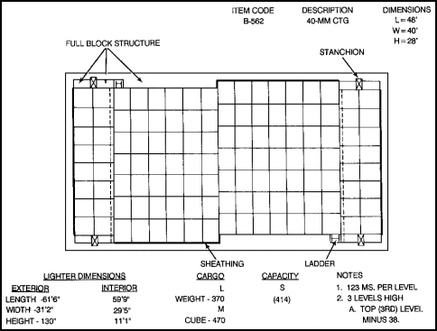
Figure 10-2. Lighter prestowage plan
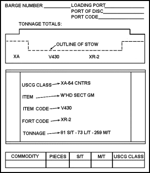
Figure 10-3. Final stow plan
f. Block Stow. Before building encasement structures and installing sheathing material, cargo handlers begin block stowage at both ends of the barge. The cargo may be stowed alternately against each side, and can continue to be loaded by moving toward the centerline. Empty spaces should be planned along the athwartship and the longitudinal centerline. For all practical purposes, the lighters are considered an amidship tween deck compartment. Figure 10-4, shows the development of a block stow in a LASH lighter.
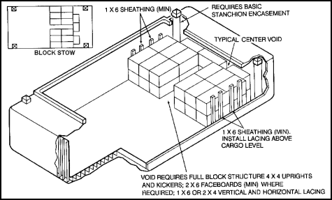
Figure 10-4. Block stow
g. Staggered Block Stow. The procedures for this type of block stow are discussed below.
(1) This variation of the conventional block stow pattern calls for cargo to be stowed tightly against the diagonally opposite side bulkheads of the lighter. Cargo handlers should start the stow at each end of the lighter. Cargo should be stored in a tight pattern across the lighter until the last load is fitted into place. The empty space that remains between the completed stow and the hull of the lighter is shored with a full block structure. The structure is similar to the one constructed on the lengthwise centerline in the conventional block stow technique. Cargo handlers should continue stowing by moving back toward the athwartship centerline. The remaining empty spaces are shored with full block structures.
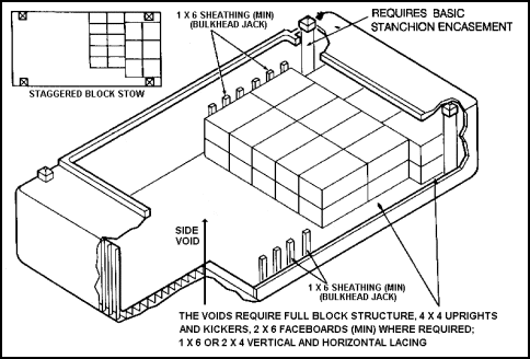
(2) The staggered block stow pattern is shown in Figure 10-5. The lighter remains balanced by offsetting the loads in opposite directions around the long centerline. Staggered block stow allows for easy operation of the forklift truck in the square of the hatch. This is because these stowage operations take place in opposite corners of the lighter. Sheathing and encasement structures are required only on one side and at the ends of the barge. In addition, the smooth steel construction of the lighter's side bulkhead allows for block structure of cargo. This is especially true if the cargo stow consists of mixed commodities of varying dimensions. Figure 10-5 shows a typical shoring structure installed at the hull when using the staggered block stowage technique.
h. Modified Block Stow. The procedures for this type of block stow are discussed below.
(1) When the hull angles are almost straight up and down, overstowed unit loads are no longer offset and the sweatboard-to-sweatboard technique resembles block stowage. However, since the empty spaces in the center of the stow can still be shored in accordance with sweatboard-to-sweatboard procedures, the modified block stowage pattern can be used (Figure 10-6).
Figure 10-5. Staggered block stow
and bulkhead jack
(2) As with conventional block stow, stowage operations begin at both ends of the barge with workers placing cargo tightly against sheathing and basic encasement structures. Voids that occur in the center of the stow are staggered between tiers so that they do not occur directly over each other. Voids in the lower tiers that are less than one-third the width of a unit load do not require shoring. Large voids require vertical support and use of a void table. Only voids in the top tier require full block structures. Detailed void shoring techniques are discussed in TM 55-607. Unlike the conventional sweatboard-to-sweatboard stowage technique, tier stripping is not normally required. This is because palletized unit loads are not offset and voids never occur under two unit loads. Skidded unit loads of items palletized on metal adapters require tier stripping for adequate support. The modified block stowage pattern eliminates the need for large full block structures. Only basic encasement, shoring, void tables, and top tier block structures are required.
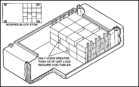
Figure 10-6. Modified block stow
i. Stowage Arrangements. When stowing cargo in lighters, cargo handlers stow barges aboard the ship in the athwartship direction. Thus, cargo placed fore and aft with respect to the lighter is actually positioned athwartship with respect to the mother ship. Overhanging unit loads which are stowed both in the fore-and-aft direction and athwartship within a lighter should be positioned with their greatest bearing surface against the sheathing.
10-4. BLOCKING AND BRACING ABOARD LIGHTERS. Since lighters are an individual dry cargo hold, the general blocking and bracing techniques presented in Chapter 8 apply. Unlike a break-bulk cargo vessel, the basic interior dimensions of a lighter do not vary significantly for different designs. Consequently, many dunnage structures are prepared in advance of the actual loadout operation. Here are some procedures for blocking and bracing structures unique to lighter loading.
a. Sheathing. Sheathing is required between the cargo and the smooth steel sides of a lighter. The sheathing protects cargo from moisture condensation on the inner bulkheads. Since this material will normally be in compression between the cargo and the smooth steel sides of the barge, cargo handlers should use only 1- by 6 inch or 2- by 4-inch material above the cargo. The use of reclaimed lumber is also acceptable for sheathing. However, the lumber must be inspected to ensure that all nails have been removed. In situations where empty spaces are left at the hull of the barge and full block structures must be built, sheathing should be at least 2- by 4-inch lumber in order to receive nails from the kickers.
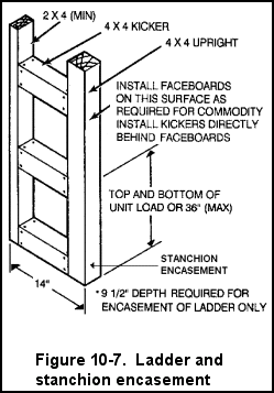
b. Encasements. The four stacking posts and two access ladders found in lighters must be encased to provide a firm bearing surface for the stowage of cargo. Whenever cargo is to be stowed tightly against these obstructions, basic bulkhead jacks are constructed (see Figure 10-5). Since the sizes and location of each of these obstructions is known, the shoring structures will not vary in size and can be made in advance. Figure 10-7 provides construction details for encasement of a stanchion which are the same as those for a stacking post. The stacking post protrudes approximately 14 inches into the lighter hold. Jacks should be spaced on either side of the stanchion. Nail boards measuring 2 by 6 inches over the face. Boards should be spaced equally with the top and bottom of the unit loads stowed against them.
(1) The encasement structure should extend out an even number of rows of cargo. On the sides of the barge containing the access ladders, the structure is extended out to include the ladder, which protrudes approximately 9 1/2 inches into the compartment. Normally, the encasement structure would be extended flush over the ladder (see Figure 10-7).
(2) Where stowage space is at a premium, the encasement structure is "cut back" after the stacking post, using 9 1/2-inch jacks on either side of the ladder. In any case, cargo handlers should never secure cargo so that its weight is borne by the access ladder because the ladder is relatively weak.
c. Partial Stow Bulkheads. Normally, it is better to stow cargo in lighters in full layers to minimize time-consuming securing of the partial top layer. For many shipments, however, maximum space utilization requires the stowage of a partial top layer. In these situations, cargo handlers secure the partial top layer by using either a step-down structure or a diagonally braced bulkhead.
(1) Use of a step-down structure, described in TM 55-607, is the simplest way to secure a partial top layer (Figure 10-8). Cargo handles should stow cargo the required number of 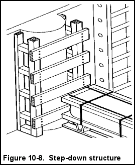 tiers high to a point shown on the preplan. At this point, two 4- by 4-inch uprights should be placed against each stack of unit loads, and laced from behind with 1- by 6-inch or 2- by 6-inch material. Face boards must be installed before placement of the upright when required (usually for overhanging unit loads). Cargo handlers should resume cargo stowage on the other side of the structure at a reduced height. Step-down structures are not to be used when stepping down cargo more than one tier. Also, these structures should not be used when the cargo on the lower side of the structure is lighter than the higher stowed cargo. Instead, cargo handlers should install a diagonally braced bulkhead. In addition, a step-down structure requires approximately 4 inches of space in the stow for insertion of uprights whenever it is used.
(2) A diagonally braced bulkhead, in addition to providing great strength, is used to secure a partial top layer in a lighter. This bulkhead is especially useful where a tight stow does not permit the insertion of uprights between rows of unit loads, as required for a step-down structure. Figure 10-9, shows the construction details of this bulkhead and its usage in lighters. It should be noted that the runners of the bulkhead run to another bulkhead at the other end of the barge where the opposite half of the partial top layer is secured.
d. Division or Partition Bulkheads. These types of bulkheads are used in lighters whenever the items of cargo need to be separated because of incompatibility and cargo configuration.
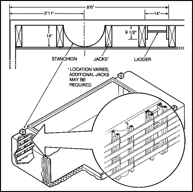
Figure 10-9. Diagonally braced bulkhead
(1) Figure 10-10 shows the construction of a partition bulkhead in a LASH lighter. For compatibility purposes, present Coast Guard policy considers a LASH lighter's equivalent to be a compartment on a merchant ship.
(2) Cargo handlers should shore voids occurring within the cargo stow in accordance with block stow void shoring techniques. Normally, two 4- by 4-inch uprights are placed against each stack of unit loads on the sides of the void. Cargo handlers should kick the uprights against each other, using 4- by 4-inch lumber, and lace them together with 1- by 6-inch or 2- by 4-inch material. If the staggered block stow pattern is used, the void will occur along the side of the barge. Cargo handlers should use 2- by 4-inch uprights on the side of the full block structure against the steel hull. If the modified block stow pattern is used, top tier voids are shored with the full block structures. Face boards are used to resist forces in the opposite direction of the kickers. These boards must be cut to the exact width of the unit loads. Void tables are constructed where needed for lower tier voids. The height and width of the tables should match that of the adjacent unit loads. Crew members should construct both the full block structure face board assemblies and the void tables in advance for specific unit loads.
e. Tomming. Tomming of loose cylindrical, light, or shock-sensitive items aboard a barge is difficult because of the absence of overhead structures. A-frame tomming structures are used at the fore-and-aft areas of the barges, since the small deck area provides limited overhead structure. Cargo stowed in the square of the hatch that approaches the hatch covers in height requires tomming. In other situations, the use of wire rope tie-downs and turnbuckles is recommended. The recessed tie-down fittings located along the hull of the barge are used for hook-in points. Cargo handlers should use dunnage over the cargo to prevent chafing.

Figure 10-10. Partition bulkhead
|
NEWSLETTER
|
| Join the GlobalSecurity.org mailing list |
|
|
|


