Part Three. Special Considerations
Chapter 9
Alternative Well Construction
9-1. Fundamentals. Under special conditions, methods other than the rotary and down-hole hammer may be more expedient for well drilling. Conditions favoring less standard methods include the following:
- Availability of local, nonstandard drilling equipment and qualified personnel.
- A shallow aquifer that can be developed quickly without mobilization delays.
- Availability of unskilled personnel only.
- Requirements for a small water supply.
9-2. Jetted Wells. In the jetting method, you dig a borehole using a high velocity stream of water. The stream loosens the soil and washes the fine particles up and out of the borehole. The jetting method is particularly successful in sandy soils when the water table is close to the surface. Jetting is simple and dependable, and you use hand tools rather than bulky drilling equipment. Two jetting procedures are available washing in a casing or sinking a self-jetting well point. With the jetting method, you can sample the general character of a formation by examining the cuttings brought to the surface in the return flow.
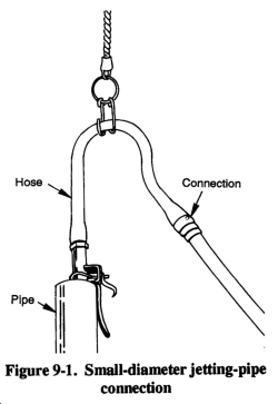
(1) Swivel. The water swivel must be able to carry the weight of the drill pipe and must sustain the maximum pressure delivered by the pump. Figure 9-1 shows a connection that you may use at the top of small-diameter jetting pipes in place of a swivel.
(2) Drive Weight. This is weight you drop on the pipe to help penetrate clayey or semifirm soil.
(3) Jetting Fluid. Water is commonly used in jetting, but a fluid with greater viscosity and weight may be prepared with clay or commercial bentonite. However, a heavier fluid tends to seal the borehole wall, preventing water penetration. In the jetting process, fluid is led from the borehole to a pit where cuttings settle to the bottom. The jetting pump then recirculates this fluid. Under certain conditions in the Arctic, steam is used to construct jetted wells.
(4) Hoist. You need a hoist to handle the drill pipe and casing. You may use hand-operated equipment such as a tripod with tackle. If available, you should use a percussion-type drilling rig with a power hoist (Figure 9-2).
(5) Pump. A pump with suitable hose connection able to deliver 50 to 100 GPM at 50 psi is adequate. The quantity of water needed to jet a well varies with the type of sediment being penetrated. Sand requires the most water; however, high pressure is not necessary. A nozzle pressure of 40 psi is usually sufficient. Clay and hardpan require less water. However, they are not readily displaced except by a small cutting stream delivered at high pressure. You can get a pressure of 200 psi from small nozzles in the drill bit.
(6) Bits. In soft soil, you may use a paddy or expansion bit to make a hole that is slightly larger than the casing. Use the percussion method with a hand rig and straight bits to penetrate hard layers. Use drill-like bits with heavier rigs to penetrate hard layers that do not yield to the water jet. See Figure 9-3 for bits used in jetting.
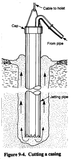
(1) Wash-In. Before washing the casing into the hole, cut the lower end of the casing to form a toothed cutting head (Figure 9-4). Normally, four to six 1-inch long (minimum) teeth are sufficient. Use the following steps to complete the wash-in method:
- Step 1. Mark the outlines of the teeth on the casing using a power drill or cutting torch. Drill or cut holes in the casing to form the gullets of the teeth.
- Step 2. Cut the sides of the teeth with a hacksaw or an oxyacetylene torch to meet the outside circumference of the drilled holes. Rounded holes are desirable so the teeth can readily clear themselves of gravel or other material. Bend half the teeth outward so they cut a hole slightly larger than the casing.
- Step 3. Place a cap on the top of the casing, and attach the discharge hose from the pump to the connection provided in the top of the cap. Suspend the casing vertically, using a hoist. Lay the cutting head on the ground, preferably in a shallow, hand-dug hole. The majority of the casing's weight should rest on the ground.
- Step 4. Operate the jetting pump at full capacity. The casing will fill with water and begin to sink by its own weight as the ground is washed out from under it. The hoist must keep sufficient tension on the casing to hold it vertical. If resistance stops the downward movement of the casing, lift it up 2 or 3 feet and then drop the casing.
- Step 5. Use chain tongs or wrenches to rotate the casing so the teeth at the lower end will cut into the bottom of the borehole. If you wash in more than one length of casing, keep the borehole and first length of casing full of water while attaching the second pipe length and connecting the pump to the pipe. Doing so maintains fluid pressure against the borehole wall and should prevent caving.
- Step 6. Stop the pump, and remove the cap at the top of the casing when the casing reaches the desired depth.
If the casing is permanent, telescope a well semen through the casing until it rests on the bottom of the well. Pull the casing up until the screen is exposed to the aquifer and cut the casing off at a point about 1 foot above the ground surface. If the casing is temporary, attach a well pipe to the screen before lowering it into the casing. When the screen is resting on the bottom of the borehole, pull the entire casing out of the borehole. You can reuse this casing.
(2) Self-Jetting. Figure 9-5 shows the well-point types needed in self-jetting. The continuous slot has a semen constructed of a narrow ribbon of metal wound spirally around a skeleton of longitudinal rods. The brass jacket consists of a woven wire gauze wrapped around a perforated pipe and covered with perforated brass sheet. The jetting head contains a spring-loaded disk or balltype valve that opens when water is forced through during the jetting operation. The valve closes automatically when jetting stops or the well is completed and pumping begins.
Use the following steps for the self-jetting method:
- Step 1. Couple the well point to the bottom of the riser or well pipe. Attach the swivel to the other end of the well pipe. Connect the discharge hose of the pump to the swivel, and dig a shallow hole.
- Step 2. Upend the well-point assembly with the well point standing vertically in the hole. Start the pump and partially open the discharge valve. The jet of water will displace the self-closing valve in the well point and flow through the openings in the head. The soil is washed from under the well point, allowing the point to sink into the ground. Using an up-and-down movement of the well-point assembly will speed penetration.
- Step 3. Increase the water flow by opening the pump discharge valve more as jetting continues. Inmost sands, a pressure of 40 psi at the well-point nozzle will displace soil readily. You may need pressures of 100 to 150 psi to move gravel or penetrate clay. If a regular jetting pump is not available, two standard centrifugal pumps operating in series may work satisfactorily.
- Step 4. Remove the hose from the riser pipe, and couple the pipe to the suction side of the pump after sinking the well point to the desired depth.
- Step 5. Develop the well by quickly opening and closing the discharge valve while operating the pump at a moderate speed. Continue this operation until you clean out all of the fine material from the well-point screen.
(3) Casing and Completion. Jetting fluid effectively prevents caving or collapse of the drilled hole. Insert the casing in a single string only after jetting reaches the full depth. If you do so before, the casing sinks as fast as jetting proceeds. If you encounter too much resistance, you may have to force the casing down. For depths of 200 to 300 feet, you can use a casing of 4-inch diameter pipe. If you sink a deeper well, place a smaller string (3-inch diameter pipe) inside the first string.
To complete the jetted well, connect a hose to the exposed end of the well pipe and couple it to the pump intake. The well will yield water immediately if the pump is in good condition and you have properly placed the well screen. When you first start pumping, a considerable amount of fine sand will be drawn into the well screen and be discharged with the water. Because of this action, direct the water stream into the annular space around the well pipe at the ground level. Doing so washes the coarse sand and gravel into the borehole and packs the sand and gravel firmly around the well screen and pipe. The well is then ready for continuous pumping.
9-3. Driven-Point Wells. Small-diameter driven wells are constructed by driving a drive point fitted to the lower end of tightly connected pipe sections into the ground (Figure 9-6). The drive point consists of a perforated pipe with a steel point at its lower end to break through pebbles or thin hard layers. Use 5- to 6-foot pipe sections for the pipe string and as the casing for the completed well. Driven wells are usually 1 1/4 to 2 inches in diameter. The small diameter pipe required for these wells is light and portable and is easy to install. You can also construct wells up to 4 inches in diameter. The casing used in these wells is heavier and more difficult to drive. However, you can install deep-well pumps in the pipe casing to a depth of 25 feet or more below ground. If you use a common pitcher or a centrifugal pump, the water level should not be deeper than 25 feet.
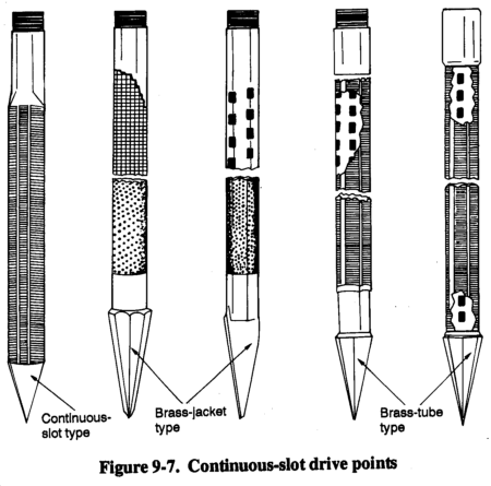
(1) Drive Points. The continuous-slot drive point (Figure 9-7) has a screen with horizontal openings and one-piece welded construction and contains no internal perforated pipe to restrict the intake area. The pipe will withstand hard driving but should not be twisted while being driven.
The brass-jacket type consists of a perforated pipe wrapped with wire mesh and covered with a perforated brass sheet. Because the pipe body must be strong, the number and size of holes are limited, restricting the effective intake area.
The brass-tube type consists of a brass tube slipped over perforated steel pipe for a rugged construction. This tube has about the same intake area as the brass-jacket type. All drive points have steel-point bottoms and pipe-shank tops. The brass-jacket types have steel points with a widened shoulder to push gravel or rocks aside and reduce the danger of ripping or puncturing the jacket.
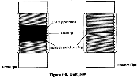
(2) Drive Pipe. Standard drive pipe is furnished in 6- and 8-inch sizes, with the dimensions as shown in Table 9-1. The two ends of the pipe should meet in the center of the coupling, making a butt joint (Figure 9-8). Drive pipe threads are not interchangeable with standard pipe threads.
(3) Drive Clamps. Drive clamps (Figure 9-9) used in driving casing or pipe are attached to the square of the drill stem. When driving the clamps, strike the drive head or coupling at the top of the casing. The stem acts as a guide through the head and furnishes the weight needed for driving.
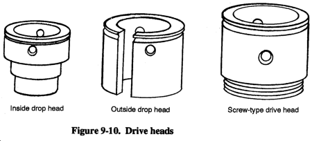
(4) Drive Heads. Drive heads (Figure 9-10) placed on the pipe protect the threads from the driving blows of the drive clamps. The drive heads are put on by unscrewing the bit, slipping the drive head over the drilling stem, and making up the joint again. If you use the screw drive head, make sure you unscrew the drive head from the pipe coupling before pulling the tools from the hole.
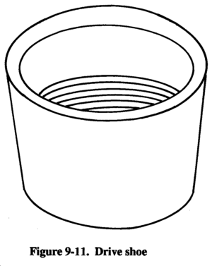
(5) Drive Shoe. Always attach a drive shoe (Figure 9-11) to the lower end of the pipe to prevent the pipe from crumpling while being driven. A drive shoe is threaded to fit the pipe or casing. The inside diameter of the shoe below the shoulder is the same as the inside diameter of the pipe. A drive shoe is forged of high-carbon steel, without welds, and is hardened at the cutting edge to withstand hard driving. Screw the drive shoe tightly to butt the inside shoulder against the end of the pipe.
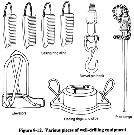
(6) Elevator, Sand Line, and Pin Hook (Figure 9-12). Use casing elevators to handle pipe. The device clamps around the pipe directly under the coupling. You can use the sand line with the elevator for lifting one or two half lengths of pipe. For heavier strings of pipe, use the elevator with the swivel hook attached to the rope socket on the drilling line.
(7) Casing Ring and Slips (Figure 9-12). Use a casing ring to suspend the casing at the ground surface and for pulling pipe from the hole using jacks placed under each side of the casing ring. The rings are made of cast steel and are fitted with handles. All slips are cast steel, with sharp teeth properly hardened.
(8) Pipe Tongs (Figure 9-12). Use chain tongs to tighten the 6- and 8-inch drive pipe. Should the pipe turn in the hole while adding a top length, hold the lower pipe with one tong and tighten the top length with another. If friction in the borehole is enough to hold the pipe while making up top lengths, use both tongs on the top length, opposite each other. Doing so puts an even strain on the pipe, eases the operation, and makes a better joint. Pipe joints must be tight and kept tight while driving pipe; however, keep tong pressure low enough to avoid collapse of the pipe.
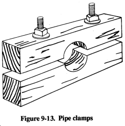
(9) Pipe Clamps (Figure 9-13). You can construct wooden pipe clamps for 6- and 8-inch drive pipe. You can use the clamps to hold the pipe at any position in the hole during drilling operations.
(1) Borehole. Generally, driven wells are started in a hole bored with a hand auger. The diameter of the borehole should be larger than that of the well point, and the borehole should be as deep as the auger will work. In clay soils, boring with an auger is much faster than drilling.
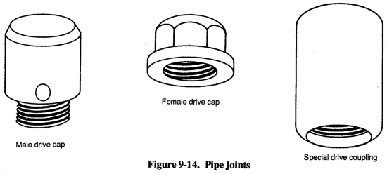
(2) Pipe Joints. Construct pipe joints carefully so that joints are airtight to prevent threads from breaking. If available, use special drive-pipe couplings (Figure 9-14). Screw all joints tightly after cleaning and oiling the threads. Use joint compound to improve airtightness. When transporting and storing joints, you should protect them with caps or couplings. To ensure that joints remain tight, give the pipe a fraction of a turn with a wrench after each blow until the upper pipe joint sets permanently. Do not twist the pipe string while driving.
(3) Pipe. You must keep the well pipe vertical. To check the angle, hold a plumb bob at arm's length from the well pipe and from two directions at right angles to each other. If the pipe is not vertical during the early part of the driving, straighten it by pushing on the pipe while the blows are delivered. If you cannot straighten the pipe, withdrew it and start in a new location.
Use a maul or sledge to strike the drive cap on the well pipe. Hit the drive cap squarely to avoid pipe damage. An alternative to manual driving is a driver that fits over the drive cap. If available, use a pneumatic tamper or sheet pile driver with an air compressor if the pipe is strong. A weak pipe will break at the couplings if you do not use a butt joint.
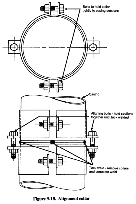
(4) Casing. If you use unthreaded casing, butt-weld the casing lengths. Use an alignment collar for initial tack welding (Figure 9-15). The collar is used to align the pipe or casing to get a straight, tight joint. With the welded casing, you can drive a pipe string and possibly eliminate casing damage. Remove the collars when you complete tack welding.
Another driving method involves a steel driving bar attached to a rope. The bar falls freely inside the pipe and strikes the base of the drive point (Figure 9-16). This method is safest because it does not weaken the pipe.
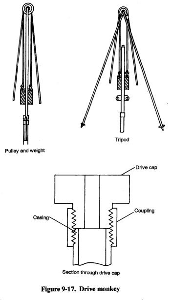
The falling-weight method uses a drive monkey, which is a weight that slides over the pipe (Figure 9-17). A simple arrangement of this method is one in which the monkey slides on a bar supported by the well pipe. Use a drive cap with this arrangement. Another method is to slide the drive monkey over the well pipe to strike the drive clamp that is around the well pipe. You must use a tripod with either method. In soft formations, the descent rate may be 2 or 3 inches per blow. In sand or compact clay, using water in and around the pipe makes driving easier. Extremely compact clay is difficult to penetrate and requires many blows to penetrate a few inches.
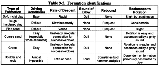
Successful construction of driven wells depends on close observation and correct interpretation of certain work aspects while driving. Interpretation of details such as penetration made with each blow, drop and rebound of the maul or weight, sound of the blow, and resistance of the pipe to rotation helps the well driver to determine the character of the materials being penetrated. Table 9-2 outlines a guide for the identification of the formation being penetrated.
(1) Straight-Pumping Method. You can develop a well with a pitcher-spout hand pump. The pump has a plunger and a check valve arranged so that the check valve trips when you raise the pump handle as high as possible. With this method, you can pump for an extended period before tripping the check valve. Tripping allows water to run back down the well pipe. By applying a heavy suction on the well and tripping the valve, you produce a surging action through the screen openings. The flow reversal, due to the surging, loosens the fine material plugging the screen openings and brings the fine sand and silt into the well point. If you pump continuously for several minutes, these particles may be raised from the well. When the flow is clear, the well is ready for use. Check the pump to ensure that the valves and plunger are free of sand.
(2) Alternative Completion Methods. If you cannot clear all the sediment from the well point by pumping, try any of the following methods:
- Method 1. Lower a series of connected lengths of 3/4-inch pipe into the well with the lower end resting on the sediment in the well point. Clamp the pipe in position and attach a hand pump to the upper end. Run water into the well pipe (not the 3/4-inch pipe) and operate the hand pumps. By steadily pumping, the sediment will be lifted through the 3/4-inch pipe. Continue to lower the 3/4-inch pipe to the sediment level until the well is cleared.
- Method 2. Insert a string of 3/4-inch pipe into the well and fill the well with water. Repeatedly raise and lower the pipe sharply. Hold your thumb over the top of the 3/4-inch pipe during upward movements, and remove your thumb during downward movements. A jet of muddy water is expelled on each downward stroke. When the material loosens and is suspended, you can pump out the muddy water.
- Method 3. Pump water into a string of 3/4-inch pipe that is resting on the sediment to remove the fine material by a jetting action. This procedure requires a large supply of water and a motor-driven or hand-force pump.
a. General. Cable-tool drilling (churn drilling) produces a chopping action. The method and the tool are not expensive, and one person can operate the rig. Cable-tool drilling is a very slow method and is not as widely used as rotary drilling and percussion drilling are used. You can use a cable-tool drill to penetrate rocky soil or moderately hard sedimentary rock. The drill does not require large amounts of drilling fluid. Since the borehole is not full of fluid, you must drive casing as you dig the hole deeper to stabilize the wall.
(1) Rig. The rig consists of a winch with a large wire-rope reel, a walking beam, and a mast. Make sure the wire rope is long enough to reach the anticipated depth. Advance the borehole using a suspended bit for chopping the soil or rock at the bottom of the hole. Thread the wire rope through the walking beam and over a sleeve at the top of the mast. As the walking beam goes down, the bit is lifted; as the walking beam comes up, the bit is dropped. As you dig the borehole, unreel the rope to keep the bit just at the bottom. If the borehole is dry, add water to a few feet off the bottom. As you lift and drop the drill bit, the material is chopped and mixed with the water. After an advance of a few feet, use a bailer to remove the mud.
(2) Tools. A complete set of drilling tools includes the chopping bit and a set of heavy drill jars located above the bit. The stroke of the drill jars is such that when the walking beam is all the way down, the bit is above the bottom of the hole. When the walking beam goes up, the bit drops to the bottom of the hole; as the drill jars close, the bit is impacted. Using a drive barrel and long jars, take a sample from the bottom. The stroke of the long jars is longer than the stroke of the walking beam so that the drive barrel is not lifted off the bottom of the hole while driving with the impact of the jars. Cable-tool drilling involves many cycles. Each cycle involves reeling and unreeling wire rope and is a slower operation compared to a cycle on a rotary rig.
9-5. Augered Wells. You can construct bored wells using hand- or power-driven earth augers. Boring is practical where groundwater can be obtained at shallow depths and when small quantities are needed. Augered boreholes range from 2 to 32 inches in diameter and reach depths of 25 to 50 feet. Engineer troops can construct small-diameter bored wells using organizational equipment.
(1) Hand Auger. These augers consist of a shaft or pipe with a wooden handle at the top and a bit with curved blades at the bottom. The standard engineer auger has fixed blades, but there are bits with blades adaptable to different diameters. Hand augers usually come with several shaft extensions and couplings. To add an extension, remove the handle, couple a section to the pipe, and replace the handle. Hand augers can penetrate clay, silt, and those sands in which an open borehole will stand without caving.
(2) Power Auger. These augers are rotated, raised, and lowered by power-driven mechanisms. The turning force is transmitted to the auger through jointed square or polygonal stems. The power auger issued to engineer troops has a depth limit of about 10 feet. You can use this auger only in areas where the water table is close to the surface.
b. Procedures. To start boring with an auger, force the auger blades into the soil while turning the tool. The auger will cut into the ground at a rate determined by the hardness of the soil. When the space between the blades is full of material, remove the auger and empty it. Repeat the operation until you reach the desired depth.
When constructing bored wells, you may hit small rocks or boulders that will prevent further penetration. When this occurs, lift the auger from the hole; remove the cutting bit, and replace it with a spiral or ram's horn. Lower the tool into the hole and turn the auger clockwise. The spinal should twist around the rock so you can lift the rock to the surface. Remove the spiral, replace it with the regular bit, and continue boring. If you hit a large boulder that you cannot remove with a spiral, abandon the hole and start somewhere else. Wells less than 15 feet deep should not require equipment other than the auger. For deeper wells, use a light tripod with a pulley at the top or a raised platform so you can insert and remove a longer auger rod from the hole without damaging the rod and without unscrewing all pipe sections.
c. Well Completion. If you reach loose sand and gravel, you may not be able to bore below the water table. To overcome this problem, lower a pipe or other casing to the bottom of the hole and continue to remove material while adding weight at the top of the casing to force the pipe down. If you cannot remove material from the hole, use a bailer or sand pump and make the hole deeper. Complete bored wells by installing well screens in the aquifer and developing the well as described in Chapter 7. You may also use drive points (paragraph 9-3a(1)).
If you find groundwater in jointed clay, complete bored wells by lining the hole with clay tile. Use bell- and spigot-type tile and set the tile in the hole with the bell ends down. Pour coarse sand around the tile. You cannot ensure a sanitary well using this completion method. Therefore, use this method when it is the only possible solution.
|
NEWSLETTER
|
| Join the GlobalSecurity.org mailing list |
|
|
|


