CHAPTER 5
BREAKWATERS, ANCHORAGES, AND MOORINGS
BACKGROUND
a. General. Natural processes are continually at work molding coastlines. They may be temporarily eroded by storm waves and later partly or wholly restored by swells. Erosion. and build-up patterns may also occur seasonally. Human settlement along the shore may alter these natural processes. The long-range condition of the beach (whether eroding, stable, or building up) depends on rates of resupply and loss of littoral material. After engineers build ports, they cannot allow the shoreline to migrate either landward or seaward. It is needed to protect shoreside facilities.
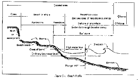
b. Natural protection. Where a sandy beach meets the ocean, it has protection against waves, currents, and storms. The slope of the bottom causes waves to break and dissipate their energy offshore. This process often creates an offshore bar in front of the beach to trip the following waves. The top wave uprush forms a ridge of sand. Beyond this ridge lies the flat berm reached only by storm waves. Figure 5-1 shows a beach profile with its related terminology. Winds blowing inland move sand behind the beach to form dunes. Dunes are the final natural protection line against wave attack, acting as a reservoir for storage of sand against storms. Grass, shrubs, and trees may grow on the dunes as part of a natural levee against sea attack.
c. Functions of shore protection methods. Beaches and dunes may adequately protect shore facilities; however, natural forces sometimes cause erosion as storm waves overlay the beach and damage backshore structures. Man-made construction must then provide additional protection. Generally, measures to stabilize the shore fall into two classes. The first are structures to prevent waves from reaching erodible materials: seawalls, bulkheads, and revetments. Other man-made structures such as groins and jetties may retard littoral drift. The second measure is an artificial supply of sand to make up for a lack of natural sand.
Section I. Breakwaters
a. Definition. A breakwater is a structure protecting a shore area, harbor, anchorage, or basin from waves. It creates calm water and gives protection for safe mooring, operating, and handling of ships, as well as protection for harbor facilities.
b. Types.
(1) Offshore breakwaters. Rubble-mound in the United States.
(2) Shore-connected breakwaters. Rubble-mound, composite, concrete-caisson, sheet-piling cell, crib, or floating. The special advantages of rubble-mound breakwaters should be considered first.
(3) Rubble-mound breakwaters.
(a) Advantages.
* Can be machine constructed and placed.
* Able to rest on any foundation.
* Capable of withstanding breaking waves.
* Resistant to damage from severe storms.
* Allows inexpensive construction and renovation.
(b) Design. Engineers study existing rubble mounds in conditions similar to the proposed breakwater site. They adapt the design according to these principles:
* Waves breach the mound either by overturning the stones or by pulling them down. The slopes of the rock mound absorb the energy of the waves dissipated in shocks, friction, and eddies. The disturbing influence of waves is most keenly felt between the levels of high and low water.
* The mound must have adequate height to provide the desired degree of protection.
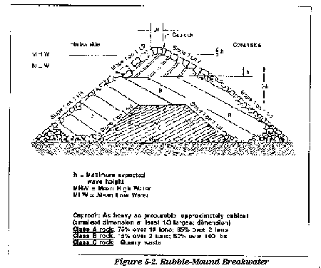
(c) Height determination. The greater the exposure, the higher the crown of the mound should be above the water level. Practical experience determines the economical height to break the wave and prevent it from rolling over the mound. The design should show an initial height above high water level equal to at least two-thirds the maximum expected wave height above mean high water (Figure 5-2). When water levels fluctuate, height increases according to the tide range. If the height proves inadequate, add more materials.
(d) Width determination. The width of the base is influenced by the slopes assumed by the mound under wave action. Engineers must determine the width of the crown or top. When the mound is exposed to ocean storms, a 15- to 20-foot wide top has proven adequate. Severe wave action calls for tops as wide as 70 feet. Constant hydrodynamic action requires the use of heavy material in the mounds. The width should be enough to prevent the mass of water from falling on the harbor side.
(e) Slope determination. Below a certain depth, the mound generally assumes a natural slope ratio that does not exceed 1 vertical on 1 1/4 horizontal. Above this depth the mound is subject to the direct impact of the breaking waves. Below, it is subject to the secondary currents set up when waves meet the breakwater. The slopes above this depth flatten considerably. The surfaces of the mound are protected by carefully laid stones weighing from 10 to 20 tons. Sea slope ratios may vary from 1 vertical on 1 1/2 to 3 horizontal. On the harbor face, a slope ratio of 1 vertical on 1 1/2 to 2 horizontal is usual.
(f) Placement of material. Tests indicate the following cross section for a bottom 60 feet below mean sea level (-60 msl).
* In placing unprotected Class C core material, the top elevation of the section should not exceed -20 msl for waves 7- to 8-feet high. It should not exceed -30 msl for waves 10- to 1l-feet high; -40 msl for waves 15- to 16-feet high; and -50 msl for waves 20- to 21-feet high.
* Class B material should be placed on both landward and seaward slopes while still placing the Class C core material. This should start when the Class C section has been filled to an elevation of -50 msl. Placing Class B material on only one side of the slope is unsafe.
* The top elevation of the Class B section should not exceed -20 msl for waves 15- to 21-feet high. Heavier and larger Class B stone must be placed on a flatter slope than is shown in Figure 5-2.
* For waves 15- to 21-feet high, the seaward slopes of the mound should be on a slope ratio from 1:2 to 1:2-1/2. Use the same design slope given in Figure 5-2. Heavier or larger stone should be used for both Class A and Class B sections. The top elevation of the Class B section should be lowered to about -20 msl. This increases the amount of Class A capstone.
* For 21-foot or larger waves, the ratio of the upper sea-slope should be 1 on 3 with individual surface stones of 15 to 20 tons. The lower slope ratio should be 1 1/2 with Class B rock up to 2 or 3 tons. The interlocking effect of packing or wedging large stones into place increases the strength of the breakwater; so does placing rectangular blocks in close rows. To protect against scour, a riprap belt of Class A material should be placed on a 1:1 slope alongside the seaward toe of the mound. If the outer slope slips, it loses the benefits of packing or wedging stones in the upper face.
* Rubble mounds are exposed mostly at the ends. Therefore, the ends are built higher, wider, and of larger rock to resist the greater wave force. Monolithic blocks of concrete, up to 10 by 40 by 100 feet, are sometimes cast in place on top of such terminals. These large masses hold the rubble mound intact. Where rock is scarce, rubble mounds have been rehabilitated by casting concrete blocks 4 by 8 by 30 feet on top of the sunken mound.
(g) Construction methods. Rubble mounds are built by dumping scows. They use floating cranes for the upper course or dump from rail cars on a track carried on pile bents.
Section II. Wave-Resistant Walls
The upper beach which fronts onshore development requires artificial protection as a the natural protection lost during construction. Engineers have built walls, such as bulkheads, revetments, groins, jetties, and seawalls to serve as substitutes.
BULKHEADS
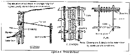
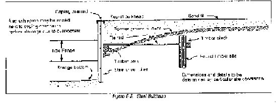
a. General. Bulkheads retain beach-fall material and do not feel severe wave action. Bulkheads may be concrete, steel, or timber (Figures 5-3 through 5-5). Cellular steel sheet pile bulkheads are used where rock is near the surface and where anchored sheet pile bulkheads cannot penetrate adequately. Bulkhead designers should consider the effect of scouring at the base. They may need riprap armoring. Sheet piles must be adequately reinforced for bending moment, soil conditions, hydrostatic pressures, and support points. The first pile must be driven accurately, maintaining good alignment. Design may require a timber aligning frame. The frame has double rows of studs with one or two rows of wales spiked to them. In very plastic soils, it also has diagonal bracing to align the sheet piles.
b. Steel sheet pile. There are two methods of driving steel sheet pile:
(1) Drive a single or a pair of piles simultaneously. This method keeps the driving leads vertical and stable with the hammer centered over the neutral axis of the pile. It requires a firm, level foundation for the pile-driving equipment. Z-piles are driven in pairs.
(2) Assemble all piling in a wall form first, then drive them continuously along the line. This method requires that the piling be set with both axes plumb. Hold the hammer rigid; vibration in the hammer or the pile drives the piles out of alignment.
(3) Short piles driven in soft ground are driven to full depth singly or in pairs. Long piles and hard ground may cause creep. Creep is prevented when--
* Guide waling is set along the sheeting line.
* A pair of sheet piles is driven partway.
* A panel of a dozen single piles or pairs is set in the walings.
* The last pile or pair of piles in the panel is driven partway.
* The piles between the first and last pile or pair of piles are driven to full depth.
* The first pile is driven to full depth. The last pile is driven to two-thirds depth, to act as a guide for the first pile of the next panel.
(4) Soft ground may draw piles down. To counteract draw-down, bolt the piles to stiff waling. A pile that has been drawn down is not jacked up, instead, an additional length is welded onto it.
c. Concrete sheet pile. The foot of a concrete sheet pile is often beveled on one side. This forces the pile against an adjacent pile to maintain contact during driving. Jetting is frequent. If a watertight wall is required, joints are usually grouted after driving. The soil at the bottom of the pile is flushed out with a water-jet pipe long enough to reach the bottom of the pile. A tremie is used to place grout underwater. Concrete is placed in the tremie and deposited. Flexible fillers may be placed in joints at 25- to 50-foot intervals. If a cap is placed on the wall, the flexible joints are continued through the cap.
d. Timber sheet pile. Timber sheet pile bulkheads are used at the inshore end of wharf structures.
REVETMENTS
Revetments protect the shoreline against erosion caused by currents and waves. There are two types of revetments. One is the rigid, cast-in-place concrete type, which gives excellent bank protection. The site must be drained during construction to place the concrete. The other revetment is the flexible or articulated armor-unit type. This revetment also provides excellent bank protection can tolerate minor consolidation or settlement and without structural failure.
GROINS
a. General. A groin is a shore-protection structure that adds to a protective beach or retards erosion of an existing or restored beach. Groins trap material being moved by wave-generated littoral currents. Groins are classified by permeability, height, and length. Common construction materials for groins are stone, concrete, timber, and steel. They can be built of these materials and still be permeable or impermeable; high or low. Asphalt and sand-filled nylon bags have also been used.
b. Timber groins. A common type of timber groin is an impermeable structure composed of sheet piles supported by wales and round piles. Some permeable timber groins have spaces between the sheeting (Figure 5-6).
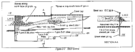
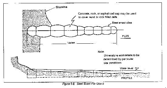
c. Steel groins. A typical design for a cantilever steel sheet pile groin is shown in Figure 5-7. Steel sheet piles have been constructed with straight web, arched web, and Z-piles. The interlocking type joint of steel sheet piles provides a sand-tight connection. The type of sheet pile used depends on the earth forces to be resisted. Cellular steel sheet pile groins serve where adequate pile penetration cannot be obtained for a foundation (Figure 5-8).
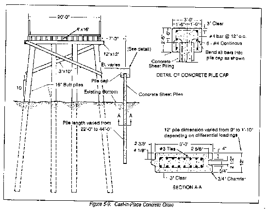
d. Concrete groins. Concrete in groins was previously limited to permeable structures that permitted sand to pass. Figure 5-9 shows a more recent development in concrete groin construction. The groin is an impermeable, prestressed concrete pile structure with a cast-in-place concrete cap.
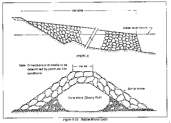
e. Rubble-mound groins. Rubble-mound groins (Figure 5-10) have a core of quarry-run material, including fine material to make them sand-tight. They have a cover layer of armor stone.
f. Normal method of construction. Groins are narrow and stand perpendicular to the shore. They extend from a point landward of predicted shoreline recession, reaching far enough into the water to accomplish their purpose. They vary from less than 100 feet to several hundred feet. Most of the littoral drift moves in the zone landward of the normal breaker zone. Extending a groin of that depth seaward is costly.
JETTIES
a. General. Jetties are designed to control movement and shoaling in channels. Similar to groins, they are usually made of stone, concrete, steel, or timber. Asphalt is sometimes used as a binder.
b. Rubble-mound jetties. Rubble-mound structures are mounds of stones of different sizes and shapes that are either dumped at random or placed in courses. Side slopes and stone sizes are designed to resist wave action. If cheap rock armor units in adequate quantities or size are not available, use concrete armor units. Various shapes of concrete armor have been tested and are available. Figure 5-11 shows quadripod armor units used in jetty construction.
c. Sheet pile jetties. Timber, steel, and concrete sheet piles have been used for jetty construction where wave action is not severe. Cellular steel sheet pile structures require little maintenance. They are suitable for construction in depths to 40 feet on all types of foundations.
d. Normal method of construction. Jetties built on the U. S. open coast are generally rubble-mound structures. In the Great Lakes, engineers have built jetties of steel sheet pile cells, caissons, and cribs, using timber, steel, or concrete. In sheltered areas, they have used a single row of braced and tied wakefield timber piling and steel sheet piling.
SEAWALLS
a. General. A seawall is a vertical, sloping, or stepped wall which protects a shoreline from erosion and other wave action. Seawalls are normally constructed of concrete or stone masonry. However, engineers have had some success with designs using steel, timber, and rubble.
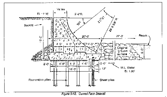
b. Masonry seawalls. Seawalls resist the full force of waves. They are designed as massive gravity-type retaining walls, with additional stability to resist wave and storm action. A curved-face seawall and a combination stepped and curved-face seawall are shown in Figure 5-12. Engineers build these structures to resist high wave action and to reduce scour. Both seawalls have sheet pile cutoff walls at each end. These prevent loss of foundation material by wave scour or storm drainage beneath the wall. The curved-face seawall has an armoring of large rocks at the seaward toe to reduce wave scour. Masonry seawalls are constructed as follows--
(1) Cast-in-place concrete. Concrete is deposited underwater for leveling old footings, stabilizing rock fills, or setting new footings or walls. Bottom-dump buckets with closed tops or tremies make the deposits. During placement, the lower end of the tremie is kept below the surface of the fresh concrete. Footing forms are usually light sheet piling. Wall forms are prefabricated and sunk in place.
(2) Precast concrete blocks. First, engineers cast in place concrete footings with level tops; then they set precast blocks in place. These blocks are provided with rings for crane slings. Blocks are set in contact without mortar below low water. Joints are filled with mortar above low water. Divers may position the blocks underwater. The end joints of the blocks may be battered to improve the contact.
(3) Stone masonry. Stone is sometimes a suitable alternative to concrete masonry.
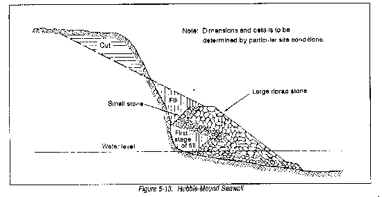
c. Rubble-mound seawalls. The rubble-mound seawall may be a cheaper, more easily designed seawall for the TO. Despite scour of the fronting beach, rock comprising the seawall can settle without causing structural failure. Figure 5-13 shows a rubble-mound seawall using bank material to reduce the stone required.
DESIGN REQUIREMENTS FOR SHORE PROTECTION
a. Structural stability. Structural stability is a function of the configured structural material, loads, and foundation characteristics. Loads present the major unknown to the design engineer. Some of the loads considered in the impact are loads from the waves, static loads from surcharged material, and ice and wind loads.
b. Hydraulic effects. Hydraulic design requires extensive model testing. Engineers must avoid the creation of erosive hydraulic actions resulting from structures they build.
c. Environmental effects. The construction of shore protection facilities may result in changes in erosion and build-up. Design engineers must consider the environmental impact of anticipated changes.
d. Materials availability. Theater of operation supplies are scarce and vary from location to location. Necessary materials not readily available must be transported from nearby locations, increasing both the cost and time factors.
MAINTENANCE AND REPAIR
Engineers should keep shore protection structures in good condition. Repairs of major damage should be completed quickly.
Section III. Anchorage
TWO TYPES OF ANCHORAGE
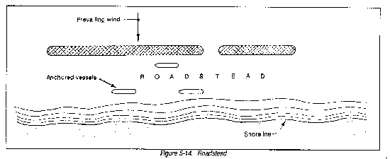
a. Roadstead. Roadsteads (Figure 5-14) are tracts of water near the coastline. They have good holding ground for anchors and some protection from heavy seas. They may be natural or created by placing breakwaters parallel to the coast. The Navy is normally responsible for roadstead layout; however, if Naval support is not available, it may become the responsibility of the port construction unit.
b. Harbor. Sheltered anchorages in a harbor permit access for lighters. They are close enough to lighterage wharves to permit rapid unloading. In some locations, breakwaters and jetties can extend the area already protected by natural land forms.
HARBOR DEPTH
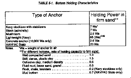
Harbor depth varies. Certain areas are set aside for small craft, and other areas for larger ships. Both small- and large-craft areas must have adequate berthing depth at extreme low water. Failure here makes the installation useless. Bottoms of anchorage areas must be firm enough to hold the pull of a ship's anchor or of buoy moorings. They should be free of hulks or large rocks that foul anchors. When considering anchors, refer to Table 5-1 for bottom holding characteristics.
ONSHORE MOORING ANCHORS
a. Characteristics. Onshore mooring anchors are clusters of piles similar to dolphins. They are driven onshore rather than in the water. They project only a few feet above the surface. The clusters may be much smaller than the clusters needed for similar loads in deep water. Engineers give onshore mooring piles increased horizontal resistance. They tie them back to buried piles or deadmen. The ties between mooring piles and deadmen should be as high on the anchors as possible. But they must not interfere with ship's lines looped over the mooring pile.
b. Uses. Onshore mooring anchors may serve when wharves are not strong or rigid enough to support the stress applied by a moored ship. Onshore mooring anchors also hold floating causeways or floating wharves in place.
ROCK-FILL TIMBER CRIBS
a. Definition. A crib (Figure 5-15) is a rectangular lattice of logs or heavy timbers used to retain rocks or rubble. It furnishes a foundation, retaining wall, or breakwater.
b. Employment. In the past, rock-fill timber cribs served well in the early construction of piers and wharves, particularly in the Great Lakes. Now they are limited to areas where--
(1) Bottom conditions prevent driving piles deep enough to give lateral stability.
(2) Timber lacks adequate length and strength for piling.
(3) Pile-driving equipment is not available.
(4) Skilled labor is unavailable or costly.
c. Construction of cribs. Timber cribs may be built with finished lumber (creosoted, if necessary) or with logs. Logs should be flattened at the point of contact. Cribs are built on shore and floated into position. They are then sunk into position on beds of foundation rock or riprap. The top of the timber crib stops at mean low-water level. It is filled with rock or rubble that will not wash out between the interstices. Above low water, the superstructure walls are usually nonreinforced concrete. The lower section just above the timber has reinforced concrete shells or boxes to hold the remaining concrete in place. Ordinary shattering would let currents and surges of the water wash out the cement and honeycomb mass (nonreinforced) concrete. Freezing and thawing can disintegrate the lower part of crib superstructures made only of mass (nonreinforced) concrete.
d. Disadvantages. Severe settlement occurs if the crib foundation cannot support the applied loads.
Section IV. Landing Ramps
a. Uses. In the early development of a port, engineers may build landing ramps for amphibian vehicles and landing craft.
b. Design.
(1) Most landing craft in the current inventory draw from 3 to 4 feet of water at their bows. Beach gradient must be slight enough not to cause grounding at their sterns. Listed craft may require shore landing ramps that extend out from the shoreline to within 20 feet of where the water is at least 4 feet deep during low tides. The gradient of the face of the beach ramp should be about 3:20, or about 15 percent. Ramp material must--
* Withstand the continuous movement of heavy material-handling equipment while saturated.
* Give traction to vehicles entering or leaving the craft.
* Be flexible enough to prevent serious damage to the landing craft using it.
* Resist scour caused by prop wash of landing craft and by currents parallel to the shoreline.
(2) Crushed rock, gravel, and/or small stones are practical materials for landing ramps. They are placed in layers with the larger armor rock in a 5-foot layer on the bottom. The other, smaller rock is placed on top of the armor rock.
(3) Airfield matting is very good for landing ramps and road networks on beach surfaces. It is versatile, reusable, and easily installed and maintained.
|
NEWSLETTER
|
| Join the GlobalSecurity.org mailing list |
|
|
|


