

CHAPTER 8
PILE WHARVES
Section I. Bearing Piles
PURPOSE
Bearing piles carry superimposed loads, transferring them to the ground as one of the following:
a. End-bearing. A column with the point bearing on rock or firm stratum.
b. Frictional. A column with resistance between the pile and soil into which it is driven. It transmits the load to the lateral soil. Frictional resistance is called skin friction.
TYPES
a. Timber piles.
(1) Uses. Round timber piles are used as bearing piles for timber wharves, fender piles for wharves, and anchor piles for bulkheads. They are also used in pile piers, clusters, and dolphins. Driven flush in clusters, they increase the bearing value of a structure. Timber piles, available in most areas, are easily cut, capped, fastened, and braced.
(2) Characteristics.
(a) The standard timber bearing pile is a straight, firm, solid tree trunk with closely trimmed branches. It should be free of sharp bends, large and loose knots, splits, and decay. It should have a reasonably uniform taper. A straight line from the center of the butt to the center of the tip lies entirely within the pile.
(b) Tip diameters should be 8 to 11 inches for timbers up to 40 feet long and 6 to 8 inches for longer lengths. The diameters of butts should be 12 to 18 inches for timbers up to 40 feet long and 12 to 20 inches for longer lengths.
(3) Life. Timber pile life depends on the species and condition of the wood, pretreatment, and extent of exposure.
(a) Creosoted piles generally last 5 to 10 years in water infested with marine borers. Without marine borers, creosoted piles may last 10 to 20 years when alternately wet and dry. They last indefinitely when continually submerged.
(b) Untreated piles usually last only 3 to 6 months in tropical waters infested by marine borers. Resistant timber species are greenheart or turpentine.
(4) Preparation. The following procedures protect the pile during driving:
(a) For hard-driving, remove 2 to 6 inches of the pile butt after treatment. This particular area becomes saturated with creosote, which penetrates the end grain of the wood easily. The removal of this short-end section transmits the energy of the hammer more readily to the lower sections of the pile. The ends should be treated with cold tar pitch.
(b) Proper fit between the butt of the pile and the driving cap of the hammer protects the pile from damage during hard-driving. The butt of the pile must be square-cut and shaped to fit the contour of the driving cap. Shaping the butt of the pile to fit the cap works best when the point of the pile is a little larger than the cap. The wood will be compressed into the driving cap. Both pointed- and flat-plate shoes (Figure 8-1) are used for round timber piling, but flat plates with square-cut tips are easier to keep in line during driving. Pointed tips add little to the rate of penetration when driving piles into subsurfaces.

(c) If no driving cap is used, or if the pile is crushed or split, the top end of the butt should be beveled and wrapped tightly with 12-gauge steel wire to form a 4-inch band. The wire should be stapled firmly in lace to protect the pile butt during hard-driving. Steel strapping about 1 1/4-inch wide will also provide protection. It should encircle the pile tightly twice, 2 feet from the butt.
b. Steel bearing piles.
(1) Background. In the U. S., steel-pipe piling and steel HP sections (at first H-sections) were used as steel bearing piles because--
* Their manufacture allows long lengths without great handling weights. Engineers have driven unspliced lengths of 127 feet 6 inches, and spliced lengths of 304 feet.
* They penetrate rock and hard materials with the least effort and time.
* Their cross sections are smaller and displace less soil. They are often the only piles that can be driven to the desired penetration without jetting or coring.
* HP steel pales can be driven below the scour line in sand and gravel.
* Penetrations of 10 to 12 feet in hardpan and up to 22 feet in cemented sand and gravel are common.
* HP steel piles can resist large bending moments such as earthquakes.
(2) Commonly used sizes. AFCS designs specify the steel bearing piles most frequently used in military construction. They are the 14-inch HP section steel beam weighing 73 pounds per linear foot, and the 12-inch HP section steel beam weighing 53 pounds per linear foot.
(3) Additional characteristics.
* Steel pipe lengths can be adjusted by cutting, splicing, or welding.
* Steel bearing piles are strong, permitting great lengths and accepting great impact. With firm footing and adequate lateral support, steel bearing piles can support heavy loads.
* Steel bearing piles may be used as friction piles in both compacted or uncompacted sand and gravel.
* Steel bearing piles drive easily into clay. A plain bearing pile will have static resistance greater than the driving resistance indicates. This means skin friction increases after rest. In medium to stiff clay the pile may compact the soil between flanges during driving. The clay may grip the pile and be carried down with it. This has the same effect as using a wider cross section of pile.
c. Concrete bearing piles.
(1) Background. Past TO construction practices have not used concrete bearing piles much. But improvements in pile driving equipment and in pile manufacture, especially in precast and precast-prestressed concrete piling, have made concrete highly suited to TO construction. Important characteristics of concrete piles are as follows:
(2) Advantages.
* Concrete piles carry heavy loads through soft materials to firm, hard layers.
* Concrete piles can be conventionally reinforced and prestressed to resist sizable uplift and bending forces.
* Concrete is not subject to decay or marine borer attack. When properly positioned, it is the most maintenance-free pile material.
* Concrete accepts almost any shape or form desired. It is usually formed into rectangular and octagonal cross sections.
* The large bearing areas of the tips of many types of concrete piles offer an advantage as point-bearing piles.
(3) Disadvantages.
* Concrete piles have poor resistance to lateral forces.
* Spalling of concrete from the surface may expose interior steel to rusting. Rust is especially undesirable in prestressed piles.
* Splicing concrete piles requires cure time.
* When compared to timber or steel piles, concrete piles require larger pile-driving and handling equipment.
(4) Types.
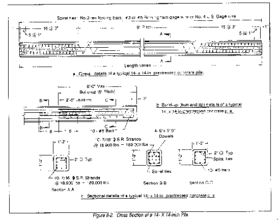
* Precast. Precast concrete piles may be either conventionally reinforced or prestressed. Construction with precast concrete piles specifies precast-prestressed concrete piles. Cross-sections range from 12- by 12-inches to 20- by 20-inches, or equivalent octagonal sections. The 14- by 14-inch cross section (Figure 8-2) is the most common. Problems involved in transporting and handling extremely long members make precast concrete piles longer than 90 to 100 feet uncommon.
* Cast-in-place. Cast-in-place piles are made within a sheet-metal case. The case may or may not be recovered. Uncased cast-in-place piles are common where foundation materials do not allow soil or water to fall into the hole. Here the hole will not change size because of the compressive actions of the soil. Cast-in-place concrete piles are usually reinforced.
d. Composite piles. Composite piles are formed with a combination of two or more materials. Typical examples are--
* Timber or steel in lower sections, and cast-in-place concrete in upper sections.
* Steel pipe piling encasing cast-in-place concrete.
* Steel HP pile sections encased with concrete.
* Timber in lower sections with concrete-fill, thin-gauged, corrugated steel shells in the upper sections. Composites have been used commercially. Construction in the TO limits its use to repairing damaged sections.
SHEET PILES
a. Uses. Sheet piles are special interlocking piles of steel, wood, or concrete. They form a continuous wall which resists horizontal pressure from earth and water and are used to:
* Build cofferdams, which exclude water and earth from an excavation before construction starts.
* Form braces in trench sheathing.
* Form small dams.
* Form cut-off walls beneath water-retaining structures to retard the flow of water.
* Construct bridge piers.
* Construct groins and sea walls.
b. Types.
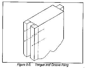
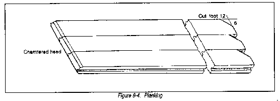
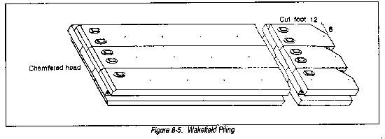
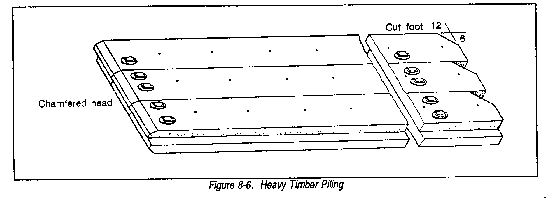
(1) Timber sheet piles. Abundant timber in the TO and a poor supply of steel or concrete allow timber sheet piling for temporary structures. Marine borers and the need for permanent structures make creosoting the timber necessary. Tongue and groove piling of single timbers (Figure 8-3) serves where only earth pressures are involved, such as in excavating a trench above the water table. Larger pressures and work below the water table requires planking (Figure 8-4), wakefields (Figure 8-5), or heavy timber piling (Figure 8-6).
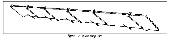
(2) Steel sheet piles. Steel sheet piling is preferred because--
* The interlock (Figure 8-7) on each pile edge guides the pile during driving and can transfer tension from pile to pile.
* Steel sheet piles are strong and easy to drive and align during hard driving.
* The interlocking edge reduces leakage.
* They can be recovered easily for reuse.
(3) Concrete sheet piles. Materials for making concrete are found near most job sites. Concrete sheet piles, nevertheless, are of little use in TO construction. One reason is that pile interlocks cannot transmit tensile forces. Recently, polyethylene interlocks have replaced pile interlocks. Precast-prestressed concrete sheet piles (Figure 8-8) with polyethylene interlocks are capable of transmitting some tensile forces. They also act as a waterstop. Future military construction may adopt this technology since concrete has good structural properties, and it is cheap and widely available.

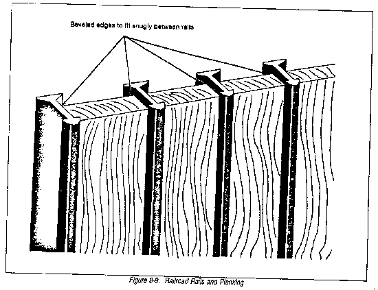
(4) Composite sheet piles. Composite sheet piling is rarely used. Composite forms include railroad rails and planking (Figure 8-9) and one-half sections of steel sheet piles embedded in prestressed concrete sheet-piling for interlocking.
MARINE BORERS
a. General. Some marine animals destroy unprotected or untreated wooden structures in salt water. Creosoting is an effective protection. A few untreated woods, mostly North American types, appear immune to attack. The following conditions favor rapid development of marine life:
* The proper degree of salinity.
* Untreated or unprotected wood between mudline and high waterline.
* Relatively warm waters.
b. Types of borers. The important organisms in a broad classification are:
(1) Mollusks. The teredo, bankia, lyrodus, martesia, hiata, xylophaga, pholas, lithophaga (lithodomus), and zirphae are bivalves, like oysters and clams.
(2) Crustaceans. The limnoria, chelora, and sphaeroma are crustaceans, like crabs and lobsters.
c. Methods of attack. The two types of organisms attack differently. Mollusks drill tiny holes in the wood when they are very young. They grow inside these holes, destroying the wood during their growth. Only inspection of the piling's intersurface can detect mollusk attacks. Crustaceans attack the wood surface, reducing pile diameter as they attack. Crustacean attacks are visible. The teredo, martesia, and limnoria are the most common marine borers.
(1) Teredo. The teredo has a worm-like, slimy gray body with two valves of the shell on the head for boring. During its minute larval stage, the teredo enters the wood. It leaves a tiny hole not larger than a pinhead as the only early sign of infestation. The teredo then tunnels, grows, and lives inside the wood. The interior of the wood becomes a honeycomb of tunnels. In a few months an infested 12-inch pile, which appears sound, may break of its own weight. The teredo prefers warm salt waters. Some have been found in fresh water in India, Australia, and parts of South America. They are active all year in tropical climates. In temperate zones, and even in arctic waters, their numbers may increase suddenly after a rise in water temperatures or salinity.
(2) Martesia. The martesia resembles a clam. Its shell encloses its body entirely. It grows to 2 inches in length and 3/4 inch in diameter. It is highly destructive. Wood disintegrates rapidly under heavy attack. Pile diameter may diminish by 4 inches in a year. Martesia areas are Hawaii, the Philippines, and the Gulf of Mexico.
(3) Limnoria. The limnoria is a tiny distant cousin of the lobster. They destroy piles by gnawing interlacing burrows into the surface, as many as 200 to 300 per square inch. The shallow burrows are 0.05 to 0.025 inch in diameter, seldom over 3/4 inch long. They follow the softer rings, leaving the surface 1/8 to 3/4 inch down a mass of thin walls between burrows that breaks away and exposes a new surface to attack. Limnoria can burrow into soft woods such as pine and spruce to a depth of 1 inch a year. The affected wood presents a spongy appearance. Limnoria work at all levels from the mudline to high water. They are most active below the low-water line, but may attack at the mudline even at 70-foot depths. Occasionally they attack between tide levels. Limnoria avoid hard knots, which are left projecting. They attack piles in other areas after those in the preferred zone become unavailable. If fill is placed around piles up to the low-water line, attack will begin above that point.
d. Methods of protection against marine borers.
(1) Treatment. Marine borers attack wood to obtain cellulose for food. Poisoning is the best protection. Typical treatments are--
* Creosote. Saturating the surface of the wood with creosote is the most common protection against borers. Absorption varies with type of wood, shape of the piece being treated, and intensity of the treatment. From 10 to 24 pounds of creosote per cubic foot of wood are used. All timber piles are creosoted for use in waters where marine borers are active. Thorough creosoting may extend the life of a pile to 20 years or more. Untreated, the wood lasts only a few months. The effectiveness depends on keeping the treated surface unbroken. Do not use timber hooks or pike poles on treated timbers. The surface may need to be punctured or cut when dapping to apply a brace. Protection is restored by adding two or more coats of creosote oil mopped on at temperatures ranging from 175° to 200° C. Creosote is caustic to humans.
* Other chemicals. Copper, sulphate, zinc, and various bituminous and/or asphalt paints are poisonous to borers. These chemicals are, to some degree, soluble in water and can leach out, losing their protective effect.
* Salt/pressure treatment.
(2) Armoring. Successful armoring includes--
* Steel, iron, verified pipe, and concrete cylinder casings.
* Riprap around piling areas to reduce the oxygen content of the water.
* Bark left on the pile as protection against borers. However, bark reduces the bearing capacity of most timber piles.
* Steel and other metal sheathings. Metal must be free of tiny holes.
PILE CAPACITY
a. Bearing pile loads. Bearing piles transmit these superimposed loads to the ground:
* Vertical loads from wharves and vehicles.
* Lateral loads from wind, waves, current, movement of vehicles on the wharf, or the pull of ships at wharf moorings.
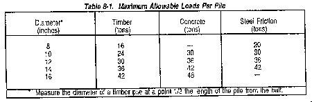
b. Capacity calculation. The safe carrying capacity of a bearing pile depends on its ability to transmit the imposed load to the ground. It does this by either skin friction between the pile and the surrounding soil, or by direct bearing on underlying firm strata. Pile capacity depends on the physical properties of the subsurface soils. Piles for semipermanent wharf structures in the TO are usually limited to the loads in Table 8-1.
PILE BENTS
A pile bent is a support consisting of a single transverse row of bearing piles connected by transverse bracing and a cap (Figure 8-10). The distance between supports holding up a structure is called the span. It is usually covered by stringers and decking.

a. Bracing.
(1) Transverse bracing. Typically 4- by 8- or 4- by 10-inch timbers applied to add stability to a bent. Transverse bracing is applied diagonally (Figure 8-10). It is fastened to each pile with one 3/4-inch bolt. Its vertical spread is from the low-water line to the lower edge of the cap. Large tide ranges, 15 feet or more, require horizontal bracing at low-water level.
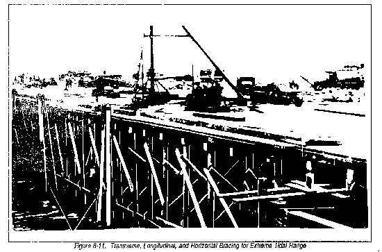
(2) Longitudinal bracing. Adds resistance against lateral forces acting on a wharf structure. Figure 8-11 shows both longitudinal and transverse bracing of a wharf under construction. Engineers use longitudinal bracing between bents of offshore marginal wharves and at bollards on other types of wharves. It is also used on wharves having tidal ranges of more than 15 feet. Sometimes engineers also use horizontal bracing with longitudinal bracing between bents at low water level. Figure 8-11 shows transverse, longitudinal, and horizontal bracing for tidal range over 15 feet.
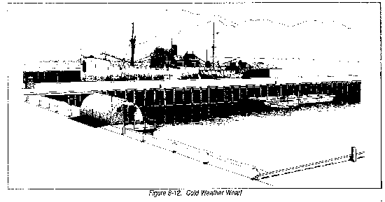
b. Freezing spray. Ice formed on the bracing increases the vertical load on a wharf. This increased load must be lessened or eliminated. Figure 8-12 shows wharves constructed in areas of extreme cold. The bracing is concentrated at the center of the structure and omitted on the outer piles.
c. Pile spacing. The bearing capacity of a friction pile in plastic soil results from transmitting the load to a cone of soil surrounding the pile. If piles are driven close together in soft soil, soil cones overlap. When this happens, the bearing capacity of each pile is lessened. Generally 3 feet is the minimum acceptable spacing. Five or more feet between friction piles allows the piles to act independently.
Section II. Timber Pile Wharves
ADVANTAGES AND DISADVANTAGES
a. Advantages.
* Availability. Timber is readily available in most locations or can be easily transported from nearby areas.
* Good friction pile characteristics.
* Easy to use with TOE equipment.
* Fast construction.
* Lower requirements for highly-skilled labor.
* Cheaper than concrete and steel.
* Flexible and resistant to impact.
b. Disadvantages in container-port construction.
* Impractical in container-port construction due to its limited load-capacity.
* Unavailable in lengths required by container-ports and difficult to splice.
* Susceptible to fire and marine organisms.
* Construction too slow for expedient container-ports, which may be needed in less than 90 days.
c. Summary. Timber construction occurs in break-bulk cargo ports and in most military port construction.
STANDARD PLANS. Army standard structural plans are currently under revision. These plans assume that timber pile wharves are suitable for lighters and break-bulk cargo. Plans assume a uniform live-load of 500 pounds per square foot, side pressure of 1,000 pounds per linear foot, and a Cooper's rating of E-50 where railroads are shown. The designs must be changed to handle the greater loads of container ports. Specific wharf designs and corresponding information still contained in Army manuals are--
a. Types of wharves. Plans and bills of materials (see TM 5-303) are given for--
(1) Rehabilitation of Existing Wharves:
(a) Scheme I, rehabilitation of deep-water piers or wharves, 30 by 500 feet, using timber piling, timber decking, and steel trestling.
(b) Scheme II, rehabilitation of deep-water piers or wharves, 20 by 500 feet, using timber piling, timber cribbing, and steel trestling.
(c) Scheme III, rehabilitation of deep-water piers or wharves, 36 by 500 feet, using steel piling, steel trestling, steel framing, and timber decking.
(d) Scheme IV, rehabilitation of deep-water piers, 36 by 500 feet, using timber piling in concrete-pile boots, timber decking, steel trestling, and combinations of timber and steel framing.
(e) Scheme V, rehabilitation of deep-water piers or wharves, 19 by 500 feet, using timber piling, timber decking, concrete beam support in craters and at quays, steel deck framing, and steel trestling.
(f) Rehabilitation of lighterage wharves, 35 by 500 feet, using timber piling in concrete-pile boots, timber decking, and steel rider caps at quays.
(2) New construction:
(a) A 90- by 500-foot pier with a railroad approach trestle.
(b) A 60- by 500-foot wharf with road and railroad approach trestles.
(c) A 35- by 500-foot lighterage wharf.
b. Details for new construction. Standard designs for the 90- by 500-foot pier and the 60- by 500-foot wharf are given for tides of 5, 15, and 25 feet. For a 35- by 500-foot lighterage wharf, the tide range is 10 feet. Depth at mean high water is 20 feet. Deck elevations for piers and 60- by 500-foot wharves are 6 feet above mean high water; for the lighterage wharf, 5 feet. The designs have timber-pile caps, stringers, curbs, and deck. Fender systems consist of timber piles and chocks. They show longitudinal and transverse bracing details for the different tide ranges and locations. They also show wharf hardware installation details.
c. Adaptability of new construction designs. Standard designs for new construction can be modified. Design engineers can change the size and spacing of timbers to give a structure added strength and rigidity. Pile wharf design is similar to bridge design (in FM 5-312). Wharves, however, must resist much higher lateral pressures.
STRINGER LAYOUTS FOR APPROACH FLARES
a. Pile bents used on approaches to offshore marginal wharves are placed parallel to the shore. Thus, pile caps are parallel and stringers are perpendicular to the shore.
b. Placement of pile bents, caps, and stringers of the wharf proper is opposite that of the approach. Therefore, bents and pile caps are perpendicular and stringers are parallel to the shore.
c. Standard 12- by 12-inch timber pile caps may be used. The portion of the pile bent common to both the wharf proper and the approach (Figure 8-13) is cut off 12 inches lower than the the tops of the piles in other bents.
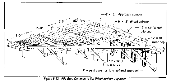
d. The following capping arrangement is used for the bent common to the wharf proper and the approach:
(1) A lower cap of 12-by 12-inch timber is placed on top of the common bent piles.
(2) The pile caps of the wharf proper rest on the lower cap.
(3) Filler blocks (false caps) the same size as the pile caps of the wharf proper are placed on the lower cap between the pile caps of the wharf proper.
Section III. Steel and Concrete Pile Wharves
MILITARY AND COMMERCIAL USES
a. Military uses. The Army currently has no standard design for building new steel or concrete pile wharves. Previous manuals did, however, describe the use of steel piling, trestling, bracing, and limited decking in the rehabilitation of existing piers or wharves. Current military design omits steel and concrete in favor of timber because steel and timber both--
* Require more highly skilled construction personnel.
* Require more time, especially for cast-in-place concrete which requires time for form work as well as curing.
* Require more heavy equipment for positioning and placement.
b. Commercial uses. Commercial port designers have specified steel and concrete pile wharves because both--
* Resist dry rot, marine borers, and termites.
* Can carry heavy loads, including containerized cargo.
*Have lower maintenance costs than timber (especially concrete pile wharves).
* Can be made in any desired shape.
* Are fire-resistant (especially reinforced concrete). Steel is often encased in concrete for protection from high temperatures.
FUTURE USES
a. Rehabilitation. New commercial ports are built to container port specifications. These specifications include either steel or concrete pile wharf construction. It is cheaper to rehabilitate an existing damaged structure than to build a new one. Future engineer construction units will do steel and concrete pile wharf rehabilitation. Steel fabrication and erection methods are described in FM 5-744.
b. New construction. A 30-man commercial construction crew needs nine months to construct a modern (80 by 1,000 feet) steel or concrete pile wharf. This is based on conventional cast-in-place and on-site erection methods. This time factor, even allowing for larger construction crews, restricts TO construction of steel or concrete pile wharves. Steel and concrete will be limited to new nonconventional constructional methods such as--
(1) Steel wharves or piers. Large self-elevating, self-propelled, spud-type barge pier units. Engineers can place these in service quickly.
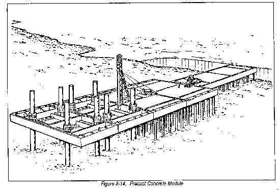
(2) Concrete wharves or piers. Commercial port engineers have prepared designs for precast concrete pier piling, caps, decks, and curbs. Their techniques should decrease time for conventional concrete port construction. These precast elements could also speed construction of new military container ports in the TO. Military engineers can use large precast concrete pier modules. The modules are approximately 35 feet wide, 97.5 feet long, and 12 feet deep (Figure 8-14). Engineers can bring them to the TO and float them into position on barges. They can be temporarily elevate with electrical jacks attached to large caissons. Permanent installation will be on piles driven through prepositioned holes. The piles will be attached to the pier module with an epoxy-resin compound.
Section IV. Construction of Pile Wharves
The Army (AFCS) currently lacks standard plans for building military container piers. Some construction techniques described in this manual will require modification before use.
STRAIGHTENING, CUTTING, CAPPING, AND BRACING PILES
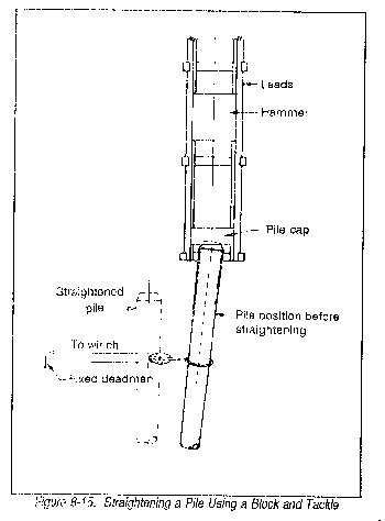
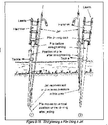
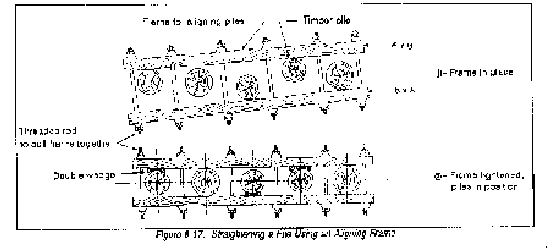
a. Straightening piles. Engineers should straighten piles as soon as they notice any misalignment during the driving. A pile more than a few inches off plumb needs to be straightened. The greater the penetration along the wrong line, the more difficult it is to get the pile back into plumb. Check the alignment by lifting the cap from the pile butt. The pile will rebound laterally if it is not properly aligned with the leads and hammer. The following are ways to realign a pile:
(1) Pull it with a block and tackle (Figure 8-15), using the impact of the hammer to jar the pile back into line.
(2) Use a jet (figure 8-16), either alone or with a block and tackle
(3) Pull it with a tackle and aligning frame (Figure 8-17). The frame may be pulled up when all the piles in the bent are driven.
b. Cutting piles. After piles are driven to the desired penetration, the should be 2 to 3 feet higher than the desired finished elevation. Pile capping should bear evenly on every pile in the bent. Cutting must be accurate. The best way to ensure even cutting is to nail sawing guides across all piles in the bent (Figure 8-18).

c. Capping timber piles. The following are ways of fastening pile capping:
(1) Put the cap in lace after cutting the piles. Bore a hole for a drift pin through the cap into the top of each pile. Then install the drift pins.
(2) Splice a scab across the joints between pile cap timbers. Bolt the scab to each side of the pile cap.
(3) Remove the working platform and the aligning cables or spacing frame. The drift pins will hold the piles in their proper relative positions.
(4) Leave any excess until after capping is placed.
d. Bracing piles. Bents are braced as follows:
(1) Diagonal timbers are bolted to each pile. Bracing runs in one direction on one side of the bent and the opposite direction on the other side.
(2) Piles in a bent may differ considerably in diameter where braced. Large ones may be flattened down with an adz (dapped). Smaller ones may be blocked out with filler pieces. Flexible braces can pull them tight against one another (Figure 8-19).

e. Straightening, cutting, capping, and bracing steel piles (Figure 8-20). Finishing a bent of steel piles follows the same general method as timber piles except--

(1) When bringing the webs of the steel bearing piles parallel to the centerline of the bent, the straightening process may induce twisting.
(2) If the excess length of the pile is cut off, leveling the pile tops justifies any rotting. The piece is welded to the bottom end of another pile.
(3) If the pieces salvaged are so long that the welded joints are below or near the ground, full-perimeter butt welds will give adequate strength. Joints may be above ground level without soil support to resist bending stresses at the weld. When this is true, use web and flange plates as well as butt welding.
LAYOUT FOR POSITIONING PILES
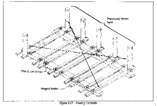
a. Templates. There are several. methods to position piles for driving in water. When a floating pile driver is used, a frame for positioning piles may be fastened to the hull. Sometimes engineers use a floating template (Figure 8-21) to position the piles in each bent. Battens are spaced so that the centerline between them is along the line desired for each pile. As the pile is driven, the larger diameter butt end will not bind on the template and carry it under water. A chain or collar permits the template to rise and fall with the tide. The ends of the battens are hinged. and brought up vertically. The template may be withdrawn from between the bents and floated into position for the next bent. Several templates may be used for a bent; or, if spacing is uniform, a single template may be used and moved for use with the next group.
b. Control of pile positions.
(1) After each bent has been driven, a line is run back from each pile in the outer bent to a corresponding pile several bents shoreward.
(2) The alignment and longitudinal spacing of the out-shore bent is verified.
(3) Any deviation in position of previously driven piles is made up when the template is positioned for the next bent. Piles slightly out of position may be pulled into place later.
PILE-DRIVING PROCEDURES
a. Driving by skid-mounted pile driver. This type of pile driver can be used to drive the piles for an entire structure before the rest of the construction work begins. In general, floating equipment can drive more piles per work-hour because the driver moves relatively easily. Also, as soon as the piles in one bent have been driven, the rig can immediately be repositioned to drive the next bent without waiting until the bent just driven is braced and capped. It is easy to position floating pile drivers, either end-on or side-on, to the pile bent being driven. Thus, batter piles can be driven in any desired direction simply by adjusting the catwalk.
b. Driving by mobile equipment. Mobile pile drivers operate from the deck of the wharf structure. Two procedures move the pile driver forward:
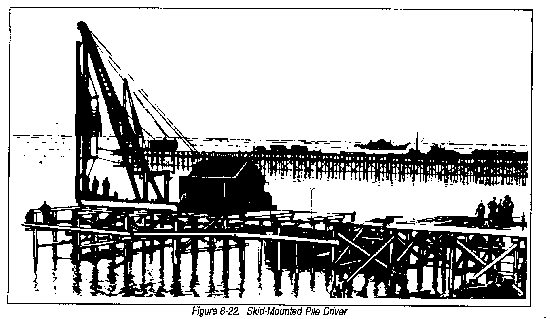
(1) Walking-stringer method. As each bent is driven, the piles are aligned, braced, cut, and capped. Movable stringers are laid ahead of the pile driver onto the bent that was just completed. Movable stringers are made by placing spacer blocks between two or three ordinary stringers and bolting them together. Loose decking is laid on the movable stringers so the driving rig can advance into position to drive the next bent. The advance row or rows of piles are braced, cut, and capped. The pile driver then picks up the temporary stringers behind and swings them into place ahead. Permanent wharf stringers and decking are installed behind the pile driver. A variation of the walking-stringer method is possible with the skid-mounted pile driver (Figure 8-22).
(2) Finish-as-you-go method. This is much the same as the Walking-stringer method. In this method, however, the same crew completes each step, one after the other.
c. Comparison of the two methods.
(1) Walking-stringer.
(a) Advantages. The pile driver is idle less with the movable stringer method. Decking operations are completely separate. Separate crews drive, cut, cap, and deck. Such crews become proficient more rapidly than crews which must do all three tasks.
(b) Disadvantages. This method is more hazardous because the machine is supported by loose stringers and decking. It requires more skill and organization because several operations may be in progress at the same time.
(2) Finish-as-you-go.
(a) Advantages. This method is safer and requires less organization since one operation follows another.
(b) Disadvantages. The driver is idle while each panel is completed. All material must be available to continue construction. Personnel must rotate from job to job.
ERECTION OF STRINGERS AND DECK FOR STEEL PILE WHARVES
a. Steel pile bents. Steel piles in bents must be driven with their webs parallel to the wharf centerline. If not, piles are rotated as they are aligned and capped.
b. Nailers. Nailers are bolted to the wide flange (WF) beam pile cap.
c. Stringers. Establish correct stringer spacing by placing the first stringer on the centerline of the wharf. The centerline is on the nailer of each bent. Timber stringers are toenailed to the nailer with 3/8- by 10-inch spikes at each bearing point. An overlap is provided at the bearing points where stringer ends overlap. Spacer blocks are inserted between parallel stringers atop each nailer.
d. Decking. Standard timber decking consists of 4- by 8-inch planks spiked to each stringer using two 5/16- by 7-inch spikes. They are set with 1/4-inch open joints. Openings between planks greater than 1/4 inch may serve in areas subject to heavy rains.
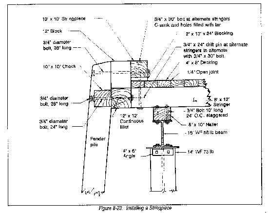
e. Stringpiece. The stringpiece, or curb, is placed on filler blocks spaced at intervals along the edge of the deck. Stringpiece bolts are countersunk and the hole sealed with bituminous material in one of two ways:
(1) When the stringpiece is parallel to the wharf stringers, it is bolted through the blocking, the decking, the stringer end piece, and the nailer.
(2) When the stringpiece is perpendicular to the wharf stringers, it is bolted through the blocking, decking, alternate stringers, and pile cap (Figure 8-23).
CONCRETE SURFACE FOR TIMBER DECKS
a. Pile bents. Steel or timber piles are aligned, braced, and capped as discussed earlier.
b. Stringers. Timber or steel stringers and nailers are installed as discussed earlier.
c. Timber deck. A tight timber deck, consisting of 4- or 6- by 8-inch planking, is spiked to each stringer. All knotholes or openings in the decking wide enough to leak mortar are covered. Green lumber is suitable for the flooring under concrete.
d. Installing mooring hardware. Stringers are reinforced; or, a timber grillwork is installed at bollards or where other heavy items of mooring hardware are to be installed. Mooring hardware may be installed on a timber platform (Figure 8-24) bolted diagonally through decking and stringers. A timber screed (6 by 12 inches) is spiked to the deck between the concrete pour area and the base of the hardware mount. Pile caps are laced on the six piles adjacent to the mooring hardware. Longitudinal cross-bracing is used between the outside bearing piles of at least two pile bents at the bollards.

e. Edging. To retain the concrete, 6- by 12-inch timbers are laid around the edges of the wharf flooring except at scupper openings. They are bolted through the decking, stringer endpiece, or alternate stringers. A 6-inch concrete deck is laid after reinforcement is placed.
f. Reinforcement. To lessen cracking due to temperature changes, the deck is reinforced horizontally in two directions with straight or deformed bars or wire fabric with 12-inch maximum mesh. The bars should not be spaced more than 18 inches apart. The amount of reinforcing steel should not be less than 0.0025 times the cross-sectional area.
g. Joints. Traverse and longitudinal joints are normally provided for concrete expansion and contraction. They are placed no more than 30 feet apart. Vertical grooves may be used to divide the concrete into sections. Use 1- by 6-inch oiled timbers to fill the grooves. As soon as the concrete is set, the timber and all soft concrete are removed and the joint is filled with mastic filler.
h. Scupper openings. To drain water from the deck, a scupper opening is provided. Place 5- by 12-inch timbers 3 feet in length between the 6- by 12-inch edging timbers. Fasten them through the decking and stringers using two bolts. The concrete slab is tapered to 5 inches at the scupper opening.
i. Stringpiece. The stringpiece is fastened to the edging with countersunk bolts. Holes are sealed with asphalt filler.
j. Curing. Concrete must be protected from excessive loss of water until it has achieved about 90 percent of its intended strength. Cover it to prevent excessive evaporation before it dries at the surface or keep it wet. Standard curing practices, applicable to roads and runways, apply to concrete surfaces for timber decks.
CONCRETE PILE WHARVES WITH REINFORCED CONCRETE DECKS
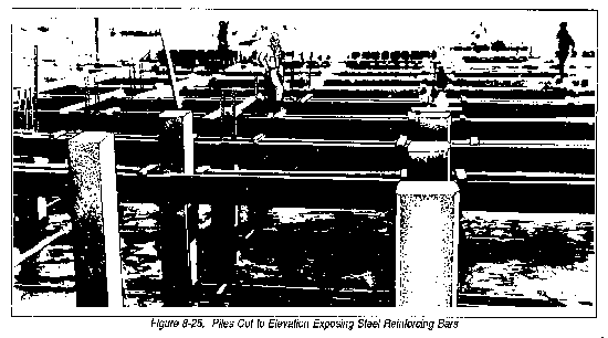
a. Cutting piles. Use pneumatic cutters and drills to cut reinforced concrete piles to the proper elevation. Use acetylene torches to cut the steel reinforcement bars. In Figure 8-25, part of the piles have been cut to elevation, exposing the steel bars which will project into the girder. The falsework for girder, beam, and slab is under construction.
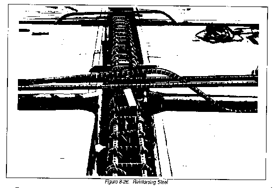
b. Reinforcing steel. Beams and girders are reinforced with longitudinal deformed bars and vertical stirrups. Figure 8-26 shows these in position in the completed deck falsework. To attain continuous slab construction, turn one-half of the slab-reinforcing bars up over the beams. Cut half the bars equal, in length, to the span of the slab plus one-fourth of the span of each adjoining slab. Turn the ends up over the supporting beams from each adjoining slab. The same area of steel is secured over the beam or girder as found in the center of the span. For reinforced concrete work, design drawings should show bending details for the bars. Typical beams and girders should be detailed to show concrete dimensions, required bar lengths, number of turned-up bars, and the number, size, and spacing of stirrups. The construction engineer uses these drawings as a guide for reinforcement bending details. When cutting straight bars to the correct length, he can field-bend them with a bending lever less than 3/4-inch in diameter. Temperature bars are always straight. Deformed bars are generally used for all reinforcement except stirrups, which may be plain bars. Bending stirrups in the field requires detailed drawings. Stirrups are wired to main bars. All reinforcing steel must be accurately located in the forms and held firmly in place before and during pouring. If spacers are not available, block the steel up on cement briquettes and wire it firmly in place.
c. Forms. Engineers should oil forms before placing the concrete so they can be removed and reused. Concrete must be carefully cured. Forms must be kept in place until the concrete has attained enough strength to support itself, and all loads placed on it, before they can be removed or reused. In warm weather, beam strength may develop in 2 or 3 weeks. Low temperatures require more time. Forms should be removed carefully and the concrete examined.
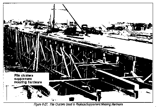
d. Fenders. Concrete wharves are protected with timber fender systems and pile clusters along their faces. Figure 8-27 shows pile clusters several feet above deck elevation that are used to supplement or replace mooring hardware.
e. Mooring hardware. Mooring hardware is fastened to the deck with bolts passing through pipe sleeves set in the concrete. The base of the fitting sits in a recess formed in the deck. After bolting, the fitting is also set in the recess and grouted. This transmits the shear from. the line pull directly to the concrete deck.
INSTALLATION OF STRINGERS AND DECK FOR TIMBER PILE WHARVES
a. Timber pile bents. Timber pile bents are aligned, braced, and capped as previously described.
b. Stringers. The pile cap of each bent is on the centerline of the wharf with the stringers set off from this point. The stringers are toenailed to the pile caps, using two 3/8- by 10-inch spikes at each bearing point. The ends of the stringers are over appeal to provide complete bearing on the pile caps. Spacer blocks between stringers are toenailed with two 60d spikes.
c. Decking. Standard decking consists of 4- by 8-inch Planks spiked to each stringer using two 5/16- by 7-inch spikes, and set with 1/4-inch open joints. Openings between planks greater than 1/4-inch may be used in areas with heavy rains.
d. Stringpieces. The stringpiece or curb (Figure 8-28) is placed on 2- by 10-inch blocking, 24 inches length, spaced on 48-inch centers along the edge of the deck. Stringpiece bolts are countersunk and the holes sealed with bituminous material. The stringpiece is bolted as described earlier for steel pile wharves.

ERECTION OF FENDER SYSTEMS
a. Fender systems consist of fender piles, corner fender pile clusters, chocks, and wales.
(1) Fender piles. Fender piles are driven at a slight batter. The batter is usually 1 to 12 inches along the outside edge of all rows of bearing piles except the inshore sections where ships do not berth.
(2) Chocks and wales.
(a) Chocks are placed between fender piles at the level of the stringpiece or pile cap. Dapping is necessary to firmly seat the chock against the fender pile.
* Timber pile wharves. Each chock is fastened with two bolts through the stringer end piece or pile cap.
* Steel pile wharves. Each chock is bolted to 12- by 12-inch blocks drift pinned to the ends of the stringers or bolted to the ends of the WF pile cap.
(b) Chocks at mean low water level allow additional rigidity to wharf structures. A continuous timber wale, 12- by 12-inches long, is fastened to the back of each fender pile using countersunk bolts. Fender piles are clapped and the chocks and wale bolted together to firmly seat the chocks.
b. Deck reinforcing at corner fenders.
(1) Wood pile wharves. A ten-pile corner fender may reinforce the outer corners of the wharf deck. Prior to setting stringers, wood piles battered inward are driven to support a cap. The cap is set diagonally across each corner and bolted to the bottom face of the other caps. Another piece of cap timber is set to act as a strut between the fender cluster and the diagonal cap. The space between the cluster and the diagonal cap is then floored with two layers of 6-inch thick plank, laid diagonally (and transversal to each other) to fill the space between the cap timbers. Stringers are set close and spike together over the outer half of each corner panel to complete the reinforcement.
(2) Steel pile wharves. In steel pile marginal wharves and in piers with corner fenders, timber reinforces the deck in each corner panel. Wood piles, battered inward, carry a diagonal timber cap bolted to the bottom flanges of the steel pile caps. The diagonal cap is strutted against the fender cluster, and diagonal layers of plank are applied. The stringers are set close and spiked together as described for wood pile wharves.
INSTALLATION AND BRACING OF DOCK HARDWARE
a. Installation of heavy items.
(1) Stringer reinforcement. Install stringer reinforcement and timber grillwork anchorage at the bollards, bitts, heavy cleats, and chocks. Stringers lie close together for reinforcement. They are spiked to each other at each bearing point.
(2) Timber grillwork. Timber grillwork (Figure 8-29) is bolted to the pile caps. Cross timbers and filler timbers are bolted together through all sections of the grillwork.
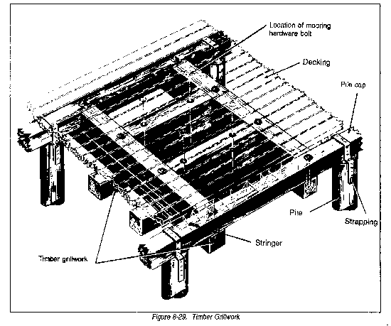
(3) Steel strap. Each pile affected by upward pull on the grillwork is fastened to the pile cap using 3/8-inch steel straps.
(4) Cross bracing. Diagonal bracing, including three bents, is carried from just below the pile caps to the low-water level at each bollard. The cross bracing is bolted to each pile.
(5) Bolts. Bolts for hardware must be long enough to pass through all sections of anchorage.
b. Installation of light items. Light items of mooring hardware, with bolt centers less than 8 inches, such as cleats, chocks, and pad eyes, are bolted through the stringpiece, blocking, decking, and stringer end piece.
PILE CLUSTERS
Pile clusters usually consist of three piles. They may be driven at 50-foot intervals along the face of the wharf to supplement or replace mooring hardware. The clusters are wrapped near the top.
|
NEWSLETTER
|
| Join the GlobalSecurity.org mailing list |
|
|
|