CHAPTER 11
SELF-ELEVATING BARGE PIERS
Section I. DeLong Barges
BACKGROUND
a. The Army has two sizes of self-elevating barges. They are manufactured by the DeLong Corporation and are known as the "A" and "B" units of the DeLong system.
(1) The "A" barge is 300 feet long, 80 feet wide, and 13 feet deep. It is supported by ten 6-foot diameter caissons and ten 500-ton capacity jacks.
(2) The "B" barge is 150 feet long, 60 feet wide, and 10 feet deep. It is supported by six 6-foot diameter caissons and six 500-ton capacity jacks.
(3) In addition, two identical sizes from the Marathon-LeTourneau (M-L) Corporation have been recommended for adoption by the military.
b. Installation and erection procedures for "A" and "B" DeLong barges are outlined in the DeLong jacking systems manual, "Self-Elevating Barge." Therefore, this field manual omits them. It includes all other pertinent information, including fabrication method, design deck loading, supporting systems, operational requirements, past uses and basic considerations in site selection and shore connections.
TYPES
a. Barge. The "A" and "B" DeLong barges are honeycomb-like, welded-steel, box-girder structures consisting of plates and stiffeners. They support a uniform live deck-load of 500 to 600 pounds per square foot. The barges are divided into watertight compartments to maintain safe subdivision in case of towing accidents. Additional watertight compartments provide storage for fresh water and fuel. Each compartment can be entered from the deck through a manhole. The barge has a nonskid deck of 4 by 12 inch wood planking.
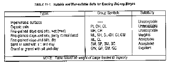
b. Caissons. Each caisson is essentially a welded steel pipe 6 feet in diameter and 140 feet long weighing 80 tons. The wall is normally 1 1/2 inches of American Society for Testing and Materials (ASTM) A-131 steel. To ensure lateral stability, a steel diaphragm is positioned 19 feet from the bottom end of each caisson to develop end bearing strength after sufficient penetration. Another diaphragm is fitted 40 inches from the top end. This allows the caisson to float. The load-carrying capacity of the pier and the depth of penetration of the caissons depend on both the foundation soils and the unbraced length of the caissons. Foundation soils of consolidated clays and nonplastic materials are best. Impenetrable, organic, or highly plastic soils are unsuitable.
c. Air jacks and controls.
(1) Air jacks. An air jack is a barrel-shaped steel cylinder approximately 10 1/2 feet high and 10 feet in diameter. It can raise 500 tons at a nominal rate of 12 feet per hour with a stroke of 12 inches. One jack is provided for each caisson well in the barge unit. The top of the jack is guided by four tie-rods anchored to the deck of the barge. The tie-rods are equally spaced around the air jack. Air jacks are secured to the deck using tie-rods during transit to minimize work at the preparation site.
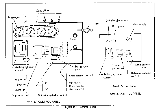
(2) Controls. A master control panel (Figure 11-l) allows controls to operate simultaneously on all caissons. They can be operated individually by smaller control panels (Figure 11-1) connected by flexible hoses to the three-way valves on each jack. The control valves on each panel regulate the functions of the four major jack components as follows:
(a) The jacking control cylinders govern the jacking cylinders around the jack. When the control valve is "on," compressed air is admitted into the cylinder, causing the jack to lift.
(b) The retractor cylinder control regulates two retractor cylinders, spaced 180 degrees apart on the jack. When "on", this valve allows compressed air to enter the retractor cylinders, causing the jack to close.
(c) The upper and lower grippers are in the upper and lower portions of the jack. Each set of grippers has six rubber tubes inside the jack. Two controls regulate their function: the gripper control and the drop caisson control. The gripper control has three positions. In the "lower on" position, the lower grippers inflate and secure the lower portion of the jack to the caisson. The "both on" position secures the entire jack to the caisson. The "upper on" position secures the jack's upper half to the caisson. The "drop caisson" control overrides the gripper control and deflates both upper and lower grippers, allowing the caisson to drop through the jack.
d. Miscellaneous equipment.
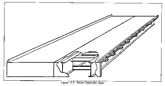
(1) Shore connection span. Shore connection spans (Figure 11-2) are transported to the erection site by the barge units required for the pier or wharf. Each span is 79 feet long by 30 feet wide by 4 1/2 feet high. The span is of girder construction with four 4 l/4-foot girders supporting a 3/8-inch sheet steel deck. It is shipped split lengthwise into 15-foot sections.
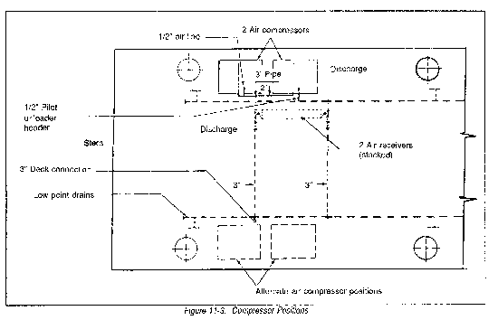
(2) Compressors. Two 350-pound per square inch (psi), 400 cubic foot per minute (cfm) air compressors supply sufficient air pressure to operate and control the pneumatic jacks. The compressors should be secured as shown in Figure 11-3. They should be connected by flexible hose to a receiver tank inlet.
(3) Weld-off rings. Weld-off rings are pieces of steel tubing with a 10 3/4-inch outside diameter, a 1-inch wall thickness, and a 3-inch length. Eight weld-off rings per caisson are provided for semipermanent installations.
(4) Caisson covers. One steel caisson cover protects the cutoff caisson in a semipermanent installation and provides for each caisson-well in the barge unit.
(5) Fenders. The fenders for the "A" and "B" barges are made of 12 by 12 inch timbers and of 6 foot diameter steel hoops. One is provided per caisson.
e. Accessory equipment. Several items of useful equipment not provided with the barge unit include--
(1) Lifting cranes. The cranes listed below are necessary for erecting self-elevating DeLong barges.
(a) The self-elevating barge may be erected with one large barge-mounted crane. The crane should have a boom at least 200 feet long and a 75 percent tipping load rating exceeding 80 tons. The crane should also be capable of handling a boatswain's chair during lift. In addition, a smaller, at least 40-ton, barge-mounted crane may be used to hasten elevation.
(b) The above crane is not a military adopted item of material. Therefore, it may not be available at the site during construction. In this case, it becomes necessary to use at least two smaller barge-mounted cranes. They should each have a 100-ton capacity and 80-foot booms. Such cranes are available for issue from the Naval Ship Systems Command.
(c) Crawler-mounted cranes are useful in small lifting tasks, such as installing fenders and moving compressors and welding machines.
(2) Welding apparatus. If a large barge-mounted crane is not available, or a semipermanent installation is desired, welding equipment is necessary. Both oxyacetylene and electric-arc welding can be used in barge erection.
(a) Oxyacetylene welding equipment may be used. Only fusion welding with a low-carbon or high-strength steel rod is acceptable. A 300° Fahrenheit (F) to 500° F preheat is required with oxyacetylene apparatus.
(b) Electric-arc welding is preferable. It must be metal arc, using reverse polarity and 25-20 or modified 18-8 stainless steel shielded arc rods. No preheat is necessary.
(3) Pile hammer specifications.
(a) Able to work without shore connection.
(b) Six-foot diameter pile capacity.
(c) Rated striking energy of 120,000 foot-pound.
(d) Capable of sixty blows per minute.
(4) Other floating equipment.
(a) A 600-horsepower, 65-foot harbor tug must tow and position the self-elevating barge, especially if crossing open sea. In calm water, a 200-horsepower, 45-foot tug will suffice.
(b) An LCM is useful in positioning and hauling personnel and material between barge and shore.
(c) Various expedient floats, such as small rafts made from 55-gallon drums and small outboard motors, help speed elevation. They help particularly after the barge is jacked clear of the water.
SITE SELECTION FOR DELONG BARGE UNITS
a. Tides. Pier or wharf decks are usually positioned about 5 to 6 feet above mean high water. The mean tide range is the difference in height between mean high and mean low water. It is very important in selecting sites for piers or wharves.
b. Soil (foundation) conditions. Table 11-1 contains guidance in planning and site selection. If the erection site is in CONUS data on offshore subsurface soil conditions is available through the US Geological Survey or from the appropriate Corps of Engineers district office. Outside CONUS, data on subsurface soil conditions may be obtained from local sources, the theater army engineer, or military hydrology and hydrographic teams. All data should be checked by the engineer unit commander.
c. Wave action. Waves under 3 feet high cause little problem when dropping the caissons. Waves from 3 to 5 feet high require care to ensure that the barge stays in position. Waves over 5 feet high require extreme caution to ensure that the barge remains in place with equipment stowed securely. More time is needed to erect these barges in bad weather.
d. Shore accessibility. Ships must be able to dock under all tide conditions. Shore accessibility comes first in site selection. The depth of water at low tide must be at least 50 feet at the construction site. A distance of up to 1,000 feet between the shore and the end of the wharf or pier is desirable. Local bathymetry may help shorten selection time.
e. Approaches. Site selection should also consider onshore road networks. Construction of a new approach from the road net to the shore connection is expensive. However, the approach and the road net should have the following characteristics:
* Straight for at least 150 feet back from the shore connection to avoid vehicles turning onto the connection.
* Less than 10 percent grade at the shore connection.
* At least two lanes (23-foot) travel width (41-foot clearance width), regardless of the connection width.
* Constructed to withstand deterioration in wet weather.
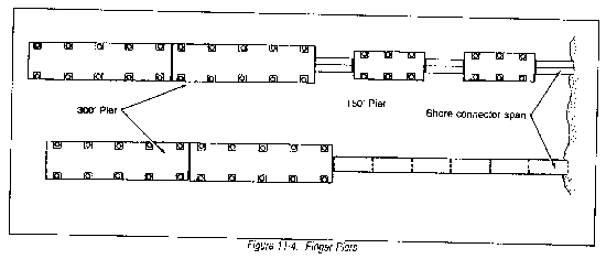
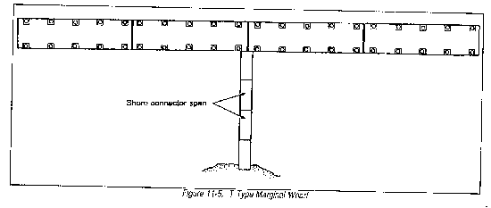
f. Barge arrangements. There are many practical combinations of barges. Figures 11-4 and 11-5 illustrate some of the most promising arrangements.
PAST USES OF DELONG BARGES IN MILITARY CARGO HANDLING
a. Platforms for floating cranes. A large off-load crane mounted on a floating DeLong barge is one of the best methods for offloading container ships under an open sea of 5- to 6-foot waves and 28-knot winds.
b. Construction of general and/or break-bulk cargo piers. The live-load design of DeLong barges allows them to be used as general and/or break-bulk cargo piers. Barges are jacked to the desired elevation. Grippers within the jacks are inflated to 350 psi. The shutoff locks and isolation valves are closed.
c. Construction of container ports. Modified DeLong barges were used as a military container-handling facility in Camh Ranh Bay, Vietnam. The individual barges of this facility accepted the wheel loads of the container gantry crane. This type gantry crane weighs approximately 1,000,000 pounds and has design wheel loads of about 100,000 pounds on 5-foot centers. The gantry at Camh Ranh Bay had a lifting capacity of 27.5 tons.
LIMITS OF DELONG BARGE PIERS IN CONTAINER-PORT CONSTRUCTION
a. Erection time. Each DeLong barge requires from 24 hours to 8 days for installation, depending on terrain and crew efficiency.
b. Structural integrity. DeLong barge pier design takes a 500-to 600-pound per square foot live load. Modern military container ports need a minimum 1,000-pound per square foot live load. Unmodified DeLong barge piers cannot meet modern container port structural requirements.
c. Container-handling capability. If modified DeLong barges are used to construct a temporary installation, cranes must boom up and down to keep from striking individual caissons. The top of the caissons severely affects the off-loading performance of most container-handling cranes. The barge is also jacked to the desired elevation. Grippers within jacks are inflated to 350 psi. Shut-off locks and isolation valves are closed.
d. Relocation. Temporary installations made with DeLong barges are not easily moved. Semipermanent installations are much more difficult because caissons are driven to refusal, cut off, and then welded to the larger gantries. Seldom is it feasible to relocate them.
e. Foundation limitations. Suitable foundations are limited to consolidated clays and nonplastic materials.
f. Shore-connection spans. Shore-connection spans provided with DeLong barge piers do not possess the structural integrity for handling containers.
g. Fender systems. Historically, fender systems provided with DeLong barges have not operated as desired. Damage has occurred to both vessel and pier. Expedient systems using old tires have been more successful in limiting damages.
Section II. Fenders for Barge Units
PURPOSE OF FENDERING
A fender system protects both the vessel and the docking facility from damage caused by contact between the two during docking. Berthing forces are critical because the loading centers on a small part of the facility. However, situations may occur when a ship is retained at a pier under environmental conditions too dangerous to risk berthing. A ship approaching from an angle of 10 degrees may come in contact with as little as 10 to 30 linear feet of the fender. After mooring, the same ship will normally have about one-half its length resting against the fender.
FENDER DESIGN
a. Fender design for marine structures requires working technical knowledge of the--
(1) Size and berthing velocities of ships.
(2) Magnitudes of surge and wave action.
(3) Hull configurations of ships and other vessels using the facility.
(4) Allowable force and deflection of pier or wharf structure.
(5) Soil conditions.
(6) Velocity and direction of winds.
(7) Tidal variation.
(8) Velocity and direction of currents.
(9) Availability and cost of materials, skilled labor, and equipment.
(10) Skill and experience of pilots.
(11) Approach difficulty.
(12) Availability of tugs.
(13) Amount of list that will occur in vessels, especially floating cranes and derricks.
(14) Willingness of operating personnel to maintain mooring lines.
(15) Presence and activity of marine borers and other causes of gradual deterioration.
(16) Facility design and lift.
b. This large number of factors means that a single standard design for all sites is not appropriate.
FORCES FROM WINDS AND CURRENTS
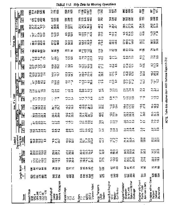
Table 11-2 shows some of the forces from winds and currents acting on ships. This table shows the importance of mooring a ship parallel to strong currents. Wind and current forces are normally static. But when they combine with surge forces, they can impose large roll and surge movements on a vessel. In this situation, a highly resilient fender system may tend to amplify movement of the vessel. Large movements can quickly damage the pier, ship, and fender. Engineers should change the natural frequency of the ship and its mooring system so that it is out of phase with the combined waves and surge. Some remedial steps are:
a. Hold the ship against the pier with a tugboat or constant-tension winch.
b. Relocate or reorient the facility.
c. Install mooring buoys or dolphins outboard of the pier face.
d. Move bow and stern anchors to the outboard sides of the ship during berthing maneuvers.
e. Change to more or less elastic bow, stern, and breasting lines or install elastic snubbers or dampeners in the mooring lines.
f. Add or remove fender units.
g. Place mooring dolphins inboard of the pier face if there is significant pier movement.
RECOMMENDED TECHNIQUES FOR FENDER DESIGN
Fender system designs must conserve energy. The port construction engineer must determine the amount of energy added to the system. Then he must devise a means to absorb the energy within the force and stress limitations of the ship's hull, fender, and pier. One method for devising a fender system to absorb this energy includes--
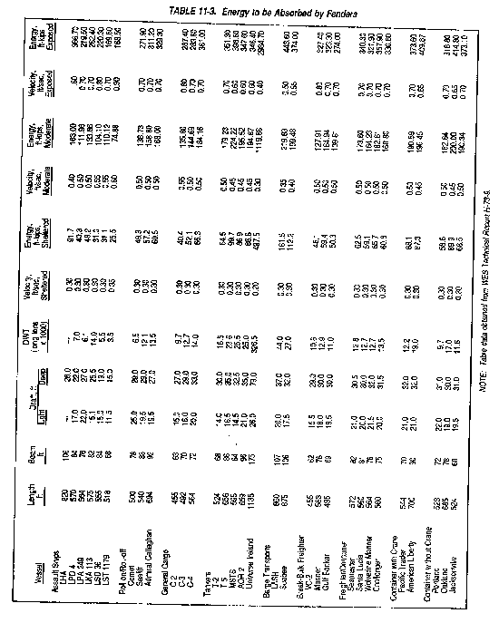
a. Determining the energy delivered to the pier upon initial impact (Table 11-3). The selection of a design vessel should be based on recommendations from the Military Traffic Management and Terminal Service and the Military Sealift Command.
b. Determining the energy that can be absorbed by the pier or wharf and consider distribution of loading. For structures that are linearly elastic, the energy is one-half of the maximum static-load level times the amount of deflection. Allowance must also be made for other vessels moored at the pier. A rigid structure can absorb no energy.
c. Subtracting the energy that the pier will absorb from the effective impact energy of the ship to determine the energy the fender must absorb.
d. Selecting a fender design that can absorb the energy determined above without exceeding the maximum allowable force on the pier. Consider that the thickness of the fender will affect the lifting capacity of the ship's gear and dock cranes.
Section III. Shore Connections
Self-elevating, spud-barge, pier units are usually erected as finger piers and, to a lesser degree, as marginal wharves. Since each must be in water deep enough to accommodate modern shipping, they require shore correctors. The following equipment may satisfy these requirements:
a. DeLong Barge Wharf or Pier. One or more of the DeLong "B" units (150 by 60 by 10 feet) may connect the "A units (300 by 80 by 13 feet) to shore. This method jacks the connecting units to the same elevation as the wharf or pier (5 to 6 feet above mean high water). They would be less susceptible to weather than most floating connections.
b. Military bridging. Several military floating bridge units, including amphibious river crossing equipment, are described in Chapter 10. Because of its rapid installation (FM 5-210) and large loading capacities, this equipment can provide shore connections for most types of offshore ports.
c. Navy pontoon gear. Shore connections for many offshore wharves or piers may be provided with the P-series Navy pontoon gear outlined in Chapter 11.
d. Other connections. Pile-supported approaches or earth and rock fill causeways may be used when shore conditions, time, equipment, and material permit.
|
NEWSLETTER
|
| Join the GlobalSecurity.org mailing list |
|
|
|


