

APPENDIX H
GEOTEXTILE DESIGN
DESIGN GUIDELINES
The widespread acceptance of geotextiles for use in engineering designs has led to a proliferation of geotextile manufacturers and a multitude of geofabrics, each with different engineering characteristics from which to choose. The design guidelines and methodology that follow help you select the right geofabric to meet your construction requirements.
UNPAVED-AGGREGATE DESIGN
Site Reconnaissance
As with any construction project, a site reconnaissance provides insight on construction requirements and potential problems.
Determine Subgrade Soil Type and Strength
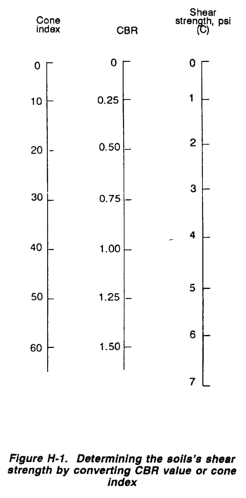
Identify the subgrade soil and determine its strength as outlined in Chapter 9, FM 5-410. If possible, determine the soil's shear strength, C, in psi. If you are unable to determine C, use the nomograph in Figure H-1 to convert CBR value or CI to C.
Determine Permissible Load on the Subgrade Soil
The amount of loading that can be applied without causing the subgrade soil to fail is referred to as the permissible stress, S.
- Permissible subgrade stress without a geotextile:
S = (2.8) C
- Permissible subgrade stress with a geotextile:
S = (5.0) C
Determine Wheel Loads, Contact Pressure, and Contact Area
Estimate wheel loads, contact pressure, and contact-area dimensions from Table H-2. For geotextile design, single and dual wheels are represented as single-wheel loads (L) equal to one-half the axle load, The wheel load exerted by a single wheel is applied at a surface contact pressure (P) equal to the tire inflation pressure. Dual-wheel loads apply a P equal to 75 percent of the tire inflation pressure. Tandem axles exert 20 percent more than their actual weight to the subgrade soil due to overlapping stress from the adjacent axle in the tandem set.
- Estimate the area being loaded (B2):

where B2 = length of one side of the square contact area

Determine Aggregate-Base Thickness
Assuming that wheel loads will be applied over a square area, we can use the Boussinesq theory of load distribution to determine the aggregate-section thickness required to support the design load. Boussinesq theory coefficients are found in Table H-2.

- First, solve for X.
Without a geotextile: 
With a geotextile: 
- Using the calculated values of X and Xgeotextile find the corresponding value of M and from Table H-2.
- Then solve for aggregate-base thickness H and H geotextile.
Without a geotextile: 
With a geotextile: 
The difference between H and H geotextile is the aggregate savings due to the geotextile.
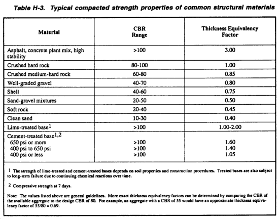
Adjust Aggregate-Section Thickness for Aggregate Quality
The design method is based on the assumption that good-quality aggregate (minimum CBR value of 80) is used. If lower-quality aggregate is used, the aggregate-section thickness must be adjusted.
Table H-3, contains typical compacted strength properties of common structural materials. These values are approximations: use more specific data if it is available. Extract the appropriate thickness equivalent factor from Table H-3, then divide H by that factor to determine the adjusted aggregate-section thickness.
Adjust Aggregate-Base Thickness for Service Life
The design method assumes that the pavement will be subjected to 1,000 passes of the maximum design axle load. If the traffic is greater than 1,000 passes, increase H by the following percentages:
2,000 passes 8%
5,000 passes 19%
10,000 passes 27%
If you anticipate more than 10,000 passes, you need to increase the design thickness by 30 percent and monitor the performance of the road.
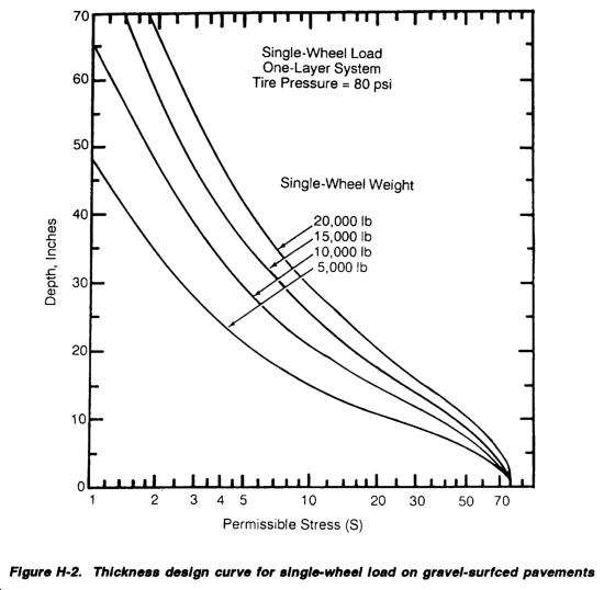
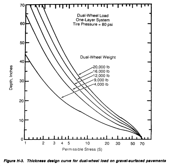
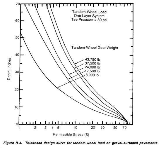
A second method of determining minimum required cover above a subgrade for wheeled vehicles with and without a geotextile requires fewer input parameters. Again, use Figure H-1 to correct CBR or CI values to a C value. Determine the permissible stress on the subgrade soil (S) by multiplying C by 2.8 without a geotextile and by 5.0 with a geotextile. Select the heaviest vehicle using the road and the design vehicle for each wheel-load configuration: single, dual, or tandem. Enter the appropriate graph (see Figures H-2, H-3, or H-4) at S (with and without a geotextile). Round design-vehicle wheel loads to the next higher 5,000-pound increment. Determine the intersection between the appropriate wheel-load curve and S (with and without a geotextile), then read the minimum required thickness on the left axis. Use the greatest thickness values as the design thickness with and without a geotextile. Compare the cost of the material saved with the cost of the geotextile to determine if the use of the geotextile is cost effective.
Up to this point in the geotextile-design process, you have been concerned with general design properties for designing unpaved aggregate roads. Now you must decide which geotextile fabric best meets your project requirements.
TYPES OF GEOTEXTILES
There are two major types of geotextiles: woven and nonwoven. Woven fabrics have filaments woven into a regular, usually rectangular, pattern with fairly even opening spacing and size. Nonwoven fabrics have filaments connected in a method other than weaving, typically needle punching or head bonding at intersection points of the filaments. The pattern and opening spacing and size are irregular in nonwoven fabrics.
Woven fabrics are generally stronger than nonwoven fabrics of the same fabric weight. Woven geotextiles typically reach peak tensile strength at between 5 and 25 percent strain. Nonwoven fabrics have a high elongation of 50 percent or more at maximum strength.
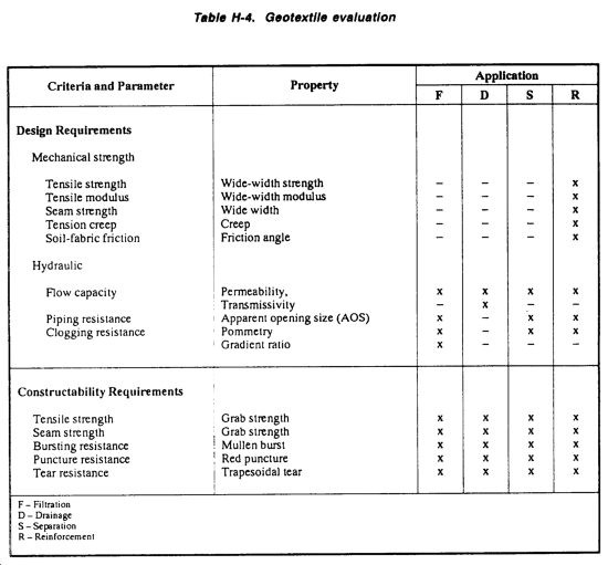
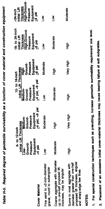
Table H-4, provides information on important criteria and principal properties useful when selecting or specifying a geotextile for a specific application. The type of equipment used to construct a road or airfield pavement structure on top of the geotextile must be considered. Equipment ground pressure (in psi) is an important factor in determining the geotextile fabric thickness; a thicker fabric is necessary to stand up to high equipment ground pressure (see Table H-5).
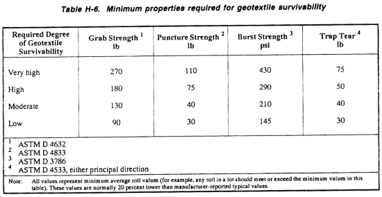
Once the required degree of geotextile survivability is determined, minimum specification requirements can be established based on ASTM standards (see Table H-6). When you have determined the set of testing standards, the geotextile will be required to withstand to meet use and construction requirements, you are ready to either specify a geotextile for ordering or evaluate on-hand stocks.
ROADWAY CONSTRUCTION
There is no singular way to construct roadways with geofabrics. However, there are several applications and general guidelines that can be used.
SITE PREPARATION
Clear, grub, and excavate the site to design grade: fill in ruts and surface irregularities deeper than 3 or 4 inches (see Figure H-5). Compact the subgrade if the soil CBR is greater than 1. The compaction aids in locating unsuitable materials that may damage the fabric. Remove unsuitable materials where practical.
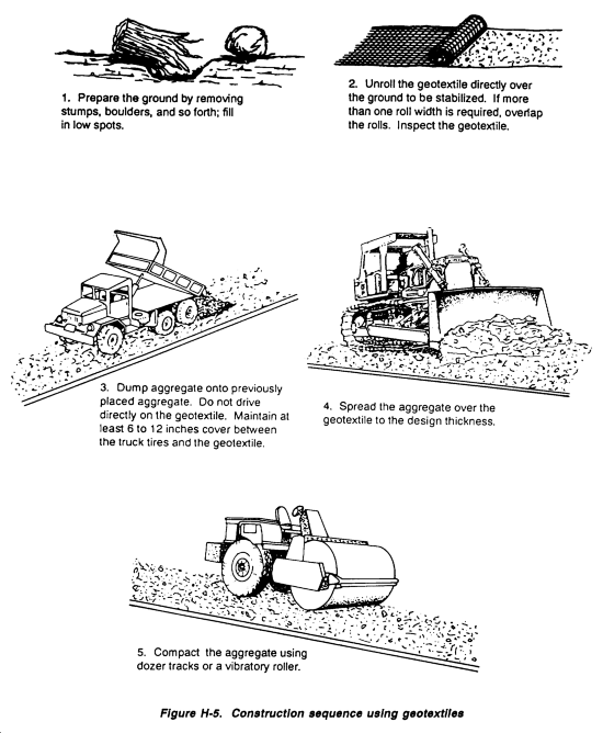
When constructing over extremely soft soils (such as peat bogs), surface materials (such as the root mat) may be advantageous and should be disturbed as little as possible. Use sand or sawdust to cover roots, stumps, or stalks. This cushions the fabric and reduces the potential for fabric puncture. Nonwoven geotextiles are preferred when the soil surface is uneven.
LAYING OF FABRIC
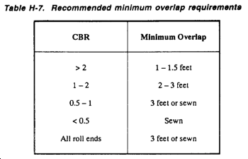
The fabric should be rolled out by hand, ahead of backfilling, directly on the soil subgrade. The fabric is commonly, but not always, laid in the direction of the roadway. Where the subgrade cross section has large areas and leveling is not practical, the fabric may be cut and laid transverse to the roadway. Large wrinkles should be avoided. In the case of wide roads, multiple widths of fabric are laid and overlapped. Lap length normally depends on subgrade strength. Table H-7, provides general guidelines for lap lengths.
LAYING OF BASE
If angular rock is to form the base, it is common to first place a protective layer of 6 to 8 inches of finer material, Base material is then end-dumped directly onto the previously spread load, pushed out over the fabric, and spread from the center using a bulldozer. Vehicles must not be driven directly on the fabric because they might puncture it. Small, tracked bulldozers (with a maximum ground pressure of 2 psi) are commonly used for spreading. The blade is also kept high to avoid driving rock down into the fabric. After spreading, compaction and grading can be carried out with standard compaction equipment. If the roadway has side drains, they are constructed after the pavement.
|
NEWSLETTER
|
| Join the GlobalSecurity.org mailing list |
|
|
|