APPENDIX G
FROST DESIGN FOR ROADS
FROST-AREA CONSIDERATIONS
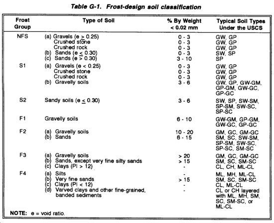
In areas where frost effects have an impact on the design of roads, additional considerations concerning thicknesses and required layers in the road structure must be addressed. The specific areas where frost has an impact on the design are discussed in the following paragraphs; however, a more detailed discussion of frost effects is presented in Special Report 83-27. For frost-design purposes, soils have been divided into seven groups as shown in Table G-1. Only the NFS group is suitable for a base course. NFS, S1, S2, F1, or F2 soils may be used for a subbase course, and any of the six groups may be encountered as subgrade soils. Soils are listed in approximate order of decreasing bearing capability during periods of thaw.
REQUIRED THICKNESS
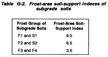
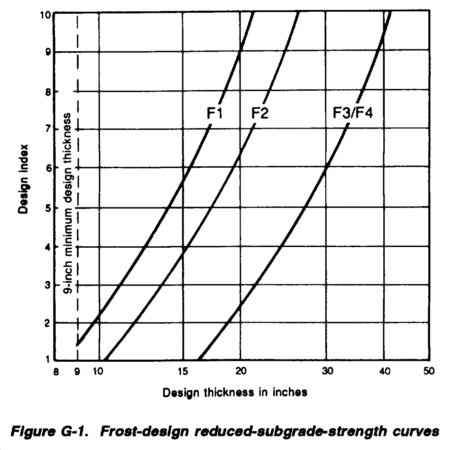
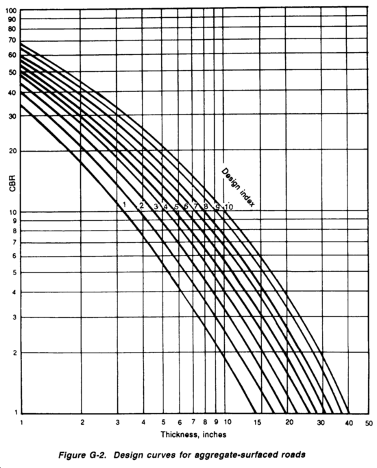
Where frost-susceptible subgrades are encountered, the section thickness required will be determined according to the reduced-subgrade-strength method. The reduced-subgrade-strength method requires the use of frost-area soil-support indexes listed in Table G-2, and strength curves shown in Figure G-1. The required thickness is determined by comparing the natural subgrade CBR to the frost-area soil-support index associated to the relevant first group. If the natural subgrade CBR is less than the frost-area soil-support index then the CBR value governs the design, and the thickness is determined from Figure G-2. If the natural subgrade CBR is greater than the soil-support index, then Figure G-1 is used. The required thickness is determined by entering Figure G-1 at the correct design index, moving horizontally to intersect the relevant frost-group curve, and then moving vertically downward to determine the design thickness in inches.
REQUIRED LAYERS IN A ROAD SECTION
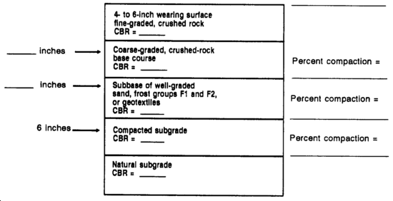
When frost is a consideration, the road section should consist of a series of layers that will ensure the stability of the system, particularly during thaw periods. The layered system in the aggregate fill may consist of a wearing surface of fine-crushed stone, a coarse-graded base course, and a well-graded subbase of sand or gravelly sand as shown in the following example:
|
A wearing surface of fine-graded crushed rock. |
|
A base course of course-graded crushed rock. |
|
A subbase of well-graded sand, frost group soils S1 and S2, or geotextile. |
To ensure the stability of the wearing surface, the width of the base course and subbase should exceed the final desired surface width by a minimum of 1 foot on each side.
WEARING SURFACE
The wearing surface contains fines to provide stability in the aggregate surface. The presence of fines helps the layer's compaction characteristics and helps to provide a relatively smooth riding surface. Its thickness will vary between 4 and 6 inches.
BASE COURSE
The coarse-graded base course is important in providing drainage of the granular fill. It is also important that this material be NFS so that it retains its strength during spring thaw.
SUBBASE
The well-graded sand subbase is used for additional bearing capacity over the frost-susceptible subgrade and as a filter layer between the coarse-graded base course and the subgrade. This process prevents the migration of the subgrade into the voids in the coarser material during periods of reduced subgrade strength. The material must therefore meet standard filter criteria.
The sand subbase must be either NFS, S1, or S2. The filter layer may or may not be necessary depending upon the type of subgrade material. If the subgrade consists principally of gravel or sand, the filter layer may not be necessary and may be replaced by additional base course material, if the gradation of the base course is such that it meets filter criteria. However, for finer-grained soils, the filter layer will be necessary. If a geotextile is used, the sand subbase or filter layer may be omitted because the fabric will be placed directly on the subgrade and will act as a filter. If select materials are used, they must be either NFS, S1, S2, F1, or F2 from Table G-1.
COMPACTION
The subgrade should be compacted to provide uniformity of conditions and a firm working platform for placement and compaction of the subbase. However, compaction of the subgrade will not change its frost-area soil-support index because frost action will cause the subgrade to revert to a weaker state.
THICKNESS OF BASE COURSE AND FILTER LAYER
The relative thicknesses of the base course and filter layer are variable and should be based on the required cover (minimum of 4 inches) and economic considerations.
FROST-AREA DESIGN STEPS
Steps 1 through 5 are the same as for regular aggregate-surfaced roads. (Refer to Chapter 9, Design Steps for Aggregate-Surfaced Roads)
6. Determine the applicable frost group for the subgrade type from Table G-1.
7. Determine the frost-area soil-support index from Table G-2, based on the applicable frost group.
8. Determine the required road-structure thickness. First, compare the natural subgrade CBR to the frost-area soil-support index.
a. If the natural subgrade CBR is less than the frost-area soil-support index, then the CBR value governs the design, and the thickness is determined from Figure G-2, as in nonfrost design.
b. If the natural subgrade CBR is greater than the frost-area soil-support index, then Figure G-1, is used. The required thickness is determined by entering Figure G-1 at the design index, moving horizontally to intersect the frost-group curve, and then moving vertically downward to determine the thickness in inches.
9. Determine the required compaction densities for each layer from Table 9-12.
10. Draw the section of the aggregate road structure.
NOTES:
1. All layer depths should be rounded up to the next full inch for construction purposes.
2. The material should meet gradation requirements.
3. After all possible design sections are determined, the final section used should be determined on the basis of economic analysis.
Example (Frost-Area Design):
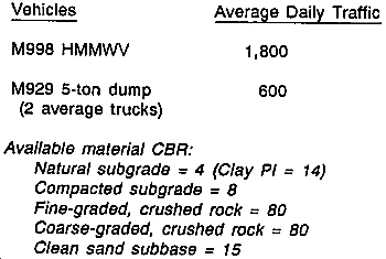
An aggregate-surfaced road in a frost area is to be used for one year. The road will be subject to--
Solution:
1. Number of daily passes = 2,400 (given).
2. Select road class D from Table 9-8, based on average daily traffic of 2,400.
3. Select traffic category IV (Chapter 9), based upon the presence of the 25-percent truck traffic.
4. Select design index of 4 from Table 9-9.
|
5. |
Natural subgrade CBR = 4. |
|
Compacted subgrade CBR = 8 |
6. From Table G-1, the subgrade frost group is F3 based on it being a clay (CL) material.
7. Select frost-area support-index of 3.5 from Table G-1, based on frost group F3.
8. Determine the acquired road-structure thickness.
a. First, look at the required road thickness if it was not designed for frost. In this case, the compact subgrade CBR = 8 is used in Figure G-2. This results in a required total thickness of 6.25 inches, rounding up to 7 inches as shown below.
|
7 Inches crushed rock CBR = 80 |
|
6 Inches compacted subgrade CBR = 8 |
|
Natural subgrade CBR = 4 |
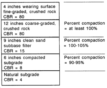
b. Now, design the road for frost. In this case, the natural subgrade CBR = 4, and the frost-area soil-support index = 3.5. Since the natural subgrade CBR is greater than the frost-area soil-support Index, Figure G-1 is used. A design index of 4 is entered into Figure G-1 resulting in a design thickness of 24.5 inches, rounding up to 25 inches. Notice the rather large difference in design thicknesses between frost design and non frost design.
9. Compaction densities for each layer are determined from Table 9-12.
Wearing course: at least 100 percent.
Base course: at least 100 percent.
Subbase course: 100 to 105 percent.
Subgrade: 90 to 95 percent for cohesion soil (PI>5).
10. Draw the section of the frost-area, aggregate road structure.
NOTES:
1. The function of the subbase as a filter layer is not always required, depending upon the subgrade material. In this case, the subgrade is a CL; therefore, it is required.
2. For economy, the thicknesses of the base and subbase courses can be adjusted, so long as the minimum thickness above the CBR= 15 subbase is maintained at 4 inches, as determined from Figure G-2.
3. An overall minimal thickness layer of 4 inches should be maintained.
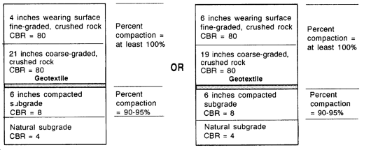
When using a geotextile as a filter layer, the design above could be used by deducting 6 inches of the clean sand subbase and replacing it with a geotextile. The total thickness above the geotextile must be a minimum of 25 inches. Two alternate designs using geotextile are shown below.
|
NEWSLETTER
|
| Join the GlobalSecurity.org mailing list |
|
|
|


