CHAPTER 9
Controls and Instruments
A complex set of controls and instruments monitors the operation of an electric generator set. Equipment operators must understand what these controls and instruments monitor and how they work. Information about many controls and instruments is included in this chapter. Additional information about the controls and instruments for a specific generator set is in the manual issued with the set.
ENGINE CONTROLS
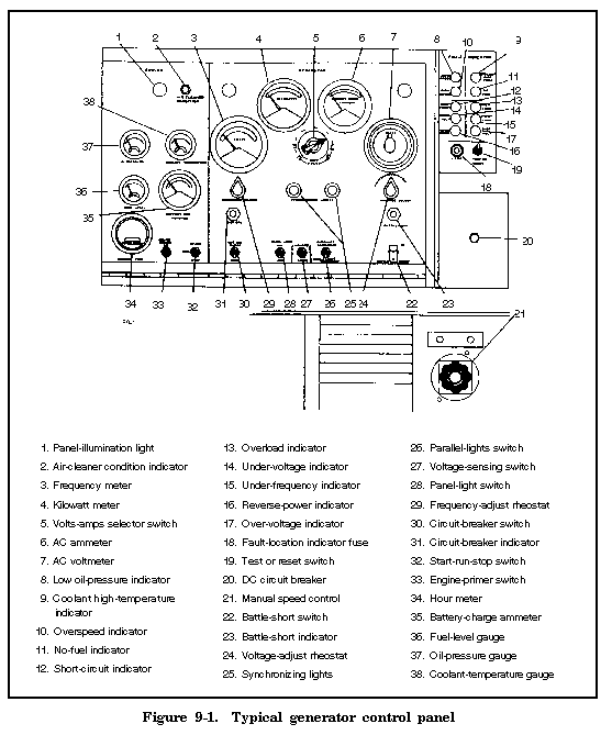
The controls and instruments used to operate a generator set are installed in a control panel similar to the one in Figure 9-1. NOTE: In this chapter, the number in parentheses after the control name corresponds to the callout in Figure 9-1. 
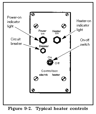
The DC circuit breaker (20) protects DC circuits against shorts and emergency stops. When pressed in the start position, the start-run-stop switch (32) completes the battery circuit to start the motor. The switch is released and returns to the run position after the generator starts. The switch remains in the run position until it is placed in the stop position. The manual speed control (21) regulates the speed of the engine. The heater controls (Figure 9-2) operate the engine's heater. The control set includes a circuit breaker, a heater-on indicator light (press-to-test light), and an on-off switch. The press-to-test light is on when the heater is operating.

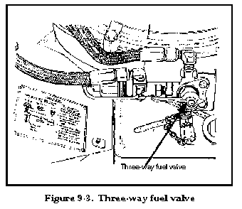
The three-way fuel valve (Figure 9-3) directs the flow of fuel from the source of supply to the fuel pump. The valve has three positions--auxiliary fuel tank, set fuel tank, and off. The first two positions indicate the fuel source. For example, when the valve handle is in the set fuel tank position, fuel is drawn from the tank on the generator set.

SAFETY CONTROLS
Most generator sets have a safety-control system similar to the one in Figure 9-4. The system consists of relays, overspeed safety devices, and pressure-temperature controls.

The generator shuts down when a safety device actuates. Safety devices stop the engine or trip the circuit breaker in cases of overspeeding, low fuel level, low oil pressure, or high coolant temperature. The low oil-pressure indicator (8) illuminates when the oil pressure drops enough to actuate the low oil-pressure safety device. The coolant high-temperature indicator (9) illuminates when the coolant temperature rises enough to actuate the coolant high-temperature safety device. The overspeed indicator (10) illuminates when the engine speed exceeds the rated rpm and the overspeed safety device (Figure 9-5) actuates. The no-fuel indicator (11) illuminates when the fuel in the tank is low enough to actuate the no-fuel protective device.

The battle-short switch (22) permits emergency operation of the generator. This four-pole, on-off switch prevents the generator from starting after a safety device actuates by locking out the starter circuit. It bypasses all protective device circuits except the overspeed and short circuits. During normal operations, the battle-short switch is in the off position.
ENGINE INSTRUMENTS
Several instruments monitor the engine's operation. The oil-pressure gauge (37) indicates the amount of oil pressure maintained in the engine. The coolant-temperature gauge (38) indicates the temperature of the engine coolant. The fuel-level gauge (36) indicates the amount of fuel in the main tank. The battery-charge ammeter (35) indicates the condition of the batteries and the charging system. The hour (time-totalizing) meter (34) indicates the amount of time the generator set has operated.
AC GENERATOR CONTROLS
Several controls monitor the operation of an AC generator. The volts-amps selector switch (5) provides current and voltage readings for each generator phase. A meter is connected to each phase of the main generator. Most switches have six positions that are plainly marked on the face of the selector plate. The phase-selector switch (Figure 9-6) changes the output of a generator to match the voltage and phase requirements of the load. This rotary-type switch is used on generators that produce as much as 10 kilowatts of electricity; changeover boards are used for generators that produce 15 or more kilowatts.

The parallel-lights switch (26) closes the synchronizing-lights circuit in preparation for paralleling two or more power units. It is usually a two-position, rotary or toggle switch. The voltage-adjust rheostat (24) adjusts the value of the output voltage. The rheostat is a small, variable resistor. The circuit-breaker switch (30) disconnects and connects the load lines from the generator set. This switch acts as a main switch and an overload protective device. The circuit breaker automatically disconnects the load from the generator in case of overload, short circuit, or ground on the load lines or within the equipment being powered.
AC GENERATOR METERS
Various meters monitor the output from an AC generator. The AC ammeter (6) indicates the current output of the generator. The output is usually a percentage of the rated load. The AC voltmeter (7) indicates the voltage of the output terminals and, therefore, the voltage output of the generator. The frequency (hertz) meter (3) indicates the line frequency of the generator output in cycles per second. This dial-type meter is used for 50-, 60-, and 400-cycle generators. The kilowatt meter (4) indicates output from the generator. The output reading, in percent of kilowatts, must not exceed the rated capacity of the power plant. The operator must reduce the load if the output reading exceeds the rated capacity of the power plant.
CONVENIENCE OUTLET
The generator contains a 120-volt AC convenience outlet that provides outlets for lights around the generator set. Fuses or a circuit breaker protect the outlet from overloads.
|
NEWSLETTER
|
| Join the GlobalSecurity.org mailing list |
|
|
|

