CHAPTER 6
MGB DESIGN PRO FORMA
(all measurements are in meters)
SS 4 Through 12 Bays
Grid _______________________________
Recon Officer ________________________
Map Ref ____________________________
Unit ____________MLC _______________
1. Measure AR gap A to A' ____________
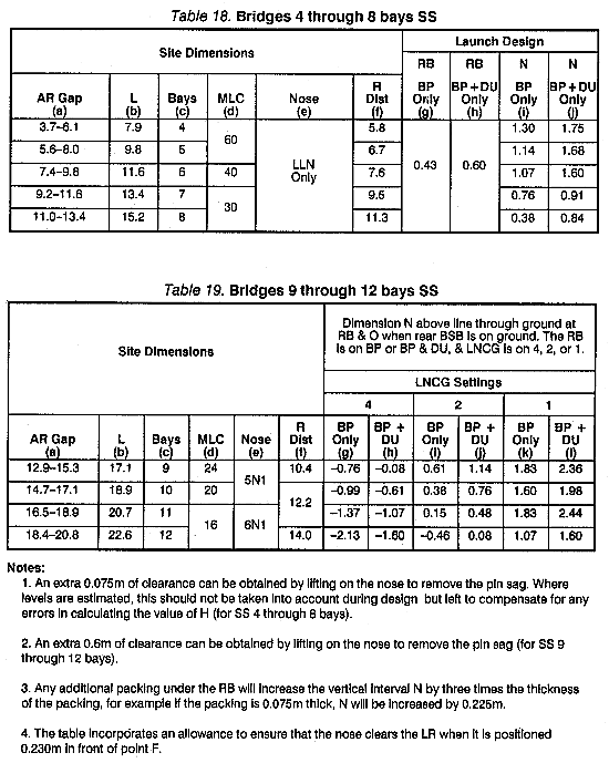
NOTE: Use Tables 18 or 19 to obtain the answers to the following:
2. Select bridge ______________________
3. Bridge length ______________________
4. R distance ________________________
5. Nose construction __________________
6. Key construction points, dimensions, and elevations. Calculate the distance from the RB to the A' peg (X), where --
Push launch:
X = (bridge length + 0.23m) - (AR gap + 0.9m)
Jack launch:
X = (L - 0.23m) - (AR gap + 0.9m)
7. Slope check.
Ensure that the difference in elevation between the F' and F peg does not exceed one-tenth of the actual bridge length. If it does, you will have to crib up, undertake a major construction project, or find another centerline.
8. Calculate H:
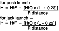
9. Launch design:
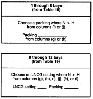
10. Loads required.
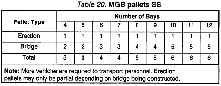
From Table 20, determine the truck and trailer loads required for the bridge.
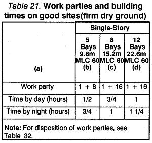
11. From Table 21, extract the following information:
Construction time __________________________
Manpower requirements _____________________
12. Final design:
Bays __________________________________
LNCG setting ___________________________
Packing required _________________________
Bearing: NB ___________FB _______________
Truck and trailer loads _____________________
Manpower required _______________________
Time to construct _________________________
DS 2E + 1 Through 2E + 12 Bays
Grid ____________Recon Officer ____________
Map Ref ________________________________
Unit ____________MLC___________________
1. Measure AR Gap A to A' ________________
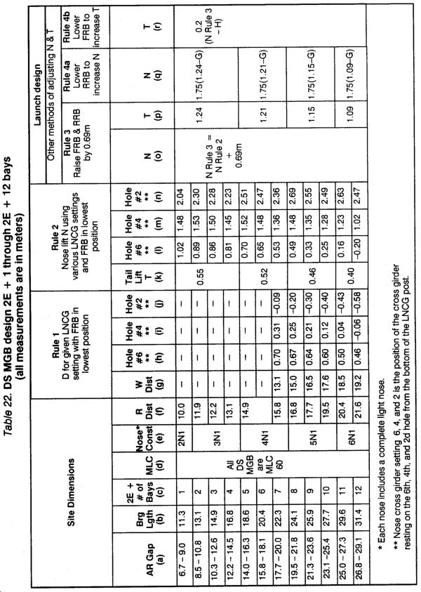
NOTE: Use Table 22 to obtain the answers to the following:
2. Select bridge ____________________________
3. Bridge length ____________________________
4. R distance ______________________________
5. Nose construction ________________________
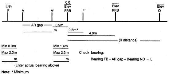
6. Key construction points, dimensions, and elevations (as shown below).
7. Slope check.
Ensure that the difference in elevation between the F and F' pegs does not exceed one-tenth of the total bridge length. If it does, you will have to crib up, undertake a major construction project, or find another centerline.
8. Calculate C, H, and G:


9. RULE 1. (If both bank heights > 0.6m, go to RULE 2.)
Choose an LNCG setting that ensures depth of C > depth of D.
LNCG settings permitted ______ ______ ______
10. RULE 2. LNCG setting to give N > H and T > G.
Choose an LNCG setting so that N > H.
LNCG setting chosen _______________________
NOTE: The setting chosen cannot be lower than that chosen in RULE 1.

11. RULE 3. Raise the FRB and RRB by 0.69m N RULE 3 = N RULE 2 + 0.69m N = ____
Check N Rule 3 > H -- Yes/No
Check T > G Yes/No -- column (p) T = ____
If Yes, design is OK.

12. RULE 4a. Lower RRB
N RULE 4a = N RULE 3 + answer to column (q). Check N > H
13. RULE 4b. Lower FRB
T RULE 4b = T RULE 3 + answer to column (r). Check T > G
14. Loads required.
From Table 23, determine the truck and trailer loads required for the bridge.
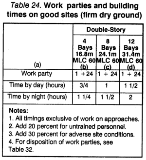
15. From Table 24, extract the following information:
Construction time _______________________
Manpower requirements __________________
16. Final design:
2E + ______________________________bays
LNCG setting _______________________
FRB setting _________________________
RRB setting _________________________
Bearing: NB __________FB ____________
Truck and trailer loads _________________
Manpower required ___________________
Time to construct _____________________
DS 2E + 13 Through 2E + 22 Bays Without LRS
(where water level or any obstructions are at least 2.7m below bank heights)
Grid _______________________
Recon Officer _______________
Map Ref ____________________
Unit ________________________
MLC _______________________
1. Measure AR gap A to A' _____________________
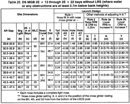
NOTE: Use Table 25 to obtain the answers to the following:
2. Select bridge. 2E + ______________________bays
3. Bridge length ______________________________
4. R distance ________________________________
5. Nose construction __________________________
6. Key construction points, dimensions, and elevations.
7. Slope check.
Ensure that the difference in elevation between the F' and F pegs does not exceed one-tenth of the total bridge length. If it does, you will have to crib up, undertake a major construction project, or find another site.
8. Calculate H and G:

9. RULE 1. LNCG setting to give N > H and T > G.
Choose an LNCG setting so that N > H.
LNCG setting chosen _______________
Then check if T > G
If N > H and/or T > G, go to RULE 2.
10. RULE 2. Raise the CRB and RRB by 0.253m
Check N > H -- Yes/No column (k)
Check T > G -- Yes/No column (l)
If Yes, design is OK.

11. RULE 3a. Lower RRB
N RULE 3a = N RULE 2 + answer to column (m) Check N > H
12. RULE 3b. Lower CRB
T RULE 3b = T RULE 2 + answer to column (n) Check T > G
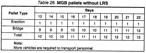
13. Loads required.
From Table 26, determine the truck and trailer loads required for the bridge.
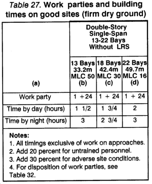
14. From Table 27, extract the following information:
Construction time ________________________
Manpower requirements __________________
15. Final design:
2E + ______________________________ bays
LNCG setting ___________________________
CRB setting _____________________________
RRB setting _____________________________
Bearing: NB _____________FB _____________
Truck and trailer loads _____________________
Manpower required _______________________
Time to construct _________________________
DS 2E + 13 Through 2E + 22 Bays With LRS
(where water level or any obstructions are at least 3.7m below bank heights)
Grid _______________________________
Recon Officer ________________________
Map Ref ____________________________
Unit ________________________________
MLC _______________________________
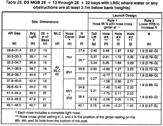
1. Measure AR gap A to A' _________________
NOTE: Use Table 28 to obtain the answers to the following:
2. Select a bridge _________________________
3. Bridge length __________________________
4. R distance ____________________________
5. Nose construction ______________________
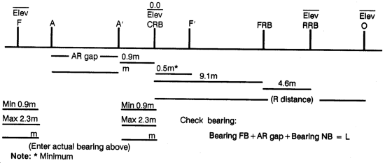
6. Key construction points, dimensions, and elevations.
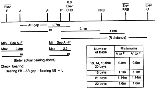
7. Slope check.
Ensure that the difference in elevation between the F' and F peg does not exceed one-twentieth of the total bridge length. If it does, you will have to crib up, undertake a major construction project, or find another centerline.
8. Calculate H and G

9. RULE 1. LNCG setting to give N > H and T > G.
Choose an LNCG setting to give N > H.

10. RULE 2. Lower RRB
N Rule 2 = N RULE 1 + answer to column (k) Check N > H
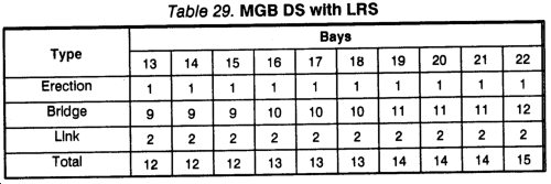
11. Loads required.
From Table 29, determine the truck and trailer loads required for the bridge.
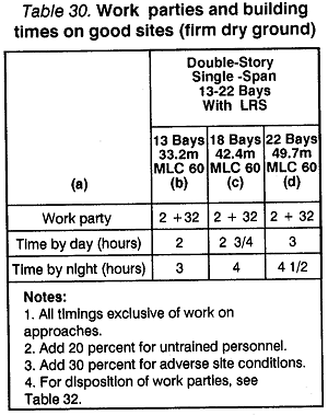
12. From Table 30, extract the following information:
Construction time ______________________________
Manpower requirements _________________________
13. Final design: 2E + _______________________bays
LNCG setting _________________________________
CRB setting __________________________________
RRB setting __________________________________
Bearing: NB ___________________FB ____________
Truck and trailer loads __________________________
Manpower required ____________________________
Time to construct ______________________________
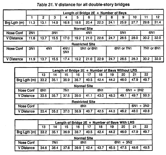
V Distance. The V distance, for delaunching purposes, is the distance from the FRB/CRB to the LRP for DS bridges requiring a launching nose. The V distance must never exceed the distance given in Table 31. Exceeding the V distance may result in failure of the launching nose.

|
NEWSLETTER
|
| Join the GlobalSecurity.org mailing list |
|
|
|


