

CHAPTER 3
MGB 1-12 BAY DS DESIGN
STEP 1. Measure the AR gap (see MGB Design, Step 1).
STEP 2. Select a bridge.
Using column (a) of Table 6, choose a bridge length whose AR gap range brackets the AR gap measured. Always select the smallest range possible to avoid wasting assets. For example, if the AR gap measured 16.2m, choose the AR gap range of 14.0m to 16.3m, even though the range of 15.8m to 18.1m also meets the criteria. Read the bay configuration column (c), and check the MLC of the bridge column (d) to ensure that it meets what is specified by the tasking authority.
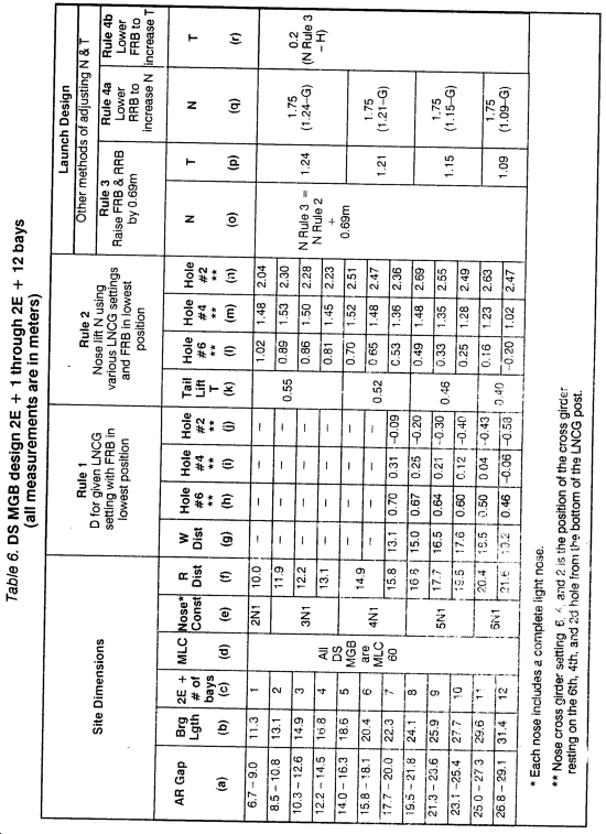
STEP 3. Read the bridge length column (b).
STEP 4. Read and note the R distance column (f).
STEP 5. Read and note the nose construction column (e).
STEP 6. Identify key construction points.
These points are constant for any DS bridge construction up to and including 2E + 12 bays (Figure 5).
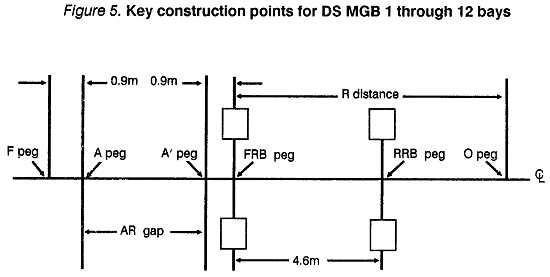
F peg -- Designates the approximate location of the far bank bankseat beam. Initially placed 0.9m from A peg on far bank.
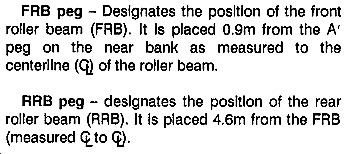
O peg -- Marks the clear distance behind the front roller beam required to construct the bridge. It is positioned by measuring the R distance, Table 6, column (f), behind the FRB peg.
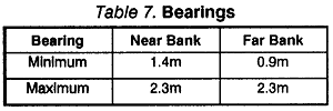
Bearing Check. The minimum/maximum bearings for any DS bridge up to and including 2E + 12 bays are shown in Table 7.
To calculate the actual locations of the F and F' pegs, the following procedure is used:
Near bank bearing = bridge length - (AR gap + 0.9m) where --
- Bridge length is obtained from column (b) of Table 6.
- The AR gap was measured by you in the first step of this design procedure.
- An assumption of 0.9m is made at this point in the calculation sequence because we know that this is the minimum acceptable bearing allowed on the far bank.
If the near bank bearing is within acceptable limits, you do not have to adjust the position of the F peg. Its final position will be the initial value that you assumed of 0.9m from the A peg. The F' peg will be located at a distance equal to the near bank bearing measured from the A' peg on the near bank.
If the near bank bearing is greater than the maximum allowable (2.3m), you must do one of the following:
Move the F peg further away from its present location to a point where the amount of bearing on the near bank is less than or equal to 2.3m, and greater than or equal to 1.4m. This will allow the F' peg to be placed at a suitable distance from the A' peg.
Crib up the near bank end of bridge to where the maximum allowable bearing is not exceeded.
Dig out the soil from the near bank until the maximum allowable bearing is not exceeded.
Physically locate the key construction points (Figure 6) on the ground and take elevations relative to the FRB.
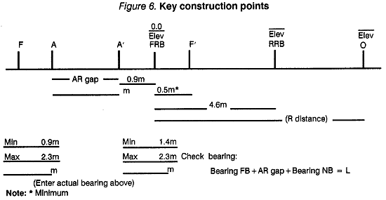
Locate O, RRB, F', FRB, A', A, and F pegs on the ground along the centerline of the bridge.
Estimate elevations of F, RRB, and O pegs relative to the FRB peg. Positive value indicates that a point is above the FRB peg and a negative value indicates that a point is below the FRB peg. The FRB peg will always be 0.0 elevation.
Place the key construction point elevations and distances on the baseline below (Figure 6).
STEP 7. Slope check.
Ensure that the difference in elevation between the F and F' pegs does not exceed one-tenth of the total bridge length. If it does, you are either going to have to crib up, undertake a major construction project, or choose another centerline. Note that the elevation of the F' peg cannot be lower than the elevation of the FRB or the bridge will not receive full bearing. In these cases, the normal procedure is to crib up or fill in until the elevation of the F' peg is at least as high as the FRB. Otherwise, you would have to remove the soil next to the bank to the level of the F' peg. This also applies to the F peg.
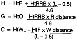
STEP 8.
Calculate the far bank height (H), near bank tail clearance (G) relative to the baseline, and the distance of water below a line joining FRB and F (C) using these formulas:
STEP 9. RULE 1
If both bank heights are greater than 0.6m above the waterline, go to RULE 2. See Table 6.
If either or both bank heights are less than 0.6m from the waterline, choose an LNCG setting from column (h), (i), or (j) so that C is greater than D to avoid immersion in water, and go to RULE 2.
If C is greater than D, go to RULE 2.
If C is not greater than D and the water is not flowing, go to RULE 2.
If C is not greater than D and immersion in water is less than 0.3m and the current speed is less than 5 meters per second (reps), it is not essential to adjust the LNCG setting. Therefore, go to RULE 2.
If C is not greater than D and the current speed is greater than 5 mps, another site must be chosen.
STEP 10. RULE 2
Using the LNCG settings from RULE 1, choose a setting from column (l), (m), or (n) (whichever is allowable from RULE 1) which gives an N greater than H. If none of the choices meet the criterion, choose the highest value available.
Check to see if the T value from column (k) is greater than G. If N is not greater than H, or if T is not greater than G, proceed to RULE 3.
If N is greater than H and T is greater than G, the LNCG setting chosen has adequate nose lift and the bridge selected has adequate tail clearance.
STEP 11. RULE 3
Raise both the FRB and RRB by 0.69m to increase nose clearance (N) and tail clearance (T).
N RULE 3 = N RULE 2 + 0.69m
T RULE 3 = Value obtained from column (p).
If N RULE 3 is not greater than H and T RULE 3 is greater than G, proceed to RULE 4a, column (q)
If N RULE 3 is greater than H and T RULE 3 is not greater than G, proceed to RULE 4b, column (r).
If N RULE 3 is greater than H and T RULE 3 is greater than G, the bridge has adequate nose and tail clearance for launching.
STEP 12. RULE 4a
Lowering the RRB. If there is ample tall clearance, some increase in N can be obtained by keeping the FRB in its highest position and lowering the RRB to its lowest position. The mathematical equation for this process is shown under column (q).
N RULE 4a = N RULE 3 + Value N calculated from the equation shown under column (q).
T RULE 4a = T RULE 3
STEP 13. RULE 4b
Lowering the FRB. If there is ample nose clearance, some increase in T can be obtained by keeping the RRB in its highest position and lowering the FRB to its lowest position. The mathematical equation for this process is shown under column (r).
T RULE 4b = T RULE 3 + Value T calculated from the equation shown under column (r).
N RULE 4b = N RULE 3
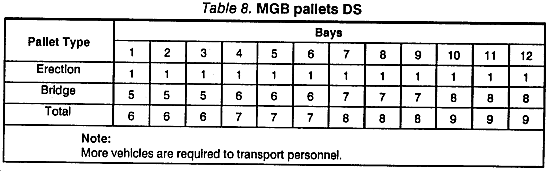
STEP 14. Loads required.
From Table 8, determine the truck and trailer loads required for the bridge.
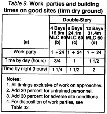
STEP 15. From Table 9, extract the following information:
Construction time______________________
Manpower requirements_________________
STEP 16. Final design:
2E + ______________________________bays
LNCG setting _______________________
FRB setting _________________________
RRB setting _________________________
Bearing: NB ___________ FB __________
Truck and trailer loads _________________
Manpower required ___________________
Time to construct _____________________
|
NEWSLETTER
|
| Join the GlobalSecurity.org mailing list |
|
|
|