

APPENDIX A
RECONNAISSANCE OVERLAYS, SYMBOLS, AND FORMULAS
This appendix provides leaders the necessary data to use overlays, symbols, and formulas in their reconnaissance efforts.
A-1. SYMBOLS
Figure A-1 outlines a variety of symbols that soldiers can use to illustrate reconnaissance data on their overlays. Figure A-2, shows an example of how these graphics are used in the overlay. Figure A-3, shows symbols for various materials, facilities, equipment, and services. (These graphics are adapted from information provided in FM 5-170.)

Figure A-1. Reconnaissance overlay symbols.
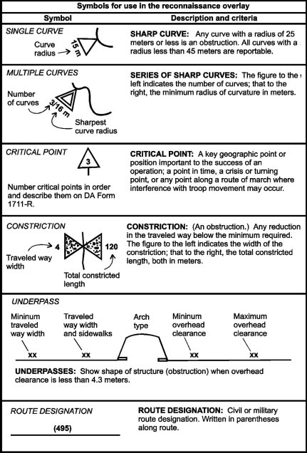
Figure A-1. Reconnaissance overlay symbols (continued).
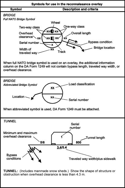
Figure A-1. Reconnaissance overlay symbols (continued).
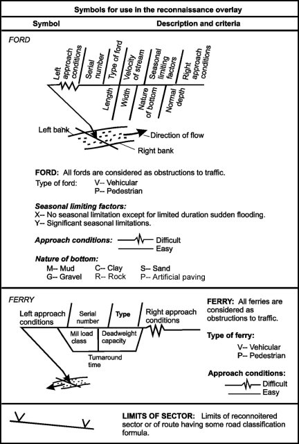
Figure A-1. Reconnaissance overlay symbols (continued).

Figure A-1. Reconnaissance overlay symbols (continued).
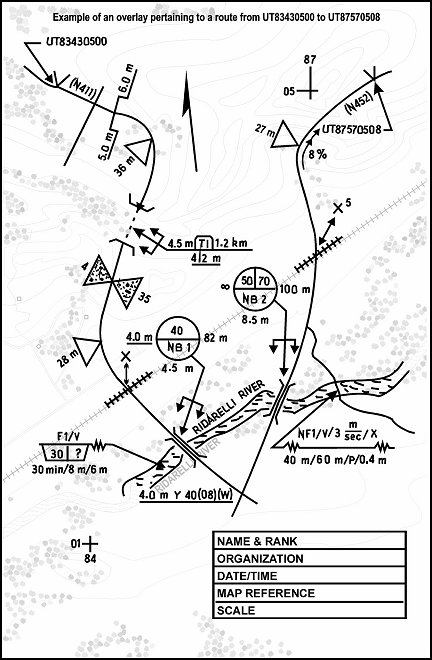
Figure A-2. Example of overlay graphics.
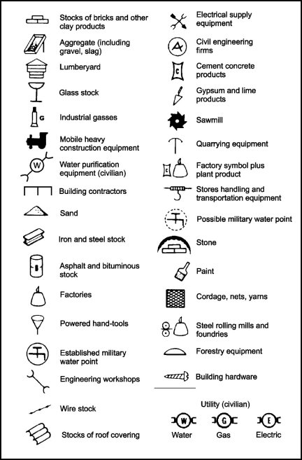
Figure A-3. Material, facility, equipment, and service symbols.
A-2. FORMULAS
This paragraph covers formulas for the reconnaissance platoon to use in water crossing operations and in determining the slope of a road or other piece of terrain. The information is adapted from FM 5-34.
a. Formulas for Water Obstacles.
(1) Width. Scouts can measure the width of a river or stream using one of several available methods:
- Stretching a string or measuring tape across the river or stream.
- Using a map scale.
- Using a compass and the basic mathematical computation illustrated in Figure A-4.
(2) Velocity. Scouts can measure the velocity of the current of a river or stream using the procedures shown in Figure A-5.
b. Slope Computation. To determine the slope of a piece of ground, whether it is an established roadway or a cross-country route, soldiers use a clinometer. If a clinometer is not available, they use the slope computation formula, which requires using one of the following methods to determine horizontal and vertical distances (Figure A-6):
- Compute horizontal and vertical distances based on the map scale and contour differences for the road or terrain.
- Estimate horizontal and vertical distances using pacing and eyesight (hasty method).
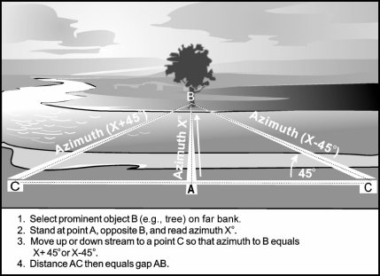
Figure A-4. Measuring stream width with a compass.
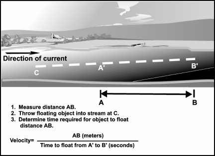
Figure A-5. Measuring stream velocity.

Figure A-6. Slope computation (road gradient).
A-3. CONVERSION TABLES
Soldiers can use the following tables for converting English measurements to their metric equivalents. Table A-1 lists conversions for common distance measurements (inches to centimeters; feet to meters; yards to meters; miles to kilometers). Table A-2, shows conversions of miles per hour to kilometers per hour. Table A-3, refers to field-expedient antenna lengths.

Table A-1. English to metric distance measurement conversions.

Table A-2. Miles per hour to kilometers per hour conversions.
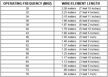
Table A-3. Operating frequency and wire element length.
|
NEWSLETTER
|
| Join the GlobalSecurity.org mailing list |
|
|
|