

Appendix I
Route Classification and Signing System
The military route classification system helps in planning and executing battlefield movements. Military engineers develop route classifications using a route classification formula. This formula consists of a series of numbers and letters that express, in standard sequence, the route width, the route type, the lowest MLC, overhead clearance, obstructions to the traffic flow, and special conditions on a given route. Findings are based on information extracted from route reconnaissance reports.
OVERVIEW
I-1. The first step in completing a route reconnaissance overlay is to understand what information must be included on it. As a minimum, include the following information on the overlay:
The name, rank, and social security number of the person preparing the overlay.
Any remarks necessary to ensure the complete understanding of the information contained on the overlay.
I-2. This appendix focuses on the route classification system and the methods necessary to determine the classification of a road. Refer to FM 5-170 for more information about route classification and reconnaissance.
ROUTE CLASSIFICATION FORMULA
I-3. The route classification is derived from the information gathered during the route reconnaissance. The formula is recorded on the route reconnaissance overlay (Figure I-1) and consists of the following:

Figure I-1. Route Reconnaissance Overlay
I-4. The following are examples of route classification formulas:
6.1/Z/40/
 . A fair-weather route (Z) with a minimum traveled way of 6.1 meters and an MLC of 40. Overhead clearance is unlimited (
 ), and there are no obstructions to traffic flow. This route accommodates both wheeled and tracked, single-flow traffic without obstruction.
 7/Y/50/4.6 (OB) (W). A limited, all-weather route (Y) with a minimum traveled way of 7 meters, an MLC of 50, an overhead clearance of 4.6 meters, and an obstruction. This route width is not suitable for double-flow traffic (wheeled or tracked). This route is subject to regular, recurrent flooding.
I-5. Table I-1, gives route reconnaissance symbols used on a route reconnaissance overlay.
Table I-1. Route Reconnaissance Symbols
|
|
Use this symbol only when the map scale does not permit the use of the full NATO bridge symbol. If this symbol is used, submit DA Form 1249. Draw an arrow to the map location of the bridge. Show the bridge's serial number in the lower portion of the symbol and the MLC for single-flow traffic in the upper portion. If there are separate load classifications for tracked or wheeled vehicles, show the lesser classification. Underline the classification number if the width or overhead clearance is below the minimum standard. |
|
|
|
||
|
|
Use this symbol when the obstacle can be crossed in the immediate vicinity, but some work is necessary to improve the bypass. |
|
|
|
Use this symbol when the obstacle can be crossed in the immediate vicinity by a US 2 1/2-ton truck (or NATO equivalent) without work to improve the bypass. |
|
|
|
Use this symbol when the obstacle can be crossed only by repairing or constructing a feature or by detouring around the obstacle. |
|
|
|
||
|
|
Show roads lined with trees by a single line of circles for deciduous trees and a single line of inverted Vs for evergreen trees. Show woods bordering a road by several rows of circles for deciduous trees and several rows of inverted Vs for evergreen trees. |
|
|
|
Number, in order, and describe critical points on DA Form 1711-R . Use critical points to show the features not adequately covered by other symbols on an overlay. |
|
|
|
Damage or destruction that prevents movement along the route. |
|
|
|
Draw an arrow to the ferry location. The data above the symbols shows, in order, the left approach, the ferry's serial number, the ferry type, and right approach. The data inside the symbol shows, from left to right, the MLC and the dead weight capacity in tons. The number below the symbol shows the turnaround time, in minutes. A question mark indicates unknown information. Show the different approaches by a zigzag line, and show easy approaches by a straight line. |
|
|
|
Draw an arrow to the ford location. The data above the line shows, in order, the left-bank approach, the ford serial number, the ford type, the stream velocity (in meters per second), seasonal limitations, and the right-bank approach. A zigzag line corresponding in position to the shore where the approach is located represents difficult approaches. Straight lines identify an easy approach. The left and right banks are determined by looking downstream. The data below the line shows, in order, the length, the width, the bottom type, and the depth. All measurements are in meters. Seasonal limiting factors: X - none; Bottom type: M - mud; C - clay, |
|
|
|
Indicate wheeled vehicles in the upper third of the symbol with the two-way wheeled classification on the left and the one-way wheeled classification on the right. Show tracked vehicles in the center third of the symbol with the two-way tracked classification on the left and the one-way tracked classification on the right. Place the bridge serial number in the lower third of the symbol. Draw an arrow to the bridge location and show the bypass conditions on the arrow shaft. Place the traveled-way width below the symbol, the overhead clearance to the left of the symbol, and the overall length to the right of the symbol. |
|
|
|
Show the actual percent of grade to the right of the symbol. Any grade of 7 percent or more is an obstruction. Include the obstruction in the route classification formula. Arrows should point uphill. The length of the arrow represents the length of the grade if the map scale permits. |
|
|
|
Use a broken line, and identify the route by an even number. |
|
|
|
Show the beginning and ending of a reconnoitered section of a route or road with this symbol. |
|
|
|
||
|
|
Place the center of the symbol over the location of the blocked part of the route. Use parallel broken lines for a proposed block, parallel lines for a prepared but passable block, and crossed lines for a completed block. |
|
|
|
||
|
|
||
|
|
Use this symbol to show a level crossing where passing trains would interrupt the traffic flow. If there is a power line present, show its height, in meters, from the ground. Underline the overhead clearance if it is less than 4.3 meters. |
|
|
|
Place RL above the symbol to indicate a railway bridge. At the left of the symbol, show the overhead clearance. Show the overall length of the bridge on the right of the symbol. Indicate the traveled-way width below the symbol, and underline it if it is below standard for the classification. Inside the symbol, show the bridge classification in the upper half. If the class is different for single- and double-flow traffic, show single flow on the left and double flow on the right. Place the railway bridge serial number in the lower half of the symbol. Draw an arrow to the bridge location. On the arrow shaft, indicate the ease of adapting the bridge for road vehicle use. A zigzag line means it would be difficult to adapt, and a straight line means it would be easy to adapt. Place the bypass symbol on the arrow shaft to indicate the bypass conditions. |
|
|
|
Express the formula in the order of the route width, the route type, MLC, minimum clearance, obstructions (if present), and special conditions. All measurements are in meters. |
|
|
|
Write the number of curves and the radius of the sharpest curve of the series to the outside of the triangle. |
|
|
|
Point the vertex of the triangle to the curve location and indicate the radius of the curve, in meters, outside the triangle. A curve of 45 meters or less must be reported on the overlay, and a curve of 25 meters or less is an obstacle. |
|
|
|
||
|
|
||
|
|
Draw an arrow to the tunnel location. Place the bypass condition symbol on the arrow. Show the minimum and maximum overhead clearances to the left of the symbol, the tunnel serial number inside the symbol, and the total tunnel length to the right of the symbol. Below the symbol, show the traveled-way width. If sidewalks are present, follow with a slash and the total traveled way, including sidewalks. Underline the traveled way if the road entering the tunnel is wider than the traveled way of the tunnel. Use a question mark to show unknown information. |
|
28. Turnout; |
|
Use this symbol to show the possibility of driving off the road. Draw the arrow in the direction of the turnout (right or left of the road). For wheeled vehicles, draw a small circle on the shaft of the arrow. For tracked vehicles, draw a small square on the shaft of the arrow and place the length of the turnout, in meters, at the tip of the arrow. When the turnout is longer than 1 kilometer, use double arrows. |
|
|
Draw the symbol over the road. Place the width of the traveled way, in meters, to the left of the symbol. If sidewalks are present, follow the traveled-way width with a slash and the total width, including sidewalks. Underline the traveled-way width if the road entering the underpass is wider than the underpass traveled way. Show the overhead clearance, in meters, to the right of the symbol. Show both minimum and maximum overhead clearances, if different. |
|
|
|
Use a question mark with almost any symbol when information required for the symbol is unknown or doubtful. |
|
|
|
The minimum width is to the left of the symbol. The length of the minimum width is to the right of the symbol. |


ROUTE WIDTHS
I-6. The route width is the narrowest width of a traveled way on a route (Figure I-2) and is expressed in meters. It may be the width of a bridge, a tunnel, an underpass, or any other constriction that limits the traveled-way width. The establishment of the traveled-way width will help determine the number of lanes of traffic that the route may accommodate.
Figure I-2. Road Width
I-7. Based on the number of lanes of traffic, categorize the route as either—
Limited access. Limited access permits passage of isolated vehicles of the appropriate width in one direction only.
Single lane. A single lane permits use in only one direction at any one time. Passing or movement in the opposite direction is impossible.
Single flow. Single flow permits the passage of a column of vehicles and allows isolated vehicles to pass or travel in the opposite direction at predetermined points only.
Double flow. Double flow permits two columns of vehicles to proceed simultaneously.
ROUTE TYPES
I-8. Route types are designated by their ability to withstand the effects of weather, and are determined by the worst section of the route. The three types of routes are—
Type X. Type X is an all-weather route that, with reasonable maintenance, is passable throughout the year to its maximum volume of traffic. This type of route is normally formed of roads having waterproof surfaces, is only minimally affected by precipitation or temperature changes, and is never closed from the effects of weather.
Type Y. Type Y is a limited, all-weather route that, with reasonable maintenance, is passable throughout the year, but at times having a volume of traffic considerably less than maximum capacity. This type of route is normally formed of roads that do not have waterproof surfaces and are affected by weather or temperature changes. This type of route is closed for short periods (up to one day at a time) by adverse weather conditions during which heavy use of the road would probably lead to complete collapse.
Type Z. Type Z is a fair-weather route that may become impassable in adverse weather. It may be closed for long periods, and may require major maintenance or construction efforts to reopen it.
MILITARY LOAD CLASSIFICATION
I-9. A route MLC is a class number representing the safe load-carrying capacity and indicating the maximum vehicle class that can be accepted under normal conditions. Usually, the lowest bridge MLC (regardless of the vehicle type or conditions of traffic flow) determines the route MLC. If there is not a bridge on the route, the worst section of road determines the route overall classification.
I-10. Whenever possible, the basic military road network is composed of average routes and includes a number of heavy traffic routes and a few very heavy traffic routes. Individual routes are grouped and identified in broad categories, such as—
OVERHEAD CLEARANCE
I-11. Overhead clearance is the vertical distance between the road's surface and any overhead obstacle (power lines, overpasses, tunnels, and so forth) that denies the use of the route or road to all vehicles or loads that exceed this height. This distance is represented in the route classification formula, in meters. Use the infinity symbol ( ) in the formula for unlimited overhead clearance. Any point along the route where the minimum overhead clearance is less than 4.3 meters is considered an obstruction.
ROUTE OBSTRUCTIONS
I-12. Route obstructions are conditions that restrict the type, amount, or speed of the traffic flow. They are indicated in the route classification formula as OB. If an obstruction is encountered and reported, depict its exact nature on the route classification overlay. Reportable obstructions include the following:
Overhead obstructions, such as tunnels, underpasses, power lines, and so forth, with a clearance of less than 4.3 meters.
Reductions in traveled-way widths that are below the standard minimums prescribed for the type of traffic flow (Table I-2). This includes reductions caused by bridges, tunnels, craters, and lanes through mined areas, protruding buildings, or rubble.
Curves with a radius of 25 meters or less. Curves with a radius of 25.1 to 45 meters are not considered obstructions; however, report them on the reconnaissance overlay.
| Wheeled | At least 3.5 | 3.5 to 5.5 | 5.5 to 7.3 | Over 7.3 |
| Tracked or combination vehicles | At least 4.0 | 4.0 to 6.0 | 6.0 to 8.0 | Over 8.0 |
SPECIAL CONDITIONS (SNOW BLOCKAGE AND FLOODING)
I-13. Conditions, such as snow and water, are not normally classified as obstructions, except where these conditions are regular, recurrent, and serious. In cases where snow accumulation is excessive and is either blocking traffic or has the potential to block traffic, the symbol following the route classification formula is T. Similarly, where flooding poses the same problem, the symbol following the formula is W.
CALCULATIONS
I-14. Make calculations for the various curves, slopes, and fords that may affect vehicle movement along the route.
CURVES
I-15. The speeds that vehicles move along the route and security planning measures are affected by sharp curves in the roadway. As previously stated, curves with a radius of 25 meters and less are obstructions to traffic and are indicated by OB in the route classification formula and identified on DA Form 1248 . There are several ways to measure the radius of a curve, but the two easiest are the tape measure and formula methods.
Tape Measure Method
I-16. The quickest way to estimate the radius of a sharp curve is by using a tape measure to find the radius (Figure I-3). Imagine the outer edge of the curve as the outer edge of a circle. Find (estimate) the center of this imaginary circle; then measure the radius using a tape measure. Start from the center of the circle and measure to the outside edge of the curve. The length of the tape measure from the center of the imaginary circle to its outer edge is the curve radius. This method is practical for curves having a radius up to 15 meters and located on relatively flat ground.
Figure I-3. Find the Radius with a Tape Measure
Formula Method
I-17. The other, and often more practical, method of determining a curve radius (Figure I-4) is based on the following formula:
Figure I-4. Determine a Curve Radius
C = distance from the centerline of the road to the centerline of the road at the outer extremities (beginning and end) of the curve
M = perpendicular distance from the center of the tape to the centerline of the road
I-18. When conditions warrant, set M at 2 meters from the centerline, then measure C at 2 meters from the centerline. Use this method when there is a time limitation or because natural or man-made restrictions prevent proper measurements.
I-19. If C is 15 meters and M is fixed at 2 meters, the formula becomes:
I-20. The result of this calculation would be an obstruction to traffic flow, and OB would be placed in the route classification formula.
SLOPES
I-21. The rise and fall of the ground is known as the slope or gradient (grade). Roadways with a slope of 7 percent or greater affect the movement speed along the route and are considered an obstruction. The percent of slope is the ratio of the change in elevation (the vertical distance to the horizontal ground distance) multiplied by 100 (Figure I-5). It is important to express the vertical and horizontal distance in the same unit of measure. Although not an obstruction, report all hills with a slope greater than 5 percent on the reconnaissance overlay.

Figure I-5. Calculate the Percent of Slope
I-22. There are numerous methods and instruments available for determining the percent of slope, but the two hasty and most practical methods are the map and pace methods.
Map Method
I-23. Use a large-scale map (such as 1:50,000) to estimate the percent of slope quickly. After identifying the slope on the map, find the difference in elevations between the top and bottom of the slope by reading the elevation contours or spot elevation. Then, measure and convert the horizontal distance (usually road distance) to the same unit of measurement as the elevation difference. Substitute the vertical and horizontal distances in the percent-of-slope formula and compute the percent of slope (Figure I-6). This is a hasty method and is the less accurate of the two methods.

Figure I-6. Determine the Slope with a Map
Pace Method
I-24. The pace method is another quick way to estimate the percent of slope. Before using this method, accurately determine the height and pace of each member of the reconnaissance team. As a general rule of thumb, the eye level of the average soldier is 1.75 meters above the ground (Figure I-7). The pace of the average soldier is 0.75 meters. Perform the following steps to determine the percentage of slopes:
Figure I-7. Determine the Slope Using the Pace Method
Step 1. Stand at the bottom of the slope with your head and eyes level.
Step 2. Sight an easily identifiable spot on the slope, horizontal to eye-level.
Step 3. Walk forward and stand on the spot, recording the number of paces. Repeat this procedure until you reach the top of the slope. Estimate fractions of eye level.
Step 4. Compute the vertical distance by multiplying the number of sightings by the eye-level height of 1.75 meters. Compute the horizontal distance by totaling the number of paces and converting them to meters by multiplying by the known pace-to-meter conversion factor of 0.75 meters.
Step 5. Calculate the percent of slope by substituting the values into the percent-of-slope formula (Figure I-7). Because this method considers horizontal ground distance and incline distance as equal, the reasonable accuracy is only for slopes less than 30 percent. This method requires repeated practice to achieve reasonable accuracy.
FORDS
I-25. A ford is a location in a water barrier where the current, bottom, and approaches allow personnel and vehicles to cross and remain in contact with the bottom during the crossing. While engineers are fully trained and equipped in this area, MP are also capable of performing this task. In the course of a route reconnaissance, MP identify potential fording sites as a contingency for bridges that may become unusable. When identifying a ford on the reconnaissance overlay, include the following information in the ford symbol:
The ford location, as indicated by an arrow from the ford symbol to the site on the overlay.
A serial number assigned to each ford for reference. Follow the unit SOP in assigning serial numbers, ensuring that the same number is not duplicated on any one overlay.
The type of ford, as determined by bottom composition, width, and water depth. Use V for vehicle, P for pedestrian, or VP for both. Approaches are not considered in determining the ford type.
The stream's normal current velocity is expressed in meters per second. Seasonal limiting factors follow the stream velocity notation and are shown by the following letters:
NOTE: If the Y symbol is used, the route type in the route classification formula automatically becomes type Z.
The length of the ford (distance from nearshore to far shore), in meters.
The nature of the bottom surface, using the most appropriate letter symbol—
The normal stream depth at its deepest point, expressed in meters.
I-26. Separate all elements of the ford symbol by slashes. Substitute a question mark for any item of information that is unknown. Record all the information on the route reconnaissance overlay .
Stream Width
I-27. There are many methods of determining (estimating) the stream's width. The most common and practical is the compass method. Begin by using a compass to take an azimuth from a point on the nearshore and close to the water's edge to a point on the opposite shore and close to the water's edge (Figure I-8). On the nearshore, establish another point that is on a line and at a right angle to the azimuth selected. The azimuth to the same point on the far shore is plus or minus 45 degrees (800 mils) from the previous azimuth. Measure the distance between the two points on the nearshore. This distance is equal to the distance across the stream.
Figure I-8. Determine Stream Width
Current Velocity
I-28. Current velocities vary in different parts of a stream. Velocity is usually slower near the shore and faster in the main channel of the stream. To estimate stream velocity—
Throw a light, floating object that will not be affected by the wind into the stream.
Record the time that is takes for the object to travel measured distance.
Repeat this procedure at least three times to establish an accurate average.
Use the average time of the test in the following formula (Figure I-9) to determine the stream's velocity.
Velocity (in meters per second) = measured distance (in meters)/average time (in seconds)
Figure I-9. Determine Stream Velocity
TEMPORARY ROUTE SIGNING
I-29. A military route sign system, like the US highway sign system, can enable road users to reach their destinations by following route signs and road markings displayed along the roadside. MP patrols monitor signs on a routine basis, checking specific signs before critical moves. Engineers erect permanent signs, but these signs can be damaged, destroyed, or moved by weather, saboteurs, and battle.
I-30. When MP on patrol encounter immediate and temporary MSR obstructions, like blown bridges or NBC contamination, they construct and erect signs quickly to guide vehicles around the obstruction. Prepare and post temporary signs to—
Help convoys and units move quickly and easily to their destinations even on an unfamiliar route.
Show the drivers the locations of staging areas, tactical AAs, detours, key units, and facilities.
Help lost military personnel find their way to the closest MP element.
TEMPORARY SIGNING
I-31. Obtain signing materials, signs, paint, and wire through the Army supply system. In an emergency, use boards, shingles, or cardboard. Use a portable sign-making kit to prepare signs when the signs will not conflict with standardization agreements (STANAGs).
I-32. Preplanned route signing for convoys and units traveling long stretches of MSRs and link routes must be planned well in advance. It is a time-consuming and manpower- and material-intensive operation. Signs used for this type of route are built by engineers or by MP battalion or company supply personnel. If tasked to take part in such an activity, ensure that after the signs have been constructed and coded for a particular route or operation, they are stored in a secure place to avoid compromise.
TEMPORARY ROUTE SIGNING
I-33. Place signs where they will support the traffic control plan and the traffic circulation plan. Specific sign locations are shown on the traffic control plan overlay prepared at the PM operations section. Changes in sign locations are reflected on the traffic control plan overlay as signs are added and deleted.
I-34. Plan. When MP encounter immediate and temporary MSR obstructions, like blown bridges or NBC contamination, they use the squad route sign kit or construct and erect hasty signs quickly to guide vehicles around the obstructions. Planning considerations include the following:
Helping convoys and units move quickly and easily to their destinations, even on unfamiliar routes.
Showing drivers the locations of staging areas, tactical AAs, detours, key units, and facilities.
I-35. Execute. Place signs where they will support the traffic control plan and the traffic circulation plan. Specific sign locations are shown on the traffic control plan overlay. Changes in sign locations are reflected on the traffic control plan overlay as signs are added or deleted.
I-36. Often, one three-man team can place signs along a route. To post a sign, a team member dismounts and walks 50 to 100 meters up the road. The other team members provide security and check and confirm the sign's placement to ensure that the drivers will be able to see the sign.
I-37. MP squads use the route signing kit to place signs along a route within the squad's AO. One team posts the signs while the other teams provide security. The squad leader checks and confirms the sign placement by traveling the entire route. He develops an overlay with the location of each sign in his squad's AO. Squad overlays are consolidated and contribute to a platoon traffic control plan.
I-38. More teams, up to a squad, may be needed for signing tasks in urban areas, in areas where a thorough reconnaissance has not been conducted, and in areas where the threat is unknown or is thought to be great. One team erects signs while following teams provide overwatch security. Use the following guidelines when placing signs:
Place all signs on the side of the road facing the traffic flow, about 1 meter off the traveled roadway. Conceal them from air view. If no cover is available, slant the sign stake forward.
Place signs 1 to 2 meters above road level. Place all the signs at the same height if possible. Sign height is governed by roadside foliage, by whether the route is in an urban or a rural area, and by day or night use. In urban areas, place signs so that they are not hidden by vehicles or pedestrians, do not hinder pedestrians, and can be seen at night with street lighting or vehicle headlights. In open country, a good sign height is between thigh and knee height. This usually makes signs visible by day and night. Be sure that signs are not obscured by foliage.
Use the least number of signs needed to be effective. Ensure that every sign is necessary and specific.
Use more signs on night routes than on routes primarily used during the day.
Use signs to inform drivers to follow the common route when one road is used for two signed routes. Use signs to inform drivers when the routes diverge.
I-39. Conceal all the signs so that they are seen only from the direction from which they are approached. There is no exact rule stating the distance from which a sign should be visible. However, the distance should be no greater than security allows and not less than is reasonable for those receiving directions.
I-40. Carefully conceal illuminated signs. Ensure that the light source is just strong enough to light the sign, but not strong enough to be seen from the air. This entails masking and covering the light sources. Consider placing chemical light sticks on top of the signs.
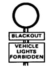
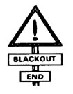
I-41. Place temporary route signs where they will provide warning and reaction time for the drivers. Do not block existing civilian signs. Place warning panels at convenient distances from where a route regulation takes effect. This distance can be shown on the panel (for example, BLACKOUT 500 METERS). In areas where blackout drive is the rule and drivers are using night-vision equipment, employ IR emitters on signs along routes to help guide the units to their destination. Just like any other light source, ensure that the IR emitters cannot be seen from the air.
I-42. Place guide signs at road junctions to prevent confusion. Put signs on both sides of the road if needed. Place confirmation signs (Table I-3) 150 meters beyond the critical road junctions to let drivers know that they are on the correct route.
Table I-3. Signs Identifying Military Routes and Locations
Table I-3. Signs Identifying Military Routes and Locations (Continued)
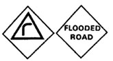

Table I-3. Signs Identifying Military Routes and Locations (Continued)
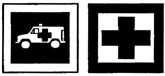
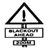
Table I-3. Signs Identifying Military Routes and Locations (Continued)
I-43. Place detour signs next to general traffic signs to identify the detour. Place the detour sign to the side (left or right) of the general sign that corresponds to the new direction to be taken.
I-44. Use signs to mark the entrance to a HQ or an installation along with a halt sign or other regulatory signs. Signs marking turnoffs and roads or tracks should include a directional disk or a directional arrow. Place signs to—
Indicate where vehicles leave a signed route to get to the HQ or the installation.
Mark the road or track leading to the HQ or the installation.
SIGNING FOR KEY POINTS ON ROUTES
I-45. Place countdown signs (Table I-3) at the beginning and end of a route. Clearly mark SPs and RPs with the appropriate countdown signs. Feeder routes to the SP may require signs to help the convoys find it.
I-46. Mark route detours with countdown signs showing the distance to where the detour begins. The signs clearly indicate the route to be detoured.
I-47. Place countdown signs so that they give clear warning of the end of the detour. Mark the end of the detour with a sign reading DETOUR END. Erect a warning sign at the end of the detour to show how to return to the original route.
I-48. Position detour signs ahead of time where terrain will require a defile or the like. Position the signs off the road, facedown on the ground. To implement the detour, erect the signs.
NOTE: The point where a link route meets the circuit is an ideal place for MP control. It is the point where the circuit and the link route begin and end.
I-49. Place signs at junctions of axial and lateral MSRs from all four directions. Place countdown signs 300, 200, and 100 meters before the junction.
I-50. To keep the number of signs to a minimum, battalion-size and smaller groups use a directional sign. The space for the military symbol may contain the UIN or the unit map-marking symbol. Print the UIN or the symbol so that it can be read when the arrow is vertical. This allows the sign to be used as a disk direction.
I-51. Therefore, only one type of sign is needed for all purposes. Put unit signs in place immediately before a unit movement. Remove them as soon as possible after the move.
MAIN SUPPLY ROUTE SIGNS
I-52. MSR signs identify MSRs by number, a pictorial symbol, or a name. Names and pictures—
Prevent confusion with link-route signs marking the routes of units having three-figure identification numbers.
Prevent security compromises by removing the chance use of an identification number already used on a map overlay.
I-53. There are two types of MSRs, axial and lateral, in a theater of operations. On the theater of operation's traffic circulation plan—
Axial MSRs run to and from the forward edge of the battle area (FEBA) and are identified by odd numbers, like 87 or 215. Axial MSRs are shown as solid lines on the traffic circulation plan overlay. Axial routes are represented by a pictorial symbol on the route sign and are marked on the overlay as pictorial; for example, MSR CLUB (PIC). On axial MSRs, up is toward the FEBA. It is shown on overlays and signs as a plain arrow. Down is away from the FEBA. It is shown as an arrow with a bar on the tail end.
Lateral MSRs run parallel to the FEBA and are identified by even numbers, like 86 or 214. Lateral MSRs are shown as broken lines on the traffic circulation plan overlay. A named route sign represents lateral routes. The names are short, three- or four-letter words like fox, ant, or hen. Up and down on lateral MSRs show only general directions of travel. The general direction shown by up or down varies with the theater of operation and with the location of the FEBA. Up is usually to the north or east; down is usually to the south or west. A plain arrow on an overlay or sign indicates up; a barred arrow shows down. To avoid confusion on lateral MSRs, use the letters N, E, S, W, NE, SE, NW, and SW on route signs to show the general direction of movement.
This paragraph implements STANAG 2010. |
I-54. Ensure that all route signs are large enough to be read easily in poor light. Size is not specified, but—
Signs for international use cannot be less than 40 centimeters by 33 centimeters.
Bridge classification signs must conform to STANAG 2010.
LINK ROUTE SIGNS
I-55. There is no set requirements for the design of link route signs (Figure I-10). (Sometimes showing direction with a white arrow on a black background is enough.) A link route connects a unit or an activity to an MSR. A departing convoy follows the link route signs to the MSR. The convoy follows the MSR until guided off the MSR by signs warning of the need to exit and again follow link route signs until arriving at its destination. That part of a traveled route coinciding with an MSR will not have link route signs.
Figure I-10. Link Route Signing
HEADQUARTERS AND INSTALLATION SIGNS
I-56. All signs must be used in HQ and parts of HQ, down to battalion or equivalent level. Examples are—
This paragraph implements STANAG 1059. |
I-57. HQ and installation signs show the military symbol for the HQ or the installation. For HQ at brigade level and above, include the national distinguishing letters given in STANAG 1059. The sizes of the sign and the symbol are not standardized. The symbol and the background must be clearly contrasting colors. The actual colors used are left to the discretion of each nation.
DIRECTIONAL SIGNS
I-58. A directional sign (Table I-3) must be—
A white disk displaying a black directional arrow accompanied by a route identification number or name that can be mounted beneath the disk.
A white disk mounted or superimposed on a black rectangular board with the number or name on the board above the disk.
I-59. Directional disks cannot be less than 30 centimeters in diameter. Drill eight holes in the disks at equal intervals around the circumference so that they can be erected with the arrow pointing in the correct direction.
I-60. Directional signs show directions for axial and lateral routes on hastily prepared routes or very temporary routes like detours. The initial sign shows the use of disk directional signs and orders the drivers to follow the disk direction.
I-61. An MSR may require hundreds of signs. Make the signs in quantity without the black arrow. Stencil or stick the arrows on later. The superimposed signs are easiest to store and use. It is hard to secure the two elements of the circular two-piece signs, and it is hard to position that sign for display.
I-62. Use yellow instead of white for signs used during prolonged snowfall conditions or for signs permanently erected where there can be prolonged snowfalls.
PORTABLE SIGN-MAKING KIT
I-63. The new portable sign-making kit (national stock number [NSN] 9905-01-478-3723) is lightweight and simple to use and contains tools and materials that, when used in conjunction with vehicle BII and locally available materials, produce temporary signs in support of MP operations. Since the kit is not fully self-contained, the user must plan ahead. The new, lighter kit gives MP units the ability to pack according to the METT-TC. Even though a significant difference exists between signs made with the kit and specifications in STANAGs (STANAG route signs generally have a black background with white letters, and the kit's sign background material is white), it does not differ from the kit it replaces. The soft-sided sign kit comes with white plastic bags that can be used to make signs up to 21 inches wide by 23 inches high. Figure I-11, shows a sample sign; and Table I-4, shows a component listing for sign making.
Figure I-11. Sample Sign
|
|
||
|
|
||
|
|
||
Bags, white plastic, trash, 8 gal, roll/box of 20 to 30 (2 each) |
||

|
NEWSLETTER
|
| Join the GlobalSecurity.org mailing list |
|
|
|