Appendix A
Automated Target Data Processing
This appendix explains how AFATDS processes target indicators and suspect targets. The intent of this appendix is to provide targeting and counterfire officers with a detailed understanding of the procedures and functions that AFATDS uses to perform the functions previously performed using manual target cards. It provides the detailed information necessary to effectively use AFATDS to manage the processing of targets and target indicators. This appendix includes AFATDS target generation functions, target indicator processing, suspect target processing, target damage assessment, file maintenance and target purging.
GENERAL
The amount of processing required to develop a target varies extensively. In its simplest form, target data processing is the passing of a target from a known, accurate, and reliable source to the fire control element (FCE) or fire direction center (FDC) for attack within established attack guidance and target selection standards (TSS). In its most complex form, it is the collation of target indicators and suspect targets from diverse sources into a target identification and location accurate enough to justify attack.
In ABCS equipped units, target data is transmitted and processed automatically according to the commander's guidance and TSS stored in the AFATDS computer.
AFATDS uses the Target Generation function to automate the tasks performed by the targeting and target processing elements of the DIVARTY or Field Artillery Brigade TOC. The Target Generation function consists of a series of processes that compare and combine target information to generate targets and update the suspect target list and target indicator file. Target Generation takes suspect targets, Artillery Target Intelligence (ATI) targets, and target indicators (such as shell reports) as inputs, and through several processes eliminates duplication, determines and refines suspect target locations, and generates targets. The Target Generation function can be turned on or off based on the targeting needs in a given tactical situation. The outputs of this function are generated targets and an updated suspect target list and target indicator file. Some key definitions related to Target Generation are:
Target Indicators are directional information that forms a ray (line) from a given point, in a given direction, to a derived maximum distance along which a possible enemy target may be located. Examples of target indicators include shelling, flash, and jam strobe reports. A target indicator will have a target type (e.g. "Artillery, Unknown", "EW Equipment").
Target Data are grid producing information received at AFATDS via a fire request (e.g., a call for fire received from an observer or a fire mission initiated by an AFATDS operator) or intelligence information (e.g., ATI report received from an observer). Target data are also produced by AFATDS. For example, AFATDS uses intersecting target indicator rays to determine a grid location, thereby generating target data.
A target is target data that has passed TSS, and therefore, is worthy of attacking because it meets the commander's criteria for reliability, accuracy, and timeliness. Targets undergo further mission processing to determine if a fire mission will be initiated based on comparisons to additional targeting and attack guidance, the target's relative value to other targets, and if attack systems are capable of engaging the target.
A suspect target is target data that has failed TSS and may not be worthy of attacking because it does not meet the commander's criteria for reliability, accuracy or timeliness. Suspect targets are further refined until they pass TSS and the operator initiates a fire mission on the suspect target, or the suspect target decays (based on target decay guidance) and is deleted from the suspect target list.
TARGET INDICATOR PROCESSING
ROUTING TARGET INDICATORS
If an Operational Facility (OPFAC) does not routinely process shelling reports, a routing function is available to forward shelling reports to a designated OPFAC for processing. For example, a battalion FSE receives a shelling report from one of his observers. The battalion FSO may direct that the report be forwarded to DIVARTY (or the designated counterfire headquarters). The following procedure is used to forward a shell report. Select "Alerts & Messages" -à "Messages" à "Configure Receiving Setup" and highlight the "Target Indicators" message type and input the DIVARTY address (make sure DIVARTY is in your communications configuration). This procedure routes the shelling report to the appropriate processing element.
AFATDS AUTOMATIC PROCESSING OF TARGET INDICATORS
AFATDS always performs certain functions when a target indicator is initially received whether it was received from an observer or created through operator input. When AFATDS receives target indicator data, some of the information required to process the indicator may or may not be present. AFATDS automatically determines missing information based on reporting observers' unit data and default data files. Missing information is determined as follows:
Target Indicator Number - If the received target indicator does not have a target indicator number, one is assigned based on the next available target indicator number from the OPFAC target indicator number block. The target indicator number must always begin with "II". If a target indicator is received with a number that does not begin with "II", the number will automatically be replaced with an "II" number. AFATDS maintains a target indicator numbering block, which the operator cannot edit. This block goes from "II0000 to II9999".
Note: When you enter a target indicator into AFATDS do not enter a target number (AFATDS will automatically number the indicator).
Target Indicator Decay DTG - If Target Indicator Decay DTG for the target indicator is not provided AFATDS computes the DTG by adding target decay guidance for the target type to the DTG of acquisition/report. The DTG of report will default to the current time if not provided.
Target Type - If the received target indicator does not specify a target type, one is assigned based on the following rules:
– If the weapon type is Artillery: Artillery, Unknown.
– If weapon type is Mortar, the target type is based on the reported caliber, otherwise the target type is Mortar, Unknown. If the caliber of the mortar is reported, AFATDS will determine the target type as shown in Table A-1.
Table A-1. Mortar Caliber Target Type Mapping
|
Reported Caliber |
Target Type |
108-150mm |
Mortar, Heavy |
61-107mm |
Mortar, Medium |
< 60mm |
Mortar, Light |
Not given |
Mortar, Unknown |
Sensor Directional Error - If the target indicator does not include the sensor directional error (mils) then it is determined based on the default value for the reporting sensor's unit data or unit type in Table A-2.
– If the weapon type is Rockets or Missiles: Rocket or Missile, Unknown is used.
– If the weapon type is an Electronic Emitter (or any other electronic target), then the target type is Electronic Warfare Equipment.
Table A-2. Sensor Characteristics
Sensor Type |
Laser On |
Target Location |
Directional |
FO |
Yes |
80 |
10 |
FO |
No |
400 |
10 |
FIST |
Yes |
80 |
5 |
FIST |
No |
400 |
5 |
COLT |
Yes |
80 |
5 |
COLT |
No |
400 |
5 |
Observer not FA |
Yes |
80 |
5 |
Observer not FA |
No |
400 |
5 |
Air Observer |
Yes |
270 |
5 |
Air Observer |
No |
400 |
5 |
Naval Observer |
Yes |
80 |
5 |
Naval Observer |
No |
400 |
5 |
Mortar Observer |
Yes |
80 |
5 |
Mortar Observer |
No |
400 |
5 |
ANGLICO |
Yes |
80 |
5 |
ANGLICO |
No |
400 |
5 |
AFAC |
Yes |
270 |
5 |
AFAC |
No |
400 |
5 |
FCT |
Yes |
270 |
5 |
FCT |
No |
400 |
5 |
Radar AN/TPQ-36 |
N/A |
100 or 1.0% of range |
1 |
Radar AN/TPQ-37 |
N/A |
90 or 0.9% of range |
1 |
Radar AN/TPQ-47 |
N/A |
TBD |
TBD |
JSTARS |
N/A |
400 |
1 |
All Others |
Yes |
400 |
5 |
All Others |
No |
400 |
5 |
Sensor Location - If the sensor location at time of report is not provided, then that sensor unit's most current location is used to determine this value. If no location for the reporting unit is available, the target indicator report is discarded.
TARGET SIMILARITY
AFATDS uses target similarity to determine if targets should be combined or if target indicators are close enough to generate target data. Table A-3 lists target categories, types and their similarity to other targets. The matrix number is the individual number for that target type. The similar to matrix numbers are the targets that are considered similar to the target type. The matrix is also used for target duplication checks.
Table A-3. Similar Target Matrix
Matrix |
Target Type |
Similar To Matrix Number |
1 |
ADA, Heavy |
1, 3, 6, 2, 4, 33, 28 |
2 |
ADA, Light |
2, 3, 6, 1, 4, 33, 28 |
3 |
ADA, Medium |
3, 1, 6, 2, 4, 33, 28 |
4 |
ADA, Missile |
4, 6, 1, 3, 2, 33, 34 |
5 |
ADA, Position Area |
5, 42, 1, 2, 3, 4, 6 |
6 |
ADA, Unknown |
6, 3, 1, 2, 4, 33, 28 |
7 |
Ammunition Dump |
7, 83, 84, 85, 86, 87 |
8 |
CP, Battalion |
8, 11, 12, 10, 13, 9 |
9 |
CP, Division |
9, 11, 8, 10, 13, 12 |
10 |
CP, Forward |
10, 8, 12, 11, 9, 13 |
11 |
CP, Regiment |
11, 9, 8, 19, 13, 12 |
12 |
CP, Small |
12, 10, 8, 13, 9 |
13 |
CP, Unknown |
13, 8, 10, 11, 12, 9 |
14 |
Guidance Equipment |
14, 15, 88, 89, 94 |
15 |
Navigational Aids |
15, 14, 88, 89, 94 |
16 |
Bridge, Floating Pontoon Footbridge |
16, 17, 18, 45, 61, 60, 62, 63 |
17 |
Bridge, Floating Pontoon Vehicle |
17, 16, 18, 45, 61, 60, 62, 63 |
18 |
Bridge, Footbridge, Raft |
18, 16, 17, 45, 61, 60, 62, 63 |
19 |
Building, Concrete |
19, 20, 21, 22, 23, 24 |
20 |
Building, Unknown |
20, 19, 21, 22, 23, 24 |
21 |
Building, Masonry |
21, 19, 20, 22, 23, 24 |
22 |
Building, Special Purpose |
22, 19, 20, 21, 23, 24 |
23 |
Building, Metal |
23, 19, 20, 21, 22, 24 |
24 |
Building, Wood |
24, 19, 20, 21, 22, 23 |
25 |
Bunker |
25, 26 |
26 |
Pillbox |
26, 25 |
27 |
Artillery, Heavy Self-Propelled |
27, 29, 28, 31, 30 |
28 |
Artillery, Light Self-Propelled |
28, 29, 30, 31, 27, 38, 35 |
29 |
Artillery, Medium Self-Propelled |
29, 27, 28, 31, 30 |
30 |
Artillery, Towed |
30, 31, 28, 29, 27, 38, 35 |
31 |
Artillery, Unknown |
31, 29, 30, 28,27 |
32 |
Missile, Heavy |
32, 34, 33, 4 |
33 |
Missile, Light |
33, 34, 40, 41, 32, 43, 4 |
34 |
Missile, Medium |
34, 32, 33, 4 |
35 |
Mortar, Heavy |
35, 37, 38, 39, 36, 28, 30 |
36 |
Mortar, Light |
36, 37, 39, 35, 38, 28, 30 |
37 |
Mortar, Medium |
37, 36, 35, 39, 38, 28, 30 |
38 |
Mortar, Very Heavy |
38, 35, 37, 39, 36, 28, 30 |
39 |
Mortar, Unknown |
39, 35, 37, 38, 36, 28, 30 |
40 |
Rocket-Missile, Anti-Personnel |
40, 41, 33, 64, 43 |
41 |
Rocket-Missile, Anti-Tank |
41, 40, 64, 33, 43 |
42 |
Rocket-Missile, Position Area |
42, 5, 40, 41 |
43 |
Rocket-Missile, Unknown |
43, 40, 41, 43 |
44 |
Boat |
44, 48, 47, 46, 52 |
45 |
Ferry Bridge |
45, 16, 17, 18, 63 |
46 |
Helicopter, Attack |
46, 47, 48, 52, 44 |
47 |
Helicopter, Cargo |
47, 46, 48, 52, 44 |
48 |
Helicopter, Observation |
48, 46, 47, 52, 44 |
49 |
Vehicle, Heavy Wheel |
49, 50, 51, 95 |
50 |
Vehicle, Light Wheel |
50, 49, 51, 95 |
51 |
Vehicle, Utility |
51, 49, 50, 95 |
52 |
Aircraft |
52, 46, 47, 48, 44 |
53 |
Defile |
53, 59, 54, 57, 58, 55, 56 |
54 |
Hill |
54, 59, 53, 57, 58, 55, 56 |
55 |
Landing Strip |
55, 58, 56, 57, 59, 53, 54 |
56 |
Railroad Segment |
56, 58, 55, 57, 59, 53, 54 |
57 |
Road Junction |
57, 55, 56, 58, 59, 53, 54 |
58 |
Road Segment |
58, 55, 56, 57, 59, 53, 54 |
59 |
Terrain Feature |
59, 53, 54, 55, 56, 57, 58 |
60 |
Bridge, Vehicle, Concrete |
60, 62, 61, 17, 16, 18, 63 |
61 |
Bridge, Vehicle, Wood |
61, 18, 60, 62, 17, 16, 63 |
62 |
Bridge, Vehicle, Steel |
62, 60, 61, 17, 16, 18, 63 |
63 |
Bridge Site |
63, 16, 17, 18, 45, 60, 61 |
64 |
Anti-Tank Gun |
64, 77, 41, 40 |
65 |
Armored Personnel Carrier |
65, 66, 79, 80, 78 |
66 |
Armored Vehicle |
66, 65, 79, 80, 78 |
67 |
Assembly Area, Mechanized Troops |
67, 70, 69, 71, 68 |
68 |
Assembly Area, Troops |
68, 70, 67, 69, 71 |
69 |
Assembly Area, Troops and Armor |
69, 67, 70, 68, 71 |
70 |
Assembly Area, Troops and Vehicles |
70, 67, 69, 68, 71 |
71 |
Assembly Area, Unknown |
71, 68, 70, 67, 69 |
72 |
Infantry |
72, 76, 81, 75, 74, 82, 73 |
73 |
Machine Gun, Heavy |
73, 82, 74, 72, 76, 81 |
74 |
Machine Gun, Light |
74, 82, 73, 72, 76, 81 |
75 |
Observation Post |
75, 12, 76, 72, 81 |
76 |
Patrol |
76, 72, 81, 75, 74, 82, 73 |
77 |
Recoilless Rifle |
77, 64, 40, 41 |
78 |
Tank, Heavy |
78, 80, 79, 66, 65 |
79 |
Tank, Light |
79, 80, 78, 66, 65 |
80 |
Tank, Medium |
80, 78, 79, 66, 65 |
81 |
Work Party |
81, 76, 72, 75, 74, 82, 73 |
82 |
Weapon, Crew Served |
82, 73, 74, 72, 76, 81 |
83 |
Class I Supply Dump |
83, 84, 7, 86, 87, 85 |
84 |
Class II Supply Dump |
84, 83, 7, 86, 87, 85 |
85 |
Supply Dump, Unknown |
85, 83, 84, 7, 86, 87 |
86 |
Chemical Products Complex |
86, 87, 83, 84, 7, 85 |
87 |
Petroleum Products Complex |
87, 86, 83, 84, 7, 85 |
89 |
Electronic Warfare Equipment |
89, 88, 94, 14, 15, 93, 91, 92, 90 |
90 |
Counter-Battery Radar |
90, 91, 92, 93, 94, 89, 88 |
91 |
Counter-Mortar Radar |
91, 90, 92, 93, 94, 89, 88 |
92 |
Direction Finding Radar |
92, 91, 90, 93, 94, 89, 88 |
93 |
Ground Surveillance Radar |
93, 92, 91, 90, 94, 89, 88 |
94 |
Search Light |
94, 88, 89, 14, 15, 93, 92, 91, 90 |
95 |
Reconnaissance Vehicle |
95, 49, 50, 51 |
DIRECTION AND DISTANCE
The direction and distance of the target indicator ray is determined by:
Direction of ray originates from the sensor/shell impact location.
Length of ray is based on the following:
– Use length provided, if given.
– If a flash to bang is provided, use Distance = 350 X Time (sec). The result is the length of ray in meters.
– If length or flash to bang time is not provided, the ray length is based on the target type as shown in Table A-4:
Table A-4. Default Target Indicator Length
Target Type |
Ray Length (meters) |
Mortar, Very Heavy |
9700 |
Mortar, Heavy |
7200 |
Mortar, Medium |
7200 |
Mortar, Light |
4200 |
Mortar, Unknown |
7200 |
Artillery, Heavy, SP |
37,500 |
Artillery, Medium, SP |
24,700 |
Artillery, Light, SP |
15,300 |
Artillery, Towed |
24,700 |
Artillery, Unknown |
24,700 |
Rocket/Missile, Anti-Personnel |
30,000 |
Rocket/Missile, Anti-Tank |
30,000 |
Rocket/Missile, Position Area |
30,000 |
Rocket/Missile, Unknown |
30,000 |
Missile, Heavy |
300,000 |
Missile, Medium |
100,000 |
Missile, Light |
100,000 |
Electronic Warfare Equipment |
30,000 |
DISPLAY
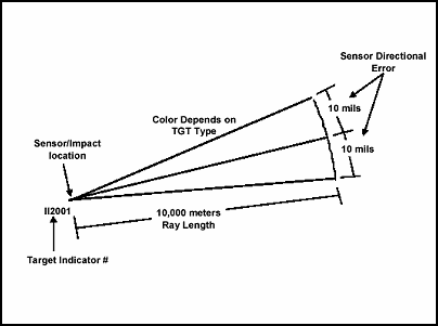
Target indicators are displayed as "fans" based on the sensor directional error. Figure A-1 shows a target indicator with a 10,000 meter length and a sensor directional error of 10 mils.
Figure A-1. Target Indicator Display
Each target indicator ray has an assigned color based on target type. The colors of target indicator rays are shown in Table A-5.
Table A-5. Default Target Indicator Color
Target Type |
Ray Color |
Mortar, Very Heavy |
Yellow |
Mortar, Heavy |
Yellow |
Mortar, Medium |
Yellow |
Mortar, Light |
Yellow |
Mortar, Unknown |
Yellow |
Artillery, Heavy, SP |
Red |
Artillery, Medium, SP |
Green |
Artillery, Light, SP |
Blue |
Artillery, Towed |
Green |
Artillery, Unknown |
Black |
Rocket/Missile, Anti-Personnel |
Orange |
Rocket/Missile, Anti-Tank |
Orange |
Rocket/Missile, Position area |
Orange |
Rocket/Missile, Unknown |
Orange |
Missile, Heavy |
Orange |
Missile, Medium |
Orange |
Missile, Light |
Orange |
Electronic Warfare Equipment |
Black |
TARGET INDICATOR FUNCTION
Based on the tactical situation, the AFATDS operator may or may not want the system to run the Target Indicator function. AFATDS allows the operator to turn target indicator processing on or off. When the target indicator processing is "off", AFATDS adds the target indicator to the target indicator list with no additional processing or comparisons. When Target Indicator Processing is "on", AFATDS performs the following checks (in order):
Compares the target indicator against the current (but non-active) target files (i.e. targets on the "On-call", "Suspect", "Planned" and "Inactive" target lists). If the indicator ray covers a similar target, the OPFAC with target indicator processing duty is notified of the "Target Indicator Match" via an alert and reviews information on the target indicator and all matched targets. The operator may take various actions from this alert:
– Selectively initiate fire mission(s) against the target(s) indicated as a match. This will open the initiate fire mission screen already filled out for the selected target.
– Add selected matched target(s) to an existing fire plan. This will place the targets on the selected fire plan.
– Display the target indicator fan-target comparison. This graphically displays the indicator fan and the associated matched target(s) on the map.
– Selectively update matched target(s) with a new "last updated" value based on the target indicator DTG of acquisition/report.
– Delete the target indicator. This will discard the received target indicator data and will not add it to the target indicator list.
– Continue Processing the Target Indicator. This will add the target indicator to the target indicator list for possible combination with existing target indicators.
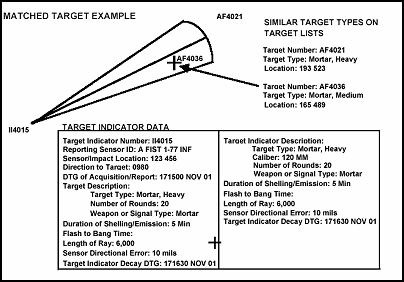
Compare the target indicator with other target indicators already on file. If the target indicator did not match a target or the operator selected "Process TI" from the target match window, AFATDS will add the new target indicator to the target indicator list and determine if it can be combined with existing target indicators. See Figure A-2 for an example of target comparison The following rules are used in this comparison:
– The new target indicator is compared against existing target indicators in the target indicator file that have a similar target type. Only target indicators that have not passed their decay DTG are considered.
– When target indicator rays of three or more of the compared target indicators intersect to form a point or common area, and all points are located within 400 meters, AFATDS automatically combines the rays and generates a new target number and passes the target to the TSS check for further processing. Combined TIs are deleted from the TI list.
– If no match is found, the new target indicator is added to the target indicator file. The operator can purge the target indicator list of target indicators when their "decay time" DTG is passed. To do this simply select "automatically purge" option on the target indicator list window.
Figure A-2. Target Indicators-Target Comparison
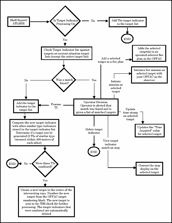
Figure A-3 provides a summary of the possible results of target indicator processing.
Figure A-3. Target Indicator Processing
SUSPECT TARGET PROCESSING
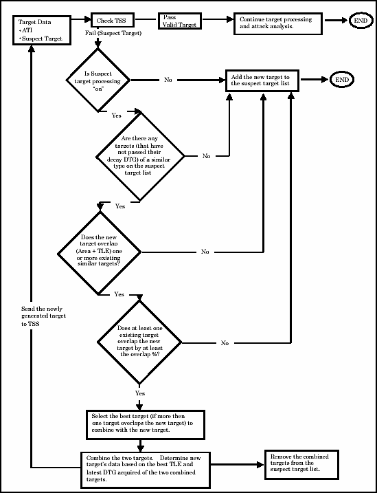
Suspect targets represent target information that has not passed TSS. This section discusses how AFATDS processes suspect targets after TSS failure. The operator may turn Suspect Target Processing "on" or "off". When it is turned off, all suspect targets are simply added to the suspect target list with no further processing. When it is turned on, AFATDS evaluates each suspect target against other suspect targets to combine the new suspect target with an existing suspect target and generate a target with a better TLE and/or more current DTG. AFATDS applies the following considerations when identifying suspect targets for combination and applying the associated target data for the "new" (combined) target:
Decay Time. Only suspect targets that have not passed their decay DTG are considered for combination.
Target Type. Only targets with a similar type will be considered for combination. For example, an "Artillery, Unknown" target would not be combined with a "Building, Metal" target.
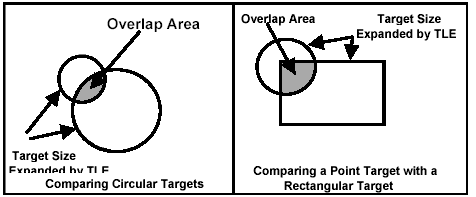
Target Size. The target size and TLE, for the new or extracted suspect targets is used to determine overlap. If an overlap exists between the new target and a single existing target and the overlap area meets or exceeds the operator established percentage of overlap required, then the two targets match. Basically, the overlap percentage tells AFATDS how close two targets must be (considering the area and TLE of each target) in order to combine them. Figure A-4 shows some examples of this comparison.
Figure A-4 Suspect Target Overlap
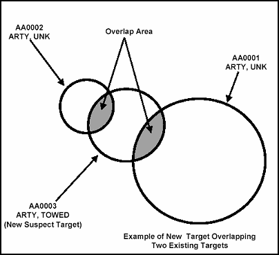
If multiple overlaps exists between the new suspect target and two or more existing suspect targets and each overlap area meets or exceeds the operator established percentage of overlap required, then the following rules apply:
The suspect target with the greater degree of similarity to the new suspect target is combined with the new suspect target.
If the degree of similarity is the same, the suspect target with the greater degree of overlap with the new suspect target is combined with the new suspect target. Figure A-5 illustrates multiple target overlap.
Figure A-5. Multiple Target Overlap
When two targets are combined, the new target is sent to TSS for further processing. Both of the "parent" targets (the two that were combined) are removed from the suspect target list.
The operator may specify the "Overlap %" to be used by AFATDS when considering targets for combination. A larger percentage (like 75%) will result in fewer, but more accurate, combinations than a smaller percentage (like 25%). As with the target indicator list, the operator may decide to have the suspect target list purged of targets when their "decay time" DTG is passed. To do this simply select "automatically purge" option on the suspect target list window. Finally, the operator may see the targets on the suspect target list that were generated by AFATDS (these will be the targets that have a "yes" in the "Combined?" column of the list). There is an option to "uncombine" a combined target if desired.
CONSIDERATIONS FOR RECEIVING ATI MESSAGES FROM PACKAGE 10 IFSAS.
An ATI;CDR message received from IFSAS could be treated as a fire request, intelligence data, mission fired report (MFR), On-Call Target, or Planned Target depending upon the information contained in the message. Table A-6 summarizes the various dispositions possible for an ATI message received by AFATDS.
Table A-6. ATI Results When Received From IFSAS
Fire Request Indicator |
Mission Fired Indicator |
Record Target Indicator |
Confirm Target Location |
Delete Target |
Update Target |
Disposition |
Yes |
N/A |
N/A |
N/A |
N/A |
N/A |
Fire Request |
No |
Yes |
N/A |
N/A |
N/A |
N/A |
MFR |
No |
No |
Yes |
N/A |
N/A |
N/A |
Record As Target (On Call List) |
No |
No |
No |
Yes |
N/A |
N/A |
Planned Target List |
No |
No |
No |
No |
N/A |
N/A |
Suspect Target |
No |
N/A |
N/A |
N/A |
Yes |
N/A |
Planned Target List (Update) |
No |
N/A |
N/A |
N/A |
N/A |
Yes |
Planned Target List (Update) |
CONSIDERATIONS FOR RECEIVING ATI MESSAGES FROM PACKAGE 11 IFSAS.
An ATI message received from a Package 11 device could be treated as a fire request, intelligence data, MFR, On-Call Target, or Planned Target depending upon the information contained in the message. Table A-7 summarizes the various dispositions possible for an ATI received by AFATDS.
Table A-7. Suspect Target Processing
Mission Fired Indicator Set? |
Target Number Provided and Message Action is "Change " or "Delete" |
Message Designator is "Shell Report" |
Message Action is not Specified and Target Data (Number, Type, and Location is Provided) |
Message is ATI "Coordinate " or "ATI Azimuth" and Message Action is "Add" |
Disposition |
Yes |
N/A |
N/A |
N/A |
N/A |
MFR |
No |
Yes |
N/A |
N/A |
N/A |
Planned Target List (Update) |
No |
No |
Yes |
N/A |
N/A |
Target Indicator |
No |
No |
No |
Yes |
N/A |
Target Info Query Request |
No |
No |
No |
No |
Yes |
ATI Sent To TSS |
If the message does not fit into the rules contained in Table A-7, it will be displayed upon receipt to the AFATDS operator. A summary of the possible results of suspect target processing is provided in Figure A-6.
Figure A-6. Suspect Target Processing
TARGET DAMAGE ASSESSMENT
Target Damage Assessment (TDA) is a function of AFATDS that allows target disposition to be entered by the observer on the MFR after attack of a target. TDA can be flagged in the commanders guidance of AFATDS, causing targets to remain active until disposition is received from the observer for the particular target. TDA in AFATDS guidance is target type specific. Therefore, it is not very useful in the determination of TDA on a particular target generated from the suspect target processing function. Flagging an individual target type in the target management matrix (TMM) will cause that target type to remain active until the reporting sensor sends a MFR for that target that contains target damage. This requires eyes on target. A target generated by the suspect target or target indicator processing function will have the processing AFATDS station as the observer. This station very seldom has eyes on target.
FILE MAINTENANCE AND TARGET PURGING
File maintenance for suspect target and target indicator processing consists of purging targets that are no longer valid. This can be done manually or automatically. Manually deleting targets from the suspect target or target indicator list involves selecting the target list requiring maintenance and reviewing individual targets, and validating or deleting individual targets from the target list. The most effective method of performing file maintenance is to set target purging to automatic. This automatically purges targets based on the target decay time established in the TSS. This is accomplished by selecting "Automatic Purge" on the suspect target or target indicator list.
|
NEWSLETTER
|
| Join the GlobalSecurity.org mailing list |
|
|
|


