Chapter 2
LAN Installation
Linking BFACSs in a local geographical area creates a LAN. The LAN provides the path for data to travel gathering and sharing information. This chapter discusses the components used in installing a LAN, the different network configurations, and the router- and switched-based architectures.
LAN CONFIGURATION
2-1. The LAN configuration and protocols used depend on the mission of the unit and the commanders' intent. For a LAN to function effectively, it must be well planned. The hardware, software, and peripherals used must interoperate with one another. Certain hardware and software requirements must be met and installed
BFACSs
2-2. Computers are electronic devices operating under the instructions stored in the memory unit. Computers can accept and process data (input), produce results (output) from the processing, and store the data for future use. Computers can also communicate by sending and receiving data to other computers connected to a LAN.
2-3. The ABCS computers are the C2 systems that are software unique for each BFA. They provide maneuver, FS, AD, intelligence and EP, and CSS information. These systems can provide e-mail, facsimile, electronic data exchange, global positioning systems, and Internet and video teleconferencing. The configuration of these systems depends on the unit's mission.
NETWORK INTERFACE CARD (NIC)
2-4. A NIC is a circuit card that fits in an expansion slot of a computer or other device. Most NICs require a cable connection and have connectors on the card for different types of cables. A NIC has circuits that coordinate transmitting and receiving data and check errors of transmitted data.
2-5. NICs are built into hardware-like routers and switches and require no hardware configuration. For laptop computers, the NIC is the personal computer (PC) card and requires little or no configuration. The configuration process for many NICs will differ based on whether the NIC is installed in a server or a workstation. Different drivers are required for different operating systems. Figure 2-1 shows an example of a NIC connected by a T-connector with a coaxial cable or RJ-45 cable.

Figure 2-1. Example of a NIC
2-6. The NIC-
- Provides power to the transceiver.
- Buffers and decodes the received frames.
- Builds frames to be sent out on the network.
- Interfaces with PCs and the PC's central processing unit.
- Performs parallel to serial conversion.
- Provides a workstation with a unique address.
- Computes back off time when a collision is detected by the transceiver.
TRANSMISSION MEDIA
2-7. The TOC LAN can use coaxial cable, twisted-pair cable, fiber-optic (FO) cable, wire, radio frequency, infrared, or laser beam (wireless). The signals travel over these media from one device to another device.
COAXIAL CABLE
2-8. Coaxial cable is a high-quality, heavily insulated communications line. It consists of a nonconducting insulator surrounded by a woven metal outer conductor and a plastic outer coating. It is not susceptible to electrical interference and transmits data faster over longer distances.
10Base2 Thinnet
2-9. The 10Base2 Thinnet is an RG-58 coaxial cable that is about 0.25 inches in diameter. The connectors are twist-on Bayonet Neill Concelman (BNC) with crimped connection to the wire. BNC always refers to 10Base2 connectors. The cable is limited to 185 meters in length. No more than 30 stations can be attached, and they must be separated by 0.5 meters. Multiple segments can be connected into a larger LAN with repeaters. The 10Base2 Thinnet coaxial cable uses T-connectors to connect a NIC to the medium. It must have a 50-ohm terminator at each segment end. Figure 2-2 shows an example of a basic 10Base2 LAN. Figure 2-3 shows an example of T-connectors to a NIC.
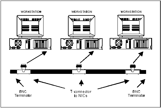
Figure 2-2. Example of a Basic 10Base2 LAN
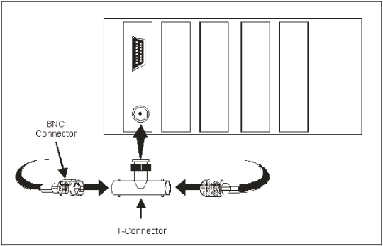
Figure 2-3. Example of T-connectors to a NIC
10Base5 Thicknet
2-10 The 10Base5-Thicknet coaxial cable is about 0.5 inches in diameter and limited to 100 connections per 500-meter length line segments. A repeater or bridge connects multiple segments. Thicknet coaxial cable has transceivers that attach to the medium. The attachment unit interface (AUI) cable attaches the media access unit (MAU) on the RG-8 cable to either a NIC or a multiport repeater. Workstations and servers are connected exactly the same way either directly or through a repeater. However, the server attaches directly to the transceiver. Figure 2-4 shows an example of the basic connections for a 10Base5 bus LAN. DIX connectors refer to the three companies (Digital, Intel, and Xerox) that developed Ethernet. These connectors have 15-pin male and female connectors. Figure 2-5 shows an example of the male and female DIX connectors.
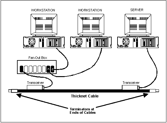
Figure 2-4. Example of Basic Connections for a 10Base5 Bus LAN
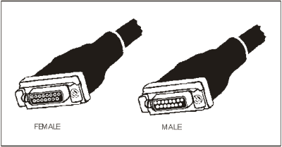
Figure 2-5. Example of the Male and Female DIX Connectors
TWISTED-PAIR CABLE
2-11. Twisted-pair cable consists of plastic coated copper wires that are twisted together. A thin layer of colored plastic insulates and identifies each wire. The wires are twisted to reduce electrical interference. Shielded-twisted pair (STP) cable has a foil wrapper around each wire that further reduces electrical interference. UTP cable does not have the foil wrapper. Twisted-pair cable is an inexpensive transmission medium that can be installed easily.
100BaseTX
2-12. A specification of fast Ethernet is copper cables with one device per maximum segment length of 100 meters. Segments connected to 10BaseT hubs or 10/100Base switches normally use 4-pair, American wire gage (AWG) 22, 24, or 26 unshielded-twisted pair (UTP) cables. The connectors are RJ-45 connectors (8-wire telephone type connectors, category 5 UTP can be substituted for best results). Maximum distance is 205 meters unless additional switches or extension devices are used.
10BaseT
2-13. The 10BaseT is a UTP cable used to connect workstations to 10BaseT hubs and hubs-to-hubs. It is faster and has less chance of failure due to cabling, since it uses fewer parts than BNC. Each hub shares bandwidth and takes a portion of the total bandwidth (10 megabits (mbps)). The 10BaseT's maximum segment length is 100 meters with one device per segment. Segments connect devices to 10BaseT hubs and each cable is a 4-pair, AWG 22, 24, or 26 UTP. The connectors are RJ-45 connectors (8-wire telephone type connectors). Figure 2-6 shows an example of a 10BaseT LAN.
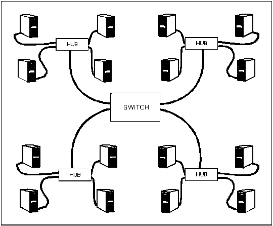
Figure 2-6. Example of a 10BaseT LAN
FO CABLE
2-14. FO cable uses smooth, hair-thin strands of glass or plastic to transmit data as pulses of light. The major advantages of FO cables over wire cables include substantial weight and size savings and reduced electrical and magnetic interference. FO cable has a higher carrying capacity carrying several hundred thousand voice communications simultaneously. FO cable is better than twisted pair or coaxial; however, it can be difficult to install and repair.
10BaseFL
2-15. The 10BaseFL can connect up to 2 kilometers (1.2 miles). The cable is either 50, 62.5, or 100-micron, duplex, multimode FO cable. Devices with AUI (DIX) connectors require an FO transceiver. The speed of the 10BaseFL is 10 mbps. Figure 2-7 gives an example of a 10BaseFL fiber link between sites.
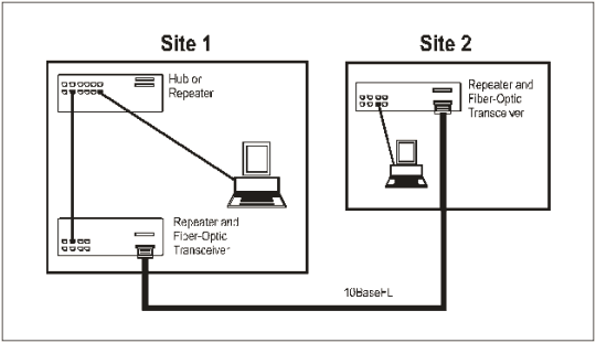
Figure 2-7. Example of a 10BaseFL Fiber Link Between Sites
100BaseFX
2-16. The 100BaseFX is a physical layer standard using FO cables running at 100 mbps. They connect multiple Ethernet LANs, act as a high-speed bridge, and are most often set up in a star configuration. This configuration will access servers attached to one or more 100 mbps ports. The LANs are attached on 10 mbps ports for extremely fast transfer of packets from one LAN to another LAN or device through the switch. Figure 2-8 shows an example of a 100BaseFX LAN.
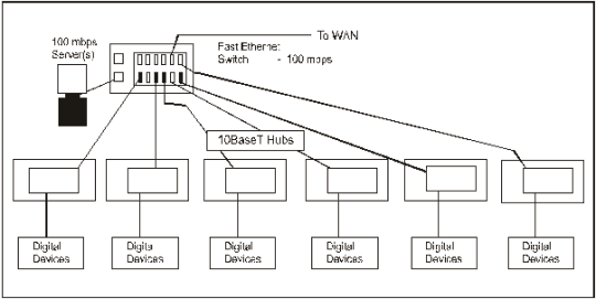
Figure 2-8. Example of a 100BaseFX LAN
WIRELESS
2-17. Wireless transmission technology uses infrared or laser beams to transmit data between computers without connecting them with a cable.
COMMUNICATION PROTOCOLS
2-18. A protocol is a set of rules and procedures for exchanging information between computers. Protocols define how the communications link is established, how information is transmitted, and how errors are detected and corrected. The two most used protocols are Ethernet and token ring.
ETHERNET
2-19. Ethernet is the most widely used network protocol for LAN networks. Ethernet is based on a bus topology but can be wired in a star pattern by using a wiring hub. Most networks transmit data at 10 mbps. A higher speed version of Ethernet is the Fast Ethernet, and it can transmit data at 100 mbps.
2-20. A packet of data can be sent in both directions along the bus whenever a node is ready to transmit. The packet, which contains the destination address and sending address, travels along the network until it arrives at the designated receiving device. When a collision occurs, the network adapter cards send out a jam signal. This signal lets the conflicting nodes know that there is a collision. Each adapter stops transmitting and a unique back off period calculates when to retransmit the data. This ensures that the collision does not occur again when the nodes try to resend the data.
2-21. When a network uses carrier sense multiple access/collision detect (CSMA/CD), all computers are equal when it comes to accessing the media. Every computer on the network receives every frame that is transmitted, unless switches are used.
CONNECTIVITY DEVICES
2-22. Tactical LANs are interconnected using routers, switches, bridges, repeaters, and hubs.
ROUTERS
2-23. Routers allow addressees to change as needed for jump and/or split TOC operations. Routers are used when several networks are connected together. A router is an intelligent network-connecting device that sends (routes) communications traffic directly to the appropriate network. In the event of a network failure, routers are smart enough to determine alternate routes.
SWITCHES
2-24. A switch connects LAN segments and a high-speed port. A LAN switch has a dedicated bandwidth per port. When a LAN switch is powered up and the devices that are connected to it request services from other devices, the switch builds a table that associates addresses of each local device with the port number through which that device is reachable.
BRIDGES
2-25. A bridge connects two or more LANs that use identical LAN media access control (MAC) layer protocols. A bridge forwards frames between LAN segments using information it finds in the open systems interconnect reference model (OSI RM) Layer 2 of a packet. It looks at the destination address and compares the address to its address tables. If it finds the address associated with a port, it sends the packet out on that port. If it does not find an address, it sends the packet out on all ports.
2-26. Multibridges usually communicate with each other using the IEEE 802.1d spanning tree algorithm protocol or other protocol. Pure transparent and source routing bridging are most effective when there are fewer links in the network. Larger networks usually use routers where links are numerous. Transparent bridges send frames or packets out a port; they do not route them to another device.
REPEATERS
2-27. Repeaters provide the cheapest and least intelligent connections between segments of a LAN or between closely located LANs. Repeaters simply take the input (signals) and regenerate the signals on all other ports on the repeater at its original voltage.
2-28. Multiport repeaters primarily connect several 10Base2 segments of an Ethernet/802.3 LAN. This repeater has one AUI port and six 10Base2 ports. Repeater (half) sets generally connect segments of a LAN located more than 100 meters apart. FO is the generally accepted media between repeater sets. For less than 100 meters, AUI cable can connect 10Base5 segments.
NOTE: Repeaters do not control or reduce traffic between LAN segments or between LANs. Attempting to run too many segments can result in too long a distance and increased collisions due to that distance. IEEE standards say that a frame cannot pass through more than four repeaters between a sending and a receiving station.
HUBS
2-29. Wiring hubs allow devices such as computers, printers, and storage devices to connect to the server. The hub acts as the central connecting point for cables that run to the server and each of the devices on a network. A stackable hub can connect with another hub to increase the number of devices attached to the server.
NETWORK CONFIGURATIONS
2-30. Topology is the way equipment is configured in a LAN. The logical connection of the devices in the network determines the typology and the path the data follows as it is routed from one device to another. The actual physical connections may form a different shape than the one formed by the devices in the network. The more common topologies are bus, star, and ring. Combinations of these topologies also are used.
BUS NETWORK
2-31. In a bus network, all the devices or nodes are connected to and share a single path. Bus networks allow data to be transmitted in both directions. Each time data is sent out a destination address is included with the transmission so the data is routed to the appropriate receiving station. A bus network can be wired with a wiring hub at the center so it looks like a star network. An advantage of the bus network is that devices can be attached or detached from the network at any point without disturbing the rest of the network. Also if one computer in the network fails, this does not effect the rest of the network. Figure 2-9 shows an example of a bus network.
STAR NETWORK
2-32. In a star network, a central computer with one or more terminals or smaller computers are connected forming a star. A star network consists of only point-to-point lines between the central computer and the other computers on the network. The disadvantage of a star network is that the network relies on the central computer's hardware and software. If any of these elements fail, the entire network is disabled. In a star network, back-up computer systems are kept available in case of system failure. Figure 2-10 shows an example of a star network.
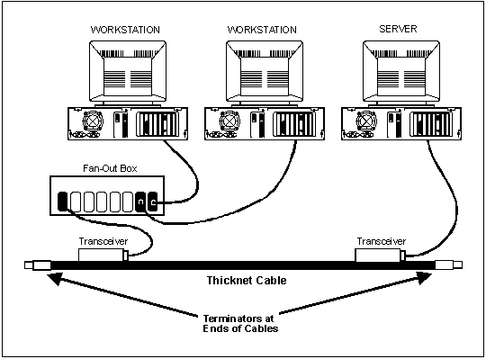
Figure 2-9. Example of a Bus Network

Figure 2-10. Example of a Star Network
Ring Network
2-33. In a ring network, all devices on the network are connected in a continuous loop or ring. A ring network does not use a centralized host computer. In the ring network, computers connect and communicate in a circular pattern. Data travels around in one direction only and passes through each computer. Ring networks sometimes connect large computers in the same area that share data frequently. One disadvantage of a ring network is that if one computer fails, the entire network fails because the data cannot be transmitted past the failed computer. Figure 2-11 shows an example of a ring network.

Figure 2-11. Example of a Ring Network
TOKEN RING
2-34. In a token-ring network, computers are configured in a ring and a message called a token is passed from computer to computer The token is used to avoid conflicts in transmission. A computer can only transmit messages while it holds the token. The computer keeps the token while transmitting a message and then passes it on to the next computer. While the computer is transmitting a message, other stations must wait.
2-35. The receiving computer copies the data and it continues around the ring until it gets to the computer that transmitted the original message. That computer then purges the busy token and inserts a new free token and the process starts over with a new computer transmitting a message.
2-36. Token-ring networks run over twisted-pair cabling with a length limited to 150 feet between the MAU and the computer. This cable can be either STP or UTP. UTP is cheaper but tends to have interference problems. STP is the more stable.
ROUTER-BASED ARCHITECTURE
2-37. The TOC LAN consists of several separate LANs interconnected by routers. The TOC LAN interconnects the various TOC shelters. The intervehicle LAN is external and uses a router AUI 1 LAN port. The intravehicle LAN is internal and uses a router AUI 0 LAN port. The intervehicle LAN interconnects the BFA workstations within a shelter. Thus, the host can keep their IP address wherever their vehicle attaches to the network. The host tables can stay the same while the routing protocols quickly announce the new route. The fire support element shelter has an additional LAN that extends the AFATDS workstation into the TOC Standard Integrated Command Post Systems (SICPSs). So, within a multiple shelter TOC, there could be multiple intervehicle LANs. Figure 2-12 shows an example of tactical LAN connectivity.
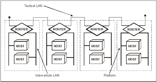
Figure 2-12. Example of Tactical LAN Connectivity
2-38. The LAN is configured as a single continuous bus and is terminated at each end with a 50-ohm terminator. To minimize coaxial stub lengths, T-connectors connect directly to the equipment. The IEEE 802.3 Type 10Base2 LAN is limited to 185 meters (about 600 feet) and 30 MAUs. Each shelter has about 50 feet of internal cabling. Four interconnected SICPSs will give an internal total cable length of about 200 feet.
2-39. The LAN must have a single-point ground for the coaxial cable segment, even if the segment consists of cable sections from multiple SICPSs. Standing operating procedures (SOPs) must be established for grounding TOC LANs. This helps the user understand who is responsible for grounding the LAN and in which vehicle.
2-40. For a single SICPS LAN with no coaxial connections to other SICPSs, the terminator plugs connect to the LAN connectors at the single entry panel (SEP) and the tent interface panel (TIP). A multiple SICPS LAN requires a terminator at the SEP of the first SICPS and another terminator at the TIP of the last SICPS on the Thinlan bus.
2-41.The FO LAN connects to the TOC LAN when the 185-meter maximum cable run is exceeded. All equipment connected to the FO LAN must be IEEE 802.3. The FO cable is not subject to the electrical constraints limiting the coaxial LAN. These electrical constraints include lightning, electromagnetic interference (EMI), grounding, and shock hazards.
2-42. The battalion/brigade support area (BSA) and the battalion TOC intervehicle LANs connect in daisy chain configuration. They connect to the TOC LAN at the vehicle's TIP of the first vehicle and to LAN B on the SEP of the second vehicle. This method continues until the last vehicle is connected. The BSA and the battalion TOC intervehicle LANs terminate at LAN B on the SEP of the first vehicle and LAN B on the TIP of the last vehicle. The vehicle of the deputy G6 and/or the S6 connects onto the TOC LAN. Figure 2-13 shows an example of a router-based architecture.
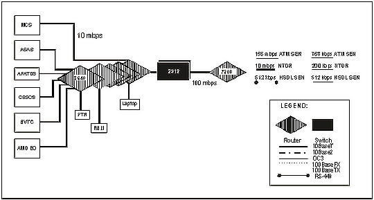
Figure 2-13. Example of a Router-Based Architecture
2-43. The division and the brigade TOC intervehicle LANs connect in a star configuration with a central Ethernet switch hub. Separate intervehicle TOC LAN segments connect to the LAN hub. Each intervehicle LAN segment directly connects to the vehicle TIP LAN B connector without a tee and at the Ethernet switch using a coaxial tee and terminator. LAN A and B ports terminate on the vehicle's SEP. The intravehicle LAN's TIP LAN A port extends the LAN's access to workstations in the TOC's tent complexes. When intravehicle LANs extend from a vehicle to a TOC tent complex, the TIP LAN A terminator is removed and is replaced with a LAN segment (a coaxial T-connector and terminator). Extended intravehicle LANs terminate at the workstation.
2-44. Division and brigade jump and/or split TOC operations use the battalion TOC LAN daisy chain configuration until the TOC hub arrives. AFATDS intervehicle LANs will use additional LAN C ports and the daisy chain configuration.
SWITCHED-BASED ARCHITECTURE
2-45. A switched LAN consists of several Ethernet switches that extend to a central switch and a central router. Some TOCs may have multiple central switches and central routers. The central switch provides the interface from the cell switches to the central router. At the designated vehicle, the central router provides communications between cells and connectivity to the wide area network (WAN). The C LAN exists for the AFATDS intervehicle LANs. The switches in these TOCs automatically identify who is connected to its ports by the MAC address. Thus, the switch can broadcast traffic immediately to a port using the store and forward procedure. The procedure increases the performance of the LAN since there is no collision factor. The central router will have the open shortest-path first and the border gateway protocol to allow for inter- and intra-administrative borders. Figure 2-14 shows an example of a switched-based architecture.
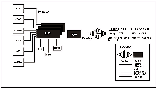
Figure 2-14. Example of a Switched-Based Architecture
2-46. The intervehicle LANs connect in a star configuration to a central Ethernet switch. The FO cable has one pair per connection: one transmit and one receive. When connecting the fiber, the ends must be swapped so one end transmits and one end receives. The IEEE 802.3 Type 10BaseT and 100BaseTX LAN distance limitation is 100 meters (about 328 feet). The 100BaseFX distance limitation is 412 meters (about 1351 feet). The optical carrier (level 3) OC3 distance limitation is 2 kilometers (about 1.2 miles). Straight through patch cords connect the hosts to the switch, and the crossover patch cords connect the switch to another switch or router.
|
NEWSLETTER
|
| Join the GlobalSecurity.org mailing list |
|
|
|

