

Appendix C
Mobile Subscriber Equipment Support
This appendix gives a brief overview of the MSE systems and the range extension capabilities. See FM 11-55 for more information on MSE.
MSE ARCHITECTURE
C-1. As the commander maneuvers combat units, the MSE network deploys to support these elements. The direction of maneuver and the location of combat, combat support, and CSS units dictate the placement of communications units. MSE supports force subscribers at echelons from corps through battalion CPs. However, as the mission dictates, MSE will provide air defense artillery support to elements lower than battalion echelons.
C-2. The MSE network is a nodal switched voice and data communications system that is extended by a radiotelephone to provide area coverage. MSE is part of a three-tier communications network. It ties into the TRI-TAC tier supporting the EAC network at selected NCs. MSE also provides CNR users with an interface to the ACUS via the secure digital net radio interface unit (SDNRIU). This capability links SINCGARS users with telephone subscribers, which provides an added method of communication for maneuver units. Figure C-1 shows the architecture of the MSE network.
C-3. The standard five-division corps MSE network can serve up to 26,100 subscribers from battalion through corps. This includes-
- 8,200 digital nonsecure voice terminal (DNVT) subscribers.
- 1,900 mobile subscriber radiotelephone terminal (MSRT) subscribers.
- 16,000 data subscribers.
C-4. Figure C-2 shows the MSE architecture divided into three layers. The upper layer is the backbone structure that consists of interconnected NCs. The middle layer consists of LENs and SENs that provide CPs with network access. The bottom layer consists of static (wireline) and mobile subscribers. Up to 264 SENs and 9 LENs can deploy to support the corps. Typically, a SEN serves a brigade headquarters, separate battalion, or CP. Each of the 112 radio access units (RAUs) (13 in each division and 47 in the corps) support from 20 to 25 mobile subscribers.
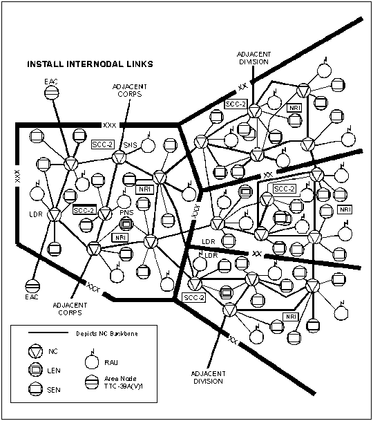
Figure C-1. MSE Network Architecture
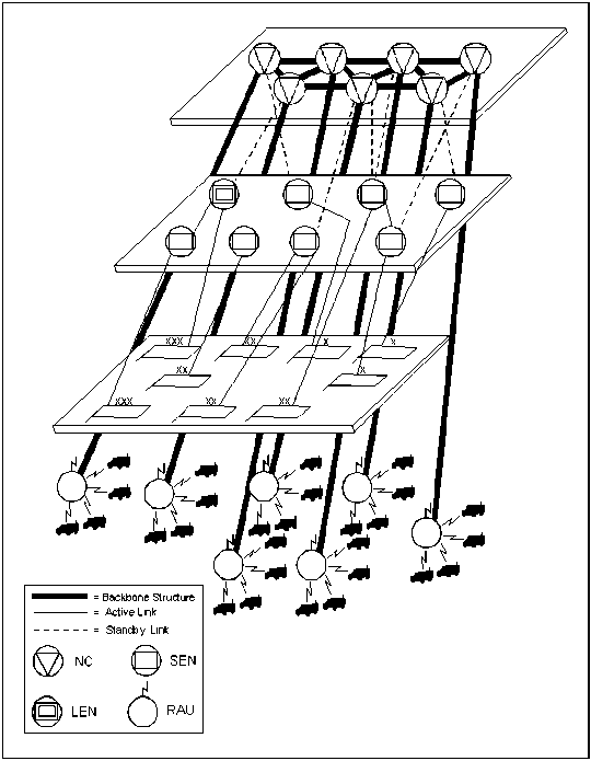
Figure C-2. MSE Architecture Layers
MSE TECHNIQUES
C-5. MSE is a digital telecommunications system, which provides tactical voice and data communications. MSE provides digital voice, data, and facsimile communications on an automatic, discrete address, fixed directory basis using flood search techniques. Flood search techniques initiate each call over multiple routes and establishes the connection over the optimum route based on current traffic within the network. This technique avoids heavily used routes, bypasses failed routes or nodes, and readily adapts to conditions of overload or blockage. Flood search routing ensures that trunks are not assigned and connected until after the called party has been located and an acknowledgment received.
EMPLOYMENT
C-6. MSE can support a corps of five divisions in an area of operations up to 15,000 square kilometers by a grid network. For a division, the MSE grid consists of four to six NCs that make up the backbone of the network. For the corps, the grid consists of 22 NCs. Throughout the maneuver area, subscribers connect to the SENs/LENs by radio or wire. These extension nodes serve as local call switching centers and provide access to the network by connecting to the node center switch (NCS) at the NC.
Components
C-7. MSE has various integrated components to ensure mobile and static subscribers have voice, data, and facsimile capabilities. These capabilities support the subscribers' communications no matter where they are in the MSE grid network. MSE components include-
- NC.
- LEN.
- SEN.
- RAU.
- SCC-2.
- ISYSCON.
- LOS radio system (components of the switches).
- MSRT.
- Subscriber terminals.
- Force entry switch (FES).
NC
C-8. NCs provide key switching, traffic control, and access points for MSE. After determining the coverage area, NCs are allocated to establish a corps MSE grid network. NCs are primarily linked by LOS radios to provide communications throughout the system via the NCS. TACSAT and tropospheric scatter (tropo) are connected to the NCs by cable. If one NC is disabled, the system automatically routes communications through another NC.
C-9. The NCS serves as an access point for LENs, SENs, RAUs, SCC-2s, and ISYSCON. The NCS is the hub of the MSE node and provides network interface for subscriber access elements. Figure C-3 shows internodal connectivity. It provides automatic subscriber finding features that allow permanent address assignment and removes the requirement of knowing where the subscriber is physically located. It is contained in three S-250 shelters: the switching group, the operations group, and the node management facility (NMF).
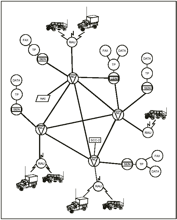
Figure C-3. Internodal Connectivity
LEN
C-10. The LEN provides wired communications for personnel at large CPs. A LEN enables up to 164 wired subscribers to communicate freely through the large extension node switch (LENS) using automatic flood search routing. Subscribers have access to the NCs and to the rest of MSE via LOS radios that connect to the LENS by cable or SHF radio systems.
C-11. The LENS provides automatic subscriber finding features that allow permanent subscriber address assignment. It also removes the requirement of knowing where the subscriber is physically located. It consists of two S-250 shelters containing a switching group and an operations group. The LENS is configured basically the same as the NCS. The differences include terminating trunks. The LEN is not a tandem switch because it is not used primarily as an intermediate switching point between other switching centers. The LENS supports flood search routing. The switching group provides the external interface, circuit switching, and associated functions. The operations group provides central processing and operator interface functions. Some LENSs enable CNR users to enter the MSE network and provide access to commercial networks.
SEN
C-12. The SEN supports the communications needs of smaller CPs. The AN/TTC-48(V)1 can support 26 wired subscribers and the (V)2 can support 41 subscribers. Users have access to NCs and to the rest of MSE via LOS radios that connect to the small extension node switch (SENS) by cable or SHF radio systems.
C-13. The SEN also provides automatic subscriber finding features when connected to an NCS or a LEN. These features allow permanent subscriber address assignment, and they remove the requirement of knowing where the subscriber is physically located. The SEN is in one S-250E shelter mounted on an M-1097 HMMWV. The SEN consists of switching, multiplexing, and COMSEC equipment. It is available in two versions: (V)1 and (V)2. Both versions provide two commercial office interfaces and a secure digital net radio interface (SDNRI) using the SDNRIU, KY-90. The SENS interfaces with the NCS and LENS directly via CX-11230A/G cable, LOS multichannel radio, or multichannel TACSAT.
RAU
C-14. The RAU picks up signals from the MSRT and sends them to the NCs. When a mobile user moves out of range of one RAU and into another, the telephone service automatically transfers to the next (new) and into the range of another RAU, thus providing automatic reaffiliation. Any subsequent calls will be placed through the system via the new RAU ensuring full and continuous functional affiliation throughout the area of operations.
C-15. The RAU, AN/TRC-191, is a fully automatic radio interface for MSRT subscribers. The RAU connects directly to the NC by cable or remotely via LOS radio. The local RAU provides radio coverage within the general area of the parent NCS by automatically establishing secure, full-duplex communications between the MSRT and the MSE network through the parent NCS. Figure C-4 shows how the MSRT (AN/VRC-97) accesses the system through the RAU. MSRTs can receive or send voice, facsimile, or data traffic. The planning range between the MSRT and RAU is 15 kilometers (9.3 miles). Terrain and weather will affect the actual range.
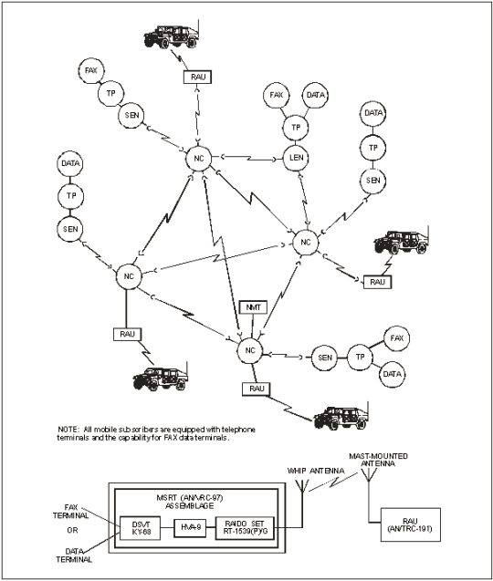
Figure C-4. Mobile Subscriber Interface
C-16. RAUs are used in local and remote configurations. However, it does not mean both RAUs cannot be remoted; it depends on the availability of an LOS assemblage. Because RAUs constantly emit marker beacons declaring availability to affiliated MSRTs, those RAUs closest to the forward edge of the battle area must use EP techniques to mask the emitter from the opposing force.
C-17. Deployment of the LOS assemblages must be considered to minimize the radio signature of the node. As an internodal link, the LOS(V)3 can deploy on hills up to 400 meters from the node via CX-11230A/G cable. If the distance exceeds 400 meters, the SHF radio link can be used up to 10 kilometers (Figure C-5). SHF radio distribution to the NCs and LOS assemblages allows for remoting 50 percent of the radio links.
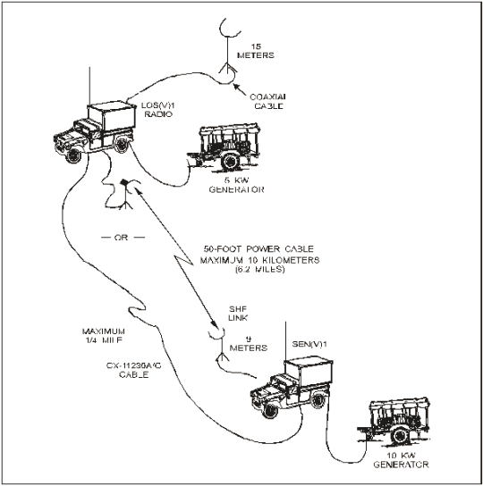
Figure C-5. SHF Radio Link
SCC-2
C-18. The existing MSE SYSCON capability is the SCC-2, AN/TYQ-46(V). It monitors, manages, and configures the MSE network (voice and data) for optimum communications.
C-19. The SCC-2 is an integrated, computerized communications control system that provides automated, near-real-time system control to support planning, configuring, reconfiguring, and monitoring the operation and movement of MSE assets. The SCC-2 normally connects to an NCS or LENS using CX-11230A/G pulse code modulation cable.
C-20. The SCC-2 comes in two versions: (V)1 and (V)2. Version 1 at corps consists of three shelters: one technical and two management/planning shelters. Version 2 is a stand-alone workstation for the corps area and support signal battalions. The SCC-2 at division consists of two shelters: one technical and one management/planning.
C-21. The technical shelter contains a network management center workstation and a technical workstation that provides a near-real-time graphic display of the MSE network. The network management center monitors and controls the TPN. The primary function of the technical workstation is to monitor and assign management functions. The network planners working inside the management/planning shelter complete the following functions:
- Deployment management.
- SCC-2 supervision and management.
- Boundaries management.
- COMSEC key management.
- Very high frequency (VHF) management.
- UHF/SHF management.
- Subscriber database management.
- Message management.
C-22. The management/planning shelter houses two system management workstations. These workstations provide a near-real-time graphic display of the MSE network and the automated tools necessary to create and change databases required for MSE operations.
C-23. The network planning tool (NPT) with its planning and management functions supports the SCC-2. The NPT provides improved NPE and operational automated information management capabilities. The enhanced NPE and operational functions of the NPT include-
- Environmental parameters.
- Digitized mapping.
- Radio/antenna system engineering.
- Terrain analysis profiling.
- System asset placement.
- Frequency assignment management (VHF, UHF, SHF).
- Team information.
- One-on-one interference analysis.
- Electronic warfare threat analysis.
- Subscriber list management.
- Word processing program.
- Spreadsheet program.
- E-mail program.
- Packet network monitoring.
C-24. The SCC-2 includes the following functional software tools:
- NPE for MSE assets.
- Battlefield spectrum management.
- MSE WAN management.
- System administration.
- E-mail.
ISYSCON
C-25. The ISYSCON is a suite of hardware and software giving the G6 and staff the automation capability to engineer, plan, and operate all communications systems including MSE. It enables the commander to interact with ABCS by exchanging common battle command information with the force commander and his staff and by exchanging communications information with maneuver force signal officers. The ISYSCON uses common hardware and software (CHS) for its workstations. ISYSCON provides the tools to perform the information management process by automating the following functions:
- Network planning and engineering (NPE).
- WAN management.
- Mission plan management.
- Battlefield spectrum management.
- COMSEC management.
- System administration.
- LAN management.
C-26. The ISYSCON program will field the system in a variety of configurations. The ISYSCON(V)1 will consist of two servers, four workstations, and ten remotes. The ISYSCON(V)1 will reside at the corps signal brigade and the division signal battalions. The ISYSCON(V)2 will consist of two servers, two workstations, and five remotes. The ISYSCON(V)2 will reside at the corps area signal battalion. The ISYSCON(V)1 will replace the SCC-2.
LOS RADIO SYSTEM
C-27. The LOS radio system consists of versatile links that connect all NCs in a grid network and provides automatic switched services to all wire and mobile subscribers. This radio grid delivers wireless communications to areas covering thousands of square kilometers. The LOS radio system, AN/TRC-190(V), has four versions.
C-28. The AN/TRC-190(V)1 is an LOS multichannel radio terminal. It provides point-to-point UHF radio links using the AN/GRC-226(P) radio set between various nodes of the MSE system. If the AN/TRC-190(V)1 has an AN/GRC-224(P) radio set installed, it can provide a short-range and a point-to-point SHF radio link. The SHF radio functions as a short-range, down-the-hill (DTH) radio providing a low signature connection between the sheltered CP site and the more exposed LOS terminal site. Each radio link supports a single, full-duplex, group-level connection and a single digital voice orderwire (DVOW) channel. The (V)1 is equipped with one AB-1339 mast with Band I and Band III antennas. The planning range of the UHF radio is 40 kilometers (28 miles). The (V)1 typically deploys with the SENS or remote RAU.
C-29. The AN/TRC-190(V)2 is an LOS multichannel radio terminal. It provides point-to-point UHF radio links using the AN/GRC-226(P) radio set between various nodes of the MSE system. If the AN/TRC-190(V)2 has an AN/GRC-224(P) radio set installed, it can provide a short-range and a point-to-point SHF radio link. The SHF radio set operates in tandem with the primary UHF radio link. Each radio link supports a single, full-duplex, group-level connection and a single DVOW channel. The (V)2 is equipped with two AN/GRC-226(P) radio sets (one on-line and one spare) and one AB-1339 mast with Band I and Band III antennas. The planning range of the UHF radio is 40 kilometers (28 miles). The (V)2 typically deploys as an analog interface to North Atlantic Treaty Organization (NATO) forces.
C-30. The AN/TRC-190(V)3 is an LOS multichannel radio terminal. It provides point-to-point UHF radio links using the AN/GRC-226(P) radio set between various nodes of the MSE system. If the AN/TRC-190(V)3 has an AN/GRC-224(P) radio set installed, it can provide a short-range and a point-to-point SHF radio link. The SHF radio set operates in tandem with the primary UHF radio link. The SHF radio functions as a short-range radio link providing connectivity for CPs. Each radio link supports a single, full-duplex, group-level connection and a single DVOW channel. The (V)3 is equipped with four AN/GRC-226(P) radio sets (two on-line and one spare) and three AB-1339 masts with two Band I and two Band III antennas. The planning range of the UHF radio is 40 kilometers (28 miles). The (V)3 typically deploys with the NCS and is a radio relay.
C-31. The AN/TRC-190(V)4 is an LOS multichannel radio terminal. It provides point-to-point UHF radio links using the AN/GRC-226(P) radio set between various nodes of the MSE system. Each radio link supports a single, full-duplex, group-level connection and a single DVOW channel. If the AN/TRC-190(V)4 has an AN/GRC-224(P) radio set installed, it can provide a short-range, DTH, and a point-to-point SHF radio link. The (V)4 is equipped with two AN/GRC-226(P) radio sets (two on-line) and two AB-1339 masts with Band I and Band III antennas. The planning range of the UHF radio is 40 kilometers (28 miles). The (V)4 typically deploys with the LENS.
MSRT
C-32. MSE network users gain mobile access using the MSRT (AN/VRC-97) through the RAU by affiliating onto the network. MSRTs can receive or send voice, facsimile, or data traffic. The planning range between the MSRT and RAU is 15 kilometers (9.3 miles). Terrain and weather will affect the actual range.
SUBSCRIBER TERMINALS
C-33. MSE users initiate and end all communications by using subscriber terminals. The terminals are described below.
C-34. The DNVT, TA-1035/U, provides voice and data access to the MSE network. Its features include-
- Handset.
- Keypad.
- Digital transmission (16 kilobits per second (kbps)).
- Four wire with data port to interface with computer/facsimile (FAX).
- Compatibility with other terminals.
C-35. The digital subscriber voice terminal (DSVT), KY-68, provides secure access to MSE for all mobile or fixed subscribers. It functions closely to the DNVT, and its features are the same.
C-36. The FAX terminal, AN/UXC-7, transmits critical information such as overlays, diagrams, and handwritten messages over the system in seconds. Ruggedized versions are usable with both DNVTs and DSVTs. Its features include-
- Digital transmission (16 kbps).
- Black and white copy with eight shades of gray.
- Standard issue paper usage.
- Embedded memory with burst transmission.
- NATO interoperable.
FES
C-37. The FES combines the essential functions of the NCS/LEN/NMF shelters and a RAU in one shelter. The FES combined with an LOS AN/TRC-198 comprises the CCP. The connections between the FES and the LOS are by cable since no SHF is supplied. The FES has packet switch capability, but it has no gateway function. Therefore, it has no direct connections to adjacent corps or EAC. The FES can be operator-controlled outside the shelter by a dismountable node management facility (DNMF) remote terminal.
C-38. The FES provides full flood search capability via the downsize routing subsystem, an SHF interface capability, and a DSVT in the truck. The line termination unit provides modem/multiplex functions for the local subscriber interface and is equipped with a rear terminal board to permit direct connections instead of the J-1077.
C-39. The LOS AN/TRC-198 is similar to an LOS(V)3, except that the LOS AN/TRC-198 UHF radios operate on three separate link connections to the FES (no multiplex) and all links operate on either band.
MSE RANGE EXTENSION
C-40. The corps signal brigade has a range extension company that allows the grid network to flex with the dynamics of rapidly changing tactical operations. Range-extension packages are organic to this company and deploy according to METT-TC needs. The range extension company has one TACSAT platoon and four tropo platoons. Range-extension packages have two transmission media forms: TACSAT and light tropo. Both are vehicular mounted, air transportable, and have multichannel capability. Satellite availability determines the TACSAT range. The tropo range is about 160.9 kilometers (100 miles).
C-41. Basic asynchronous transfer mode (ATM) Technology
C-42. ATM technology provides a highly efficient communications system for high-speed data switching. This capability transmits voice, video, and data in a single communication link. Figure C-6 shows the basic ATM switch technology. The system can also transmit still photography, images, and graphics.
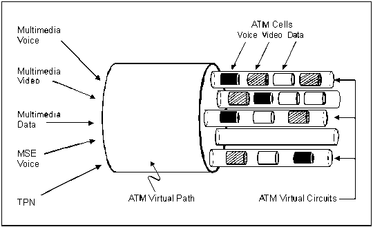
Figure C-6. ATM Switch Technology
C-42. The ATM basic technology concept involves using a virtual path identifier and a virtual circuit identifier. These identifiers are used for ATM address assignment. The path identifier directs the data to the correct receiver, and the circuit identifier identifies the different cell streams within a transmission. Virtual circuits are one-way ATM connections from source to destination, which means that two connections are required for full-duplex (two-way) communications.
HIGH-SPEED MULTIPLEXER (HSMUX) CARD
C-43. The HSMUX card enhances the capabilities of the communications modem (CM) and can terminate data rates higher than 512 kbps. The HSMUX provides up to four additional ports within a standard digital transmission group. Depending on the configuration, these ports can provide up to four synchronous data circuit-terminating equipment (DCE) RS-422 (balanced) serial data links at 64, 128, or 256 kbps. Figure C-7 shows the HSMUX SEN configuration.
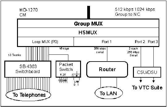
Figure C-7. HSMUX SEN Configuration
C-44. The HSMUX performs an inverse multiplexer function by taking the aggregate port rate (256 kbps) of each serial data circuit (router) and breaks it into individual 16 or 32 kbps channels on the digital transmission group. Figure C-8 shows the inverse multiplexer.
C-45. The HSMUX card replaces the A10 multiplexer/demultiplexer card in the CM, and it provides four additional serial ports. The back plane of the A10 card is not wired for access outside the CM. The individual Diphase Loop Modem-A (DLPMA) card provides access to the patch panel for the original SEN trunks. A high-speed balanced interface card (HSBIC) provides access to the new high-speed ports without modifying the CM or the line terminating unit. The HSBIC replaces one of the DLPMA cards in the CM. The HSBIC terminates two of the four HSMUX ports and extends them to the patch panel instead of the four voice trunks. These serial circuits are then patched over to the line side of the patch panel so the circuit can be extended over 26-pair to a J-Box. Figure C-9 shows the HSMUX/HSBIC SEN signal flow.
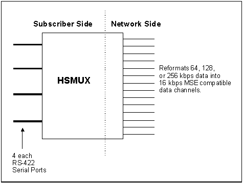
Figure C-8. Inverse Multiplexer
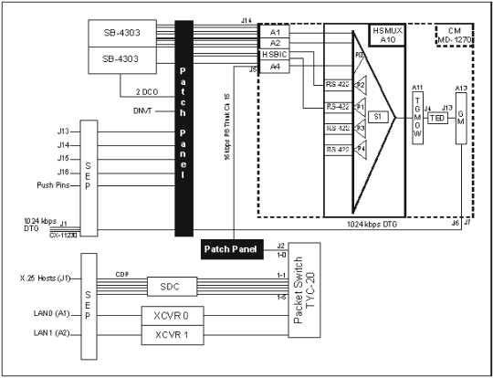
Figure C-9. HSMUX/HSBIC SEN Signal Flow
The HSMUX enhancement provides standard MSE connectivity and two high-speed ports that terminate in a router and a channel service unit/data service unit used for serial video teleconferencing. The router and the service units are safeguarded by a universal power supply. This power supply provides battery backup and acts as a direct current inverter, drawing power off the vehicle's 24-volt electrical system. Figure C-10 shows the enhanced SEN configuration signal flow.
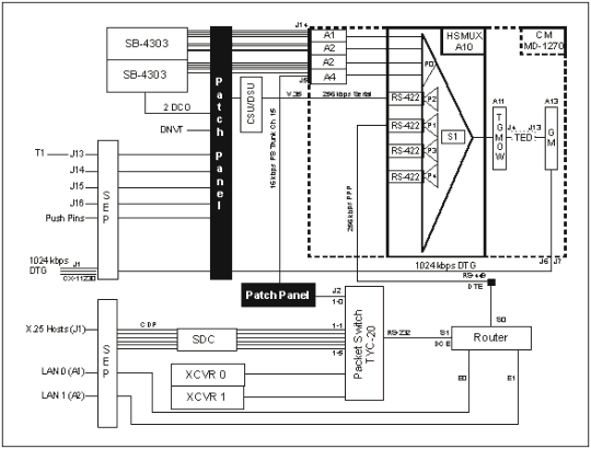
Figure C-10. Enhanced SEN Configuration/Signal Flow
|
NEWSLETTER
|
| Join the GlobalSecurity.org mailing list |
|
|
|