Appendix B
LAN Troubleshooting Guide
This appendix provides the user a guide for troubleshooting faults before contacting the G6/S6 for assistance.
Physical Fault Isolation
B-1. Users are responsible for troubleshooting their information systems using diagnostic software and BIT equipment. The user will follow certain steps in determining fault isolation as hardware, network, or software related.
ROUTER-BASED ARCHITECTURE
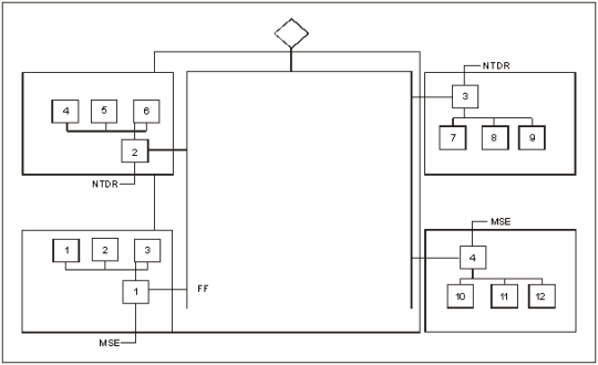
B-2. LAN troubleshooting consists of isolating and repairing a LAN failure within the CP. With the tools provided, the SA/NA can find most LAN faults. Determining which devices on the LAN are reachable can easily identify most failures. Figure B-1 shows the router-based diagram. If a LAN monitoring device is connected at point DD and-
- Only devices 1 through 6 are reachable, then a fault exists in the LAN B segment between router 2 and router 3.
- All devices are visible except router 2 and devices 4 through 6, then either the LAN segment connecting router 2 to LAN B is bad or router 2 is not functioning.
B-3. Following this logic, physical LAN and device faults can be isolated quickly.
SWITCHED-BASED ARCHITECTURE
B-4. Fault isolation is a more difficult task. Figure B-2 shows the switch-based diagram. If a LAN monitoring device is connected at point FF and-
- Only devices 1 through 6 are reachable, then a fault exists in the central router switch 3 or switch 4 or any of the physical connections to these devices.
- All devices are visible except switch 2 and devices 4 through 6, then either the LAN segment connecting switch 2 to the LAN is bad, or the central router is not configured properly.
B-5. The SA/NA connects to these devices and tries to isolate the fault. In a switched-based architecture, the physical LAN and device faults can be isolated, but not as quickly.

Figure B-1. Router-Based Architecture

Figure B-2. Switched-Based Architecture
WORKSTATION FAILURES
B-6. If only one workstation is experiencing difficulty, the problem is probably a software failure on that machine. Further troubleshooting is required to verify the fault. Each workstation has maintenance and diagnostic (M&D) software installed for troubleshooting the systems software. Troubleshoot the system with the M&D software IAW the software section, the BFA users manual, or if needed, guidance from the G6/S6.
WAN Failures
B-7. If all the devices on the LAN can communicate locally but cannot send messages across the WAN, it is probably down. If the users identify this problem first, they should contact the SA/NA for network status. The SA/NA should check the current status of the network. If the WAN is down or is not accessible, the SA/NA should notify the users immediately. The C2 systems communicate outside of the TOC via the US message text format (USMTF) and/or VMF messages sent by the sendmail program. If the message cannot be delivered, sendmail places the message in a queue. The software is adversely affected as the sendmail queue fills with undeliverable messages.
Intermittent Problems
B-8. Intermittent or sporadic LAN problems are usually caused by an improper LAN configuration, marginal piece of hardware, improper LAN grounding, or marginal WAN links. Since the problems are difficult to isolate, the maintainer should-
- Check the WAN status.
- Ensure no noise is being induced on the WE-16 X.25 connection by an improperly placed generator cable.
- Check the physical LAN for improper physical connections (such as branches, more than two terminators, LAN too long, or more than 30 devices connected.)
B-9. Improperly connected LANs may continue to function in a degraded mode, concealing the problem under certain conditions. Carefully examine the LAN for loose connections or damaged cables. Shake cables, if possible, to determine if the problem gets worse.
USER MAINTENANCE
B-10. The user of each system is responsible for performing preventive maintenance checks and services (PMCS) IAW applicable technical manuals. He is responsible for troubleshooting problems or failures before requesting assistance from the organizational maintainer. The tools identified below are available to assist the user during PMCS and troubleshooting.
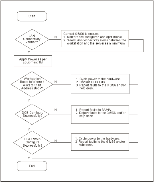
B-11. Each system's software package includes an M&D program, which runs when the system is powered up. Figure B-3 shows startup troubleshooting procedures. These diagnostic routines identify failed components and/or open connections. When a failure is noted, the user troubleshoots IAW with instructions presented by the diagnostic program and IAW the appropriate technical manual.

Figure B-3. Startup Troubleshooting Procedures
B-12. Each device has specific diagnostic procedures available when a failure is suspected. The user performs these procedures IAW the troubleshooting instructions in the technical manuals.
B-13. The technical manual contains troubleshooting instructions to be used when diagnostic procedures cannot run or fail to locate the problem.
HARDWARE (HOSTS) TROUBLESHOOTING
B-14. Users are responsible for troubleshooting hardware faults by using the appropriate technical manuals.
B-15. The user determines the information system to be nonoperational and notifies the mission applications administrator of a system failure. Using diagnostic software and BIT equipment, the user and mission applications administrator will try to determine whether the failure is hardware, network, or software related. For software related problems, the user will reload the software and return the system to operation. The user will replace LRUs and turn in failed LRUs through the forward support company. If the user cannot fix the problem or determines the problem to be a network/communication-related failure, he will contact the G6/S6 section.
NOTE: The user and the mission applications administrator will assist in the troubleshooting process and reloading of software.
Unit-Level Maintenance
B-16. The user requests assistance from the G6/S6 section when he cannot diagnose or correct a problem with his device. The SA/NA is skilled in using M&D software and has the equipment needed to check cables and connectors for serviceability.
B-17. The G6/S6 will verify the status of the system by using troubleshooting procedures to identify the failure as a network, software, or hardware problem. When the troubleshooting is complete, the G6/S6 assists the user in restoring the system by reinstalling system/application software or by identifying the malfunctioning LRU. If the G6/S6 identifies the problem to be an unserviceable LRU and cannot repair it, the G6/S6 will turn the unserviceable LRU into the forward support company. If the problem is software related and reinstalling the application does not fix it, he will contact the supporting software subject matter expert.
Software Troubleshooting
B-18. Generally, software is system specific and supported by each BFA. For example, the division artillery provides software support for AFATDS and the Military Intelligence Battalion provides software support for ASAS, and so on. The contractor or Army Communications-Electronics Command provides additional support. The user troubleshoots his software, but may require assistance from the G6/S6. Refer to Figure B-4 and the software manual for troubleshooting procedures.

Figure B-4. Software Troubleshooting Procedures
NETWORK TROUBLESHOOTING
B-19. The potential for connectivity and performance problems is high, and the source of such problems is often elusive. Failures are characterized by certain symptoms. These symptoms may be general (such as clients being unable to access specific servers) or more specific (routes not in routing table). Each symptom can be traced to one or more problems or causes by using specific troubleshooting tools and techniques. Once identified, each problem can be remedied by implementing a solution consisting of a series of actions.
B-20. It is always easier to recover from a network failure if you are prepared ahead of time. Table B-1 gives a list of network preparation questions. To see if you are prepared for a network failure, answer the questions. If you can answer yes to these questions, your chances of recovering from a failure are improved.
Table B-1. Network Preparation Questions
|
QUESTION |
YES |
NO |
|
Do you have an accurate physical and logical map of your internetwork? |
||
|
Does your organization or department have an up-to-date internetwork map? |
||
|
Does the map outline the physical location of all the network devices and how they are connected? |
||
|
Does the map give network addresses, network numbers, subnetworks, and so forth? |
||
|
Do you have a list of all network protocols implemented in your network? |
||
|
Do you have a list of network numbers, subnetworks, zones, areas, and so on that are associated with each implemented protocol? |
||
|
Do you know which protocols are being routed? |
||
|
Do you have a correct and up-to-date router configuration for each protocol? |
||
|
Do you know which protocols are being bridged? |
||
|
Are there any filters configured in any of these bridges, and do you have a copy of these configurations? |
||
|
Do you know all the points of contact to external networks, including any connections to the Internet? |
||
|
Do you know what routing protocol is being used for each external network connection? |
||
|
Do you have an established baseline for your network? |
||
|
Has your organization documented normal network behavior and performance so you can compare current problems with a baseline? |
GENERAL ETHERNET PROBLEMS
B-21. Table B-2 gives some general Ethernet problems and suggested solutions. These procedures will identify and correct some of the problems that a user may encounter.
Table B-2. Ethernet Troubleshooting
|
MEDIA PROBLEM |
STEPS |
SUGGESTED ACTIONS |
|
Step 1
Step 2 Step 3 Step 4 |
Use the show interfaces Ethernet EXEC command to determine the status of the routers Ethernet interfaces. Check cables for damage. Look for badly spaced taps causing reflections. If you are using 100BaseTX, make sure you are using category 5 cabling and not another type (such as category 3). |
|
|
Step 1
Step 2 Step 3 |
Use the show interfaces Ethernet command to check the rate Use a TDR1 to find any nonterminated Ethernet cables. Look for a jabbering transceiver attached to a host. (This may require a host-by-host inspection or using a protocol analyzer.) |
|
|
Excessive Runt Frames |
|
In a shared Ethernet environment, runt frames are almost always caused by collisions. If the collision rate is high, refer to the problem Excessive Collisions earlier in this table. If runt frames occur when collisions are not high or in a switched Ethernet environment, then they are the result of underruns or bad software on a network interface card. Use a protocol analyzer to try to determine the source address of the runt frames. |
|
Late Collisions |
Step 1
Step 2 |
Use a protocol analyzer to check for late collisions. Late collisions should never occur in a properly designed Ethernet network. They usually occur when Ethernet cables are too long, or when there are too many repeaters in the network. Check the diameter of the network and make sure it is within specifications. |
|
No Link Integrity on 10BaseT, 100BaseT4, or 100BaseTX |
Step 1
Step 2 Step 3 Step 4 |
Make sure you are not using 100BaseT4 when only two pairs of wire are available. Check for 10BaseT, 100BaseT4, or 100BaseTX mismatch (for example, a card different than the port on a hub). Determine whether there is a cross connect (for example, do not use straight through cables between a station and a hub). Check for excessive noise (see the problem Excessive Noise earlier in this table. |
|
NEWSLETTER
|
| Join the GlobalSecurity.org mailing list |
|
|
|

