Appendix G
Selecting Frequencies for Radio Multichannel Systems
G-1. Frequency Selection/LOS Multichannel
The method of frequency selection depends on the equipment and the configuration of the multichannel communications network. Much depends on the radio relay network. Is it a simple isolated system or a complex system? Are there more than two transmitters and receivers operating at the same location? Does the complex system have light and heavy traffic routes interconnecting and crossing of radio systems? These factors must be considered when selecting a proper, workable frequency assignment plan. Technical manuals covering that equipment describe the method used for each piece of equipment. This appendix covers the radio set, AN/GRC-103(V) band 1 since it is one of the current radios used with pulse code modulation (PCM) multiplexing equipment in radio relay systems. The frequencies used in this appendix will be those of the AFVGRC-103(V) (band 1220.0 to 404.5 MHz). MSE LOS multichannel is the newest system fielded. It uses the radio set, AN/GRC-226(V). Frequencies assigned for use are provided by automated spectrum management by the SCC.
G-2. Interference Between Transmitters and Receivers
The purpose of any frequency plan is to minimize the effects of mutual interference. With a radio set operating full duplex, the transmitting power is usually millions of times greater than the power of the receiver's signal. The receiver must be able to reject the transmitter signal and select the weak signal to which it is tuned.
To reject a transmitted signal, a receiver must be separated from the transmitter by so many channels according to the radio being used (see proper technical manual).
This separation is called a guard band. When using the AN/GRC-103(V), the transmitting frequencies at a station must be well separated from the receiver frequencies to guard against transmitter-to-receiver interference. This is done by setting up a frequency guard band of 16.5 MHz (33 channels) between the transmitter and receiver frequency.
The receiving frequencies at a station must be well separated from each other to guard against receiver-to-receiver interference. This is done by operating the receiver so at least three unused frequency channels (1.5 MHz) separate the operating frequency of any two receivers.
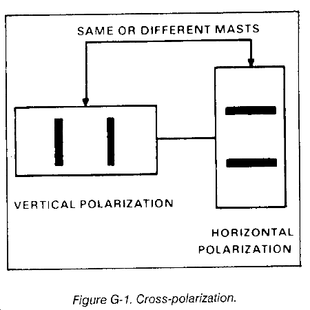
Two methods that reduce the required frequency separation between systems from 16.5 MHz (33 channels) to 5 MHz (10 channels) are cross-polarization and separate masts.
Sometimes antennas on neighboring masts may be cross-polarized to advantage. (loss-polarization is having one antenna polarized in one plane (horizontal or vertical) and the other antenna polarized in the other plane. Cross-polarization results in a greater isolation between antennas on the same mast or neighboring masts. It also permits the separation between transmitting and receiving frequencies on these antennas to be much smaller than with noncross-polarized antennas (Figure G-l).
In applicable systems, using separate masts for transmitters and receivers at a station reduces the transmitter-to-receiver interference at that station. This isolation can be further improved by using vertical polarization for one antenna and horizontal polarization for the other.
G-3. Two-Block Frequency Assignment Plan
The two-block plan is used for simple isolated systems. An isolated route is one which does not cross or connect with any other radio-relay routes. For example, a system may consist of two terminals and three repeaters (Figure G-2) with the radios operating between 220.0 and 404.5 MHz.
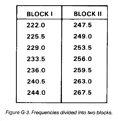
To set up a two-block plan, arrange the frequencies in numerical sequence (lowest to highest). Divide the available frequencies into two blocks that contain equal numbers of frequencies. Arrange them so each frequency in the first block may be paired with a frequency in the second block which is separated from the lower frequency (Block I) by at least 16.5 MHz (Figure G-3).
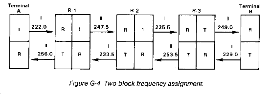
Assign transmitting frequencies beginning at terminal A by selecting a frequency from Block I and then from Block II (Figure G-3). Assign all transmitting frequencies in an A to B direction; then assign frequencies in the same manner from a B to A direction (Figure G-4).
Ensure to maintain the minimum required receiver-to-receiver separations at all sites where two or more receivers are located. In this case, it would be the three repeaters that would have to be checked for proper receiver-to-receiver separation. For this reason, frequencies from a specific block may not always be assigned consecutively.
The two-block plan can be used for a simple parallel system. Tangent systems from any site in the parallel system to other sites maybe established. This is possible because from any site in a paralleled system all transmitter frequencies are from one block, and the distant transmitter would transmit on a frequency from the opposite block. The two-block plan does not provide for alternate routing or operating among three different sites. When systems become too complex, the six-block ABM frequency assignment plan should be used.
G-4. Six-Block ABM Frequency Assignment Plan
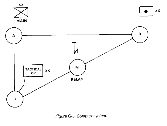
The six-block ABM plan is used for a complex system with two or more transmitters and two or more receivers at the same location (Figure G-5). (The letters A, B, and M have no significant meaning.)
The ABM plan divides a broad frequency assignment list (all or a large part of a band allocated) into six frequency blocks (or lists) of suitable widths. Frequencies obtained are divided equally among the six blocks. The basic planning is then done in terms of these blocks. Advantages of the six-block plan are shown below.
- Any station can be connected with almost any other station with minimum effect on the rest of the network.
- Planning is simplified.
- Quick frequency changes can be accomplished without any trouble.
- By dividing all frequencies into six blocks all assigned frequencies are usable.
- The necessary guard band between the transmitter and receiver frequencies is obtained.
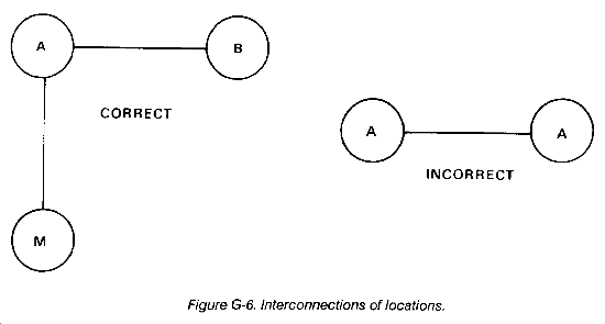
To use the ABM plan, designate each site with the letter A, B, or M. Be sure that sites with the same letter are not interconnected (Figure G-6). Following this rule, location A can establish radio links with locations B or M but not with another A.
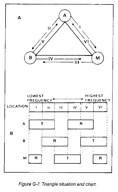
Considering all possible radio links, a triangle can be drawn as shown in Figure G-7A. Radio sets used in multichannel systems do not require transmitter-to-transmitter separation; therefore, all transmitter frequencies can be taken from the same block if necessary. Considering transmitter frequencies only, six groups or blocks of frequencies are required for the triangle. These blocks of frequencies are numbered I through VI. At location A, I and II are the transmitting frequencies and IV and V are the receiving frequencies.
To set up a system between A and M, the transmitter frequencies at A must be from Block I and the receiver frequencies at A must be from Block IV. Each system has a designated block from which the frequencies are taken (Figure G-7B). To set up a system from B to M, find the block where B transmits and M receives. In this case, it is VI.
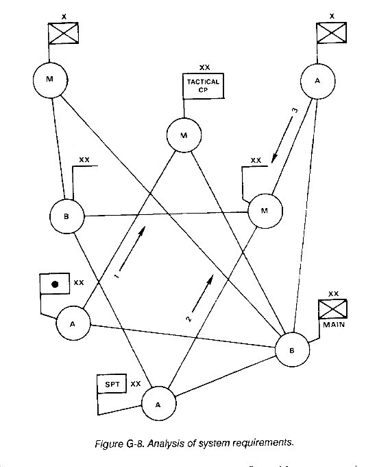
Six blocks of frequencies are required when considering the six transmitter frequencies from the triangle situation. The required separations between the blocks (the transmitter separation from receiver frequency by at least 16.5 MHz or more) are also considered. From the triangle situation to a more complex situation such as Figure G-8, it is necessary to determine the number of frequencies required in each block. To do this, the system requirements must be analyzed. (We no longer just divide the frequencies equally into the six blocks.)
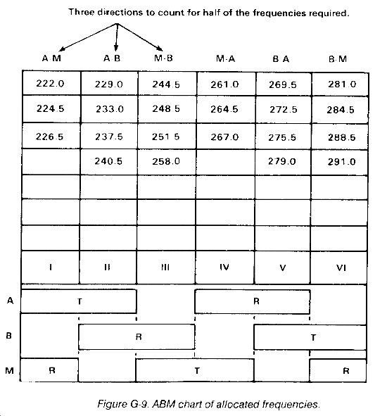
From Figure G-8, it can be seen that three transmitter frequencies are required for the A to M systems. Thus, a minimum of three frequencies are required in Block I for A to M. Continue the system analysis by counting Block II A to B frequencies, and then count Block III B to M frequencies. It is not necessary to determine the number of frequencies in Block IV, V, and VI because counting Blocks I, II, and III gives half the total number of frequencies for the entire system. Referring to Figures G-8 and G-9, note that in Block I a minimum of three frequencies is required in the A-M direction. Since frequencies on these systems are assigned in pairs, a total of at least three frequencies will be required in Block IV. Figure G-9 shows the requirements for the entire system.
When spare frequencies are assigned above the required number for the systems, the spare frequencies must be kept in numerical sequence with the other assigned frequencies and divided equally among the blocks. For example, if six spares are assigned, add them to the sequential listing, then add one more frequency to each block above the requirement (that is, Block 1, four frequencies; Block II, five frequencies). These spare frequencies may be used for displacement systems or additional systems above the amount estimated for the operation.
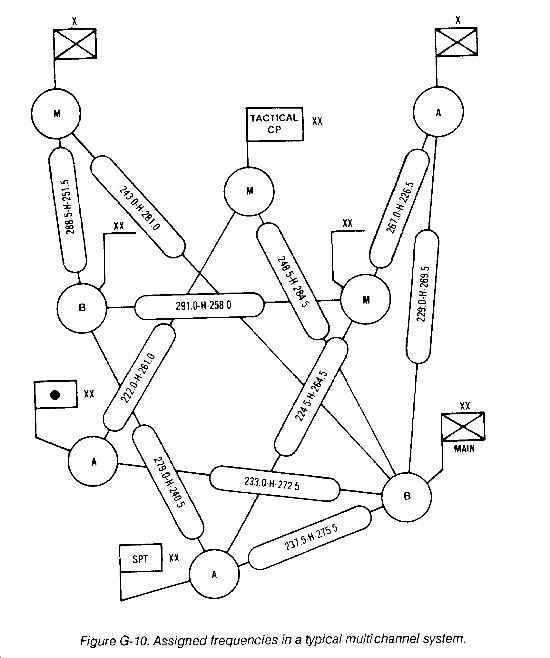
Frequencies may then be assigned to the system (Figure G-10). The transmitting frequency is always located next to the terminal or relay symbol. Refer to the analysis of system requirements to determine what direction each system is designated, such as A-M, A-B, or M-B; frequencies will be assigned in pairs for each system. For example, in Figure G-8, the first A-M system counted was from the division artillery to the division tactical air command (TAC). From Figure G-9, assign the first frequency in Block I (222.0 MHz) to division artillery for their transmit to TAC; at the same time, assign the first frequency in Block IV (261.0 MHz) as the transmit frequency from TAC to division artillery. If this procedure is followed exactly for each system, then transmitter-to-receiver separation will not be a problem. However, care must be taken at multichannel relays and terminals to ensure that receiver-to-receiver separations (1.5 MHz) are observed. Remember, the 1.5 MHz required separation pertains only to the AN/GRC-103 in these examples. For other radio sets, check the proper technical manuals.
The suggested method of assigning frequencies to radio relay systems is to assign frequencies in the priority used for establishing systems (command links, area links, logistic links, and so on). Figure G-10 shows all frequencies assigned to all systems with the proper guard bands.
G-5. Limitations of Frequency Assignment Plans
The frequency assignment plans that have been discussed have limitations. Generally, a two-block frequency plan will work for any simple isolated system regardless of the radio sets used. However, when frequencies are needed for complex systems with two or more transmitters and receivers at the same location, new problems arc often encountered.
The ABM plan is not the answer to eliminating all mutual interference problems encountered within all complex systems. When the frequencies used with some radio sets are broken down into blocks according to the ABM plan and other plans and the required frequency separations for the particular radio sets are maintained, problems with harmonics (multiple of a base frequency) are sometimes encountered. This problem can become even more complex in sophisticated frequency diversity troposcatter systems where the base band signal applies to two or more transmitters operating on different frequencies and receives on two or more receivers.
Each radio set has different sensitivity, selectivity, and other technical characteristics. When two or more systems use the same site, frequency separation between the transmit and receiver antenna on different masts becomes a critical consideration. A receiver acted on by certain base or harmonic frequencies from a transmitter located at the same location will encounter mutual interference. Because of this, a required frequency separation will have to be maintained between transmitters and receivers. Proper antenna orientation will have to be maintained between antennas. The required frequency separation between transmitters and receivers is not the same for all radio sets. When the receivers of some radio sets are located back-to-back as relay stations (repeaters), a different frequency separation may be required between the receivers than the frequency separation normally required when the receivers are located separately at the same location.
At times, it may be possible to use the same set of frequencies (from a block of frequencies) more than once within a particular complex communication system. Transmit frequencies that are the same or close to each other can sometimes be transmitted in opposite or near opposite directions. The effectiveness of this method will depend on the selectivity and sensitivity of the receivers used and the overall distance between them.
Generally, the only sure way to minimize the effects of mutual interference between transmitters and receivers is to follow the proper instructions on spectrum management and selection. General details are given in the proper technical manuals. This information will differ for each radio set.
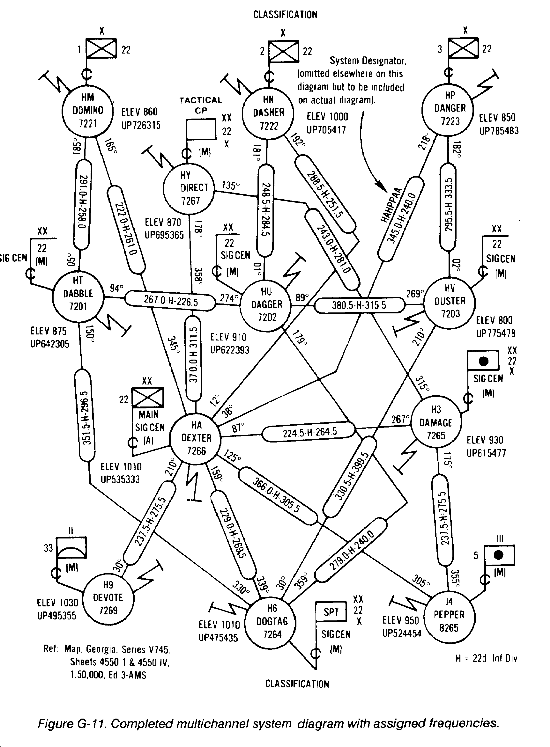
Figure G-11 shows a typical, completed, armored-infantry-mechanized (AIM) division multichannel system diagram with the assigned operating frequencies using the single ABM plan.
|
NEWSLETTER
|
| Join the GlobalSecurity.org mailing list |
|
|
|


