Appendix B
Interference Charts
B-1. Description and Use
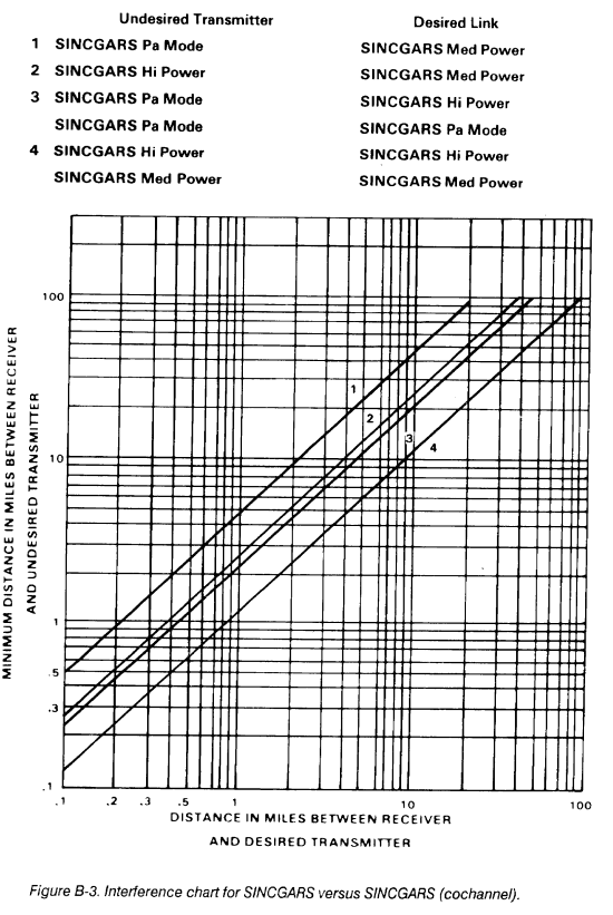
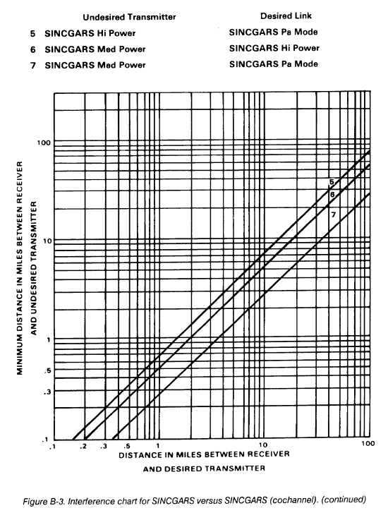
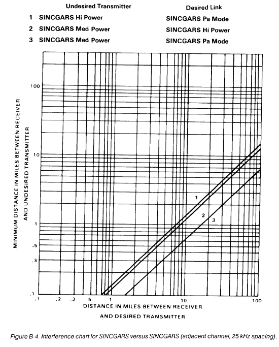
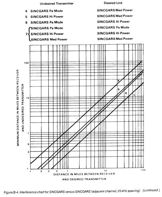
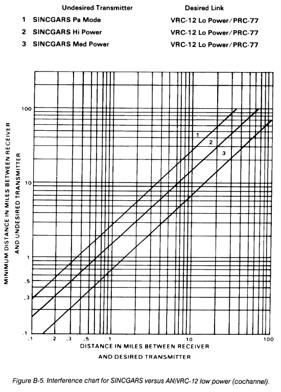
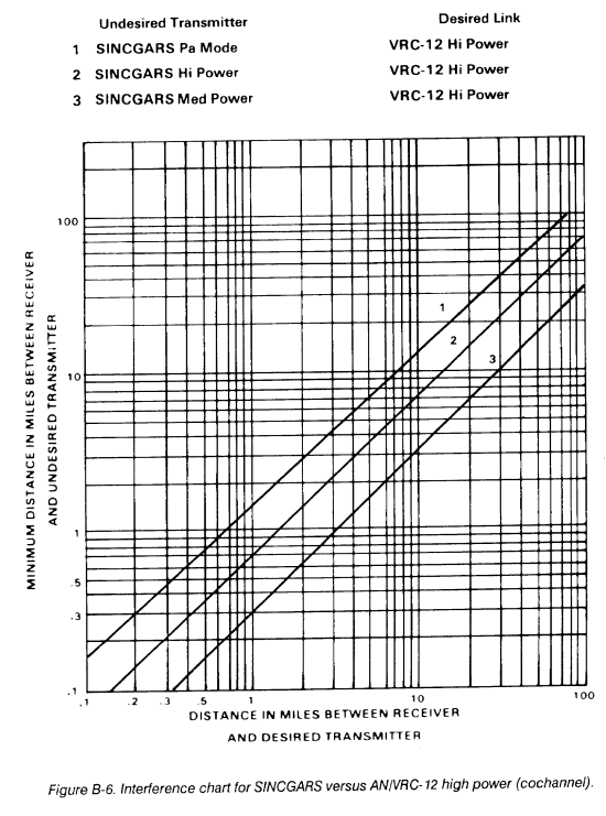
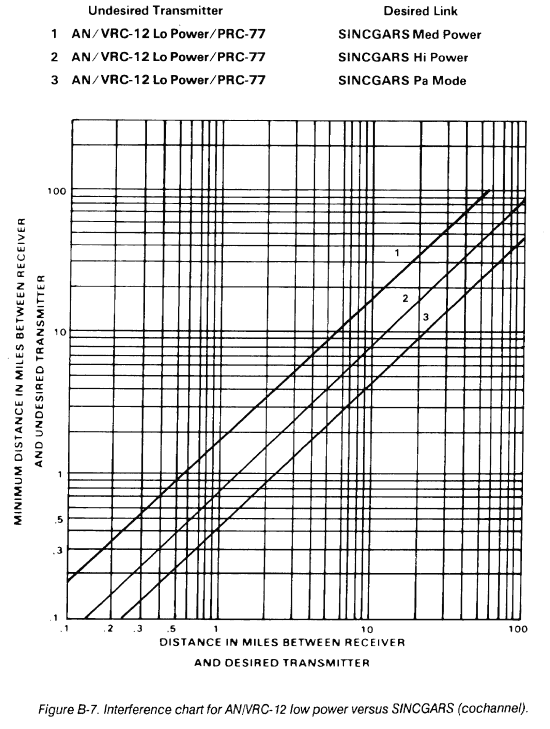
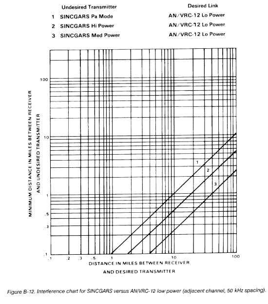
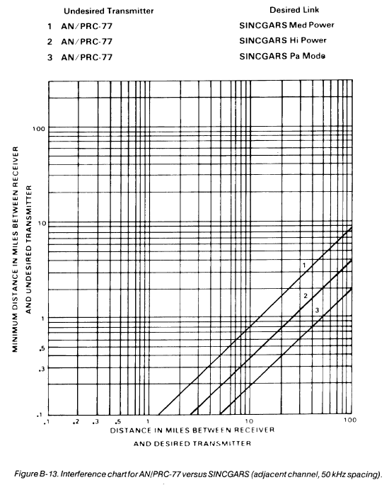
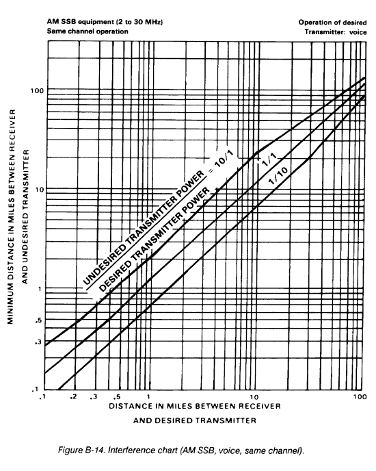
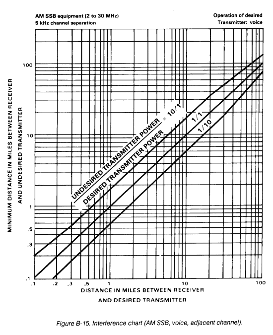
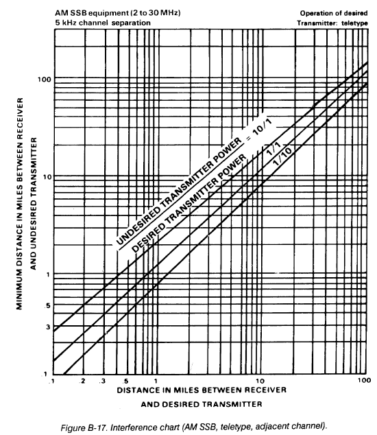
The interference charts in this appendix can be used in determining the distance separation required for cochannel and adjacent channel operation. Distance separation charts indicate the spacing needed between stations under different conditions of transmitter power output and types of emission. Interfering equipment is referred to as the undesired transmitter. Equipment interfered with is called the receiver and desired transmitter.
The following services are covered by the charts: AM SSB voice, teletype, and FM voice/data. Two charts are shown for each type of service. One chart is for use when the desired and undesired transmitters are on the same frequency; the other chart is used when the undesired transmitter is on an adjacent channel separated by the frequency indicated.
B-2. Sample Problem
Problem.
A desired transmitter and the desired receiver are operating an FM voice net on low power (8 watts) located 3 miles apart. What is the minimum distance a high power (35 watts) FM transmitter operating on the same frequency can be placed from the desired receiver without causing interference?
Solution.
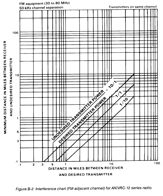
Since the desired signal is FM voice, the desired transmitter and receiver are operating on low power. The undesired transmitter is operating on high power and all are on the same frequency (Figure B-1).
The ratio of the undesired transmitter power to the desired transmitter power is 35 to 8 (about 4 to 1).
Enter the chart on the horizontal scale at the 3-mile point and extend a vertical line from this point until it meets the curve corresponding to a ratio of 4 to 1.
The curve corresponding to a ratio of 4 to 1 is not shown on the chart, but its position is found by interpolating between the 1 to 1 and 10 to 1 curves.
From this point, a horizontal line is drawn to the left until it intersects the vertical scale which indicates a distance of 6 miles.
Therefore, the minimum distance that the 35-watt undesired transmitter must be separated from the receiver is 6 miles.
NOTE: Interpolation is logarithmic between curves and gridlines.
B-3. Special Considerations
The adjacent channel charts are for 5-kHz separation (using 11 MHz frequency for SSB-voice AM equipment) and 50-kHz separation (using 53 MHz frequency for FM equipment). Any interfering equipment with less channel separation from the receiver than indicated in these charts results in a greater required distance separation from the desired receiver, and should be sited using the same-channel charts.
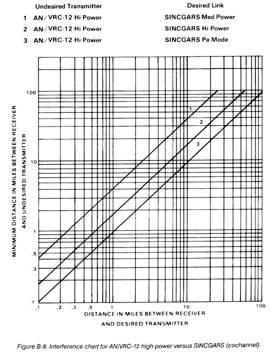
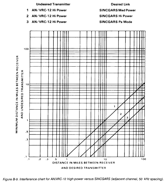
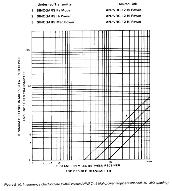
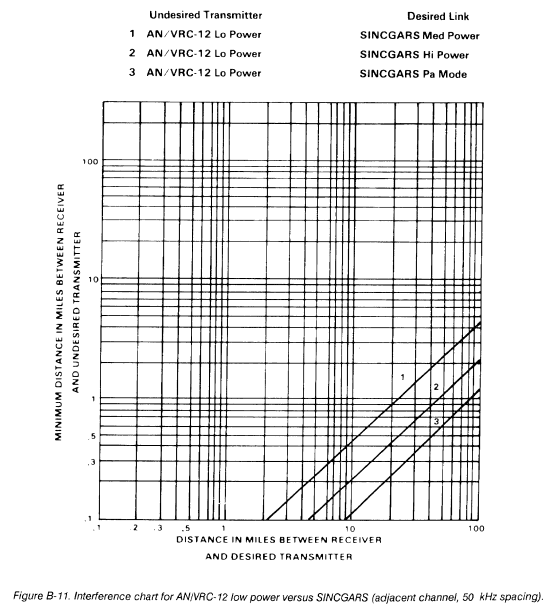
Figures B-1 and B-2 are charts for FM equipment based on the characteristics of the AN/VRC-12 series radio. These charts apply to equipment having similar characteristics as to maximum frequency deviation, selectivity, and frequency stability. Figures B-3 and B-4 are interference charts for SINCGARS versus SINCGARS. Figures B-5 through B-12 are interference charts for SINCGARS versus AN/VRC-12 series radio. Figure B-13 is an interference chart for AN/PRC-77 versus SINCGARS. Figures B-14 through B-17 are charts for SSB equipment based on the characteristics of the AN/GRC-106 radio set. These charts apply to equipment having similar characteristics as to modulation, selectivity, and frequency stability.
Only ground wave and direct wave transmissions were considered in preparing these charts. Propagation over a smooth spherical earth and using 15-foot vertical whip antennas were considered, based on cochannel signal-to-interference thresholds of AN/VRC-12, 6 dB; AN/GRC-106, SSB, 4 dB; and AN/GRC-106, teletype, 9 dB.
Mutual interference problems often result when FM transmitters operating on different frequencies are situated in the same locale. The problem can occur between AN/VRC-12 series radios and also between these radios and low power FM radios. These radio sets include the AN/PRC-25, AN/PRC-77, and the vehicular versions of these radios. These interference problems can be effectively reduced when the following basic assignment standards are followed.
When using the AN/VRC-12 series radio, avoid using frequencies that are harmonically related. For example, frequencies that are separated by exactly 5.75 or 23.00 MHz.
Do not assign frequencies to collocated nets that are on the order of the second harmonic. For example, the frequency setting of 30.00, 32.65, and 35.00 MHz will possibly interfere with a radio using 60.00,65.30, and 70.00 MHz, respectively.
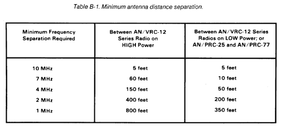
Observe the recommended minimum frequency versus distance restrictions given in Table B-1.
High frequency AM nets experience fewer interference problems than VHF, FM nets; however, some interference may result when these radios are operated in the same vicinity. Therefore, collocated HF nets should be assigned frequencies at least 100 kHz apart. RATT nets operating in the FULL-DUPLEX mode, with the transmitter and receiver on different frequencies, require a frequency separation of at least 400 kHz.
|
NEWSLETTER
|
| Join the GlobalSecurity.org mailing list |
|
|
|


