

CHAPTER 6
COMBAT TECHNIQUES OF FIRE
This chapter discusses the techniques and procedures of fire control, helicopter engagement, and firing the TOW under NBC and limited visibility conditions in a combat situation. These techniques and procedures greatly enhance the performance of the TOW weapon system in combat and increase its chances of survival.
Section I. FIRE CONTROL MEASURES
This section discusses fire control measures in combat to include target engagement determination procedures, the elements of fire commands, target tracking procedures, and target engagement procedures with the M220A1 and M220A2 TOW launchers.
6-1. TARGET ENGAGEMENT DETERMINATION
Mechanized units are trained to use terrain driving techniques to conceal movement, and drivers are taught to move vehicles quickly from one concealed position to another. TOW gunners and squad leaders must determine the range to a target and determine if the exposure time--the time a vehicle is in an opening between positions--is long enough to allow a missile to reach its target.
a. Determine if a Target Is Within Range. The TOW gunner or squad leader can use the nigh sight method or the binocular method to determine if a target is within range.
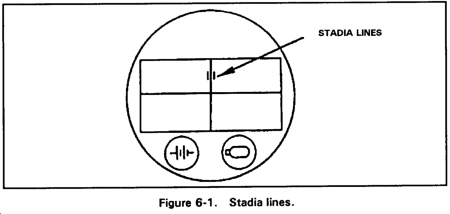
(1) Nightsight method. The reticle within the nightsight is marked with stadia lines on each side of the vertical crossline and just above the intersection of the vertical crossline and the horizontal crossline (Figure 6-1). Use these stadia lines to determine if a target is within range.
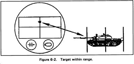
(a) Check to ensure the nightsight is in the narrow field of view.
(b) Look at the flank (broadside) of a target. If the ends of the target touch or extend beyond the stadia lines, the target is within range (Figure 6-2).
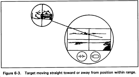
(c) If the target is moving straight or at an angle toward the position, use one-half of the stadia lines. If one side of the vehicle touches one of the stadia lines and the other side of the vehicle touches or extends beyond the vertical line of the crossline, the target is within range (Figure 6-3).
NOTE: When using the stadia lines to determine if a target is within range, keep two things in mind. First, the range is a rough estimate, based on the size of the target. A large vehicle may be out of range when the stadia lines show it to be in range. Second, the stadia lines are designed for a maximum engagement range of 3,000 meters.
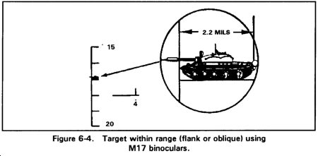
(2) Binocular method. Use the reticle in binoculars to determine if a target is within range by looking at the length, width, or height of the vehicle. Follow the same procedures when using the M17 and M19 binoculars, even though the reticles differ slightly. The M17 tick marks are only 1.7 mils long while the tick marks on the M19 reticle are 5 mils long (2.5 mils on each side of the horizontal and vertical scales).
(a) To determine if a target is within range at 3,000 meters based on the length of the target, place the length of the target on the vertical scale. If one-third or more of the vehicle extends beyond the tick mark, the vehicle is in range (Figure 6-4). A vehicle 6.5 meters long will measure about 2.2 mils at 3,000 meters and about 1.7 mils at 3,750 meters.
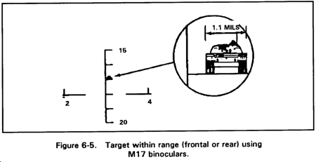
(b) To determine if a target is within range at 3,000 meters based on the width of the target, place the target on the small tick mark on the vertical scale. If the target covers two-thirds or more of the tick mark, the vehicle is within range (Figure 6-5). A vehicle 3.4 meters wide will measure 1.1 mils at 3,000 meters and .85 mils at 3,750 meters. (Most Warsaw Pact APCs are less than 3.4 meters wide and can be engaged at smaller mil values.)
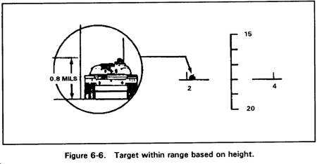
(c) To determine if a target is within range at 3,000 meters based on the height of the target, place the target on one of the tick marks on the horizontal scale. If the height of the vehicle is one-half or more of the height of one of the tick marks, the vehicle is within range. A vehicle 2.4 meters high (the size of most Warsaw Pact vehicles) will measure .8 mils at 3,000 meters and .6 mils at 3,750 meters (Figure 6-6).
NOTE: If the weapon system is in an elevated firing position or if the lower portion of the target vehicle is hidden by foliage or terrain, this method cannot be used.
b. Determine Exposure Time. The half-sight method of determining exposure time is based on a vehicle speed of 35 kph (the expected top vehicle speed of armored vehicles on level or gently sloping dry terrain).
(1) Daysight tracker method. Use the crosslines on the daysight tracker to determine the exposure time of a target.
(a) Place the crosslines of the daysight tracker on the center of the visible mass of the vehicle.
(b) If the area between the vertical crossline and the edge of the field of view in the direction of travel is clear of obstruction, the target is engageable (Figure 6-7).
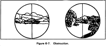
(c) If obstructions appear between the vertical crossline and the edge of the field of view, the time of exposure would not be long enough for the missile flight before the target moved out of sight (Figure 6-7).
(2) Nightsight method. The procedure to determine exposure time is the same for the nightsight as for the daysight tracker, except the nightsight must be set on narrow field of view.
(3) Binocular reticle method. Use the reticle in the binoculars to determine the exposure time of a target.
(a) Place the zero tick mark of the horizontal scale at the center of the vehicle.
(b) If the area between the vehicle and the 50-mil tick mark is clear of obstructions in the direction of travel, the target is engageable (Figure 6-8).

6-2. FIRE COMMANDS
The six elements of a fire command are alert, type of missile, target description, target direction, range, execution, and closing. Whether mounted or dismounted, the elements of the fire command are the same. (Figure 6-9 shows an example of a squad fire command.)

a. Alert. The first element of the fire command alerts the crew for an immediate engagement. The squad leader commands, "Squad," and the gunner begins observing the target area.
b. Type of Missile. Because a variety of TOW missiles are used and their capabilities vary, a particular type of missile must be specified. A TOW crew in battle will probably have a mix of different missiles and a wide variety of target arrays to engage (see Chapter 1, TOW missile types and configurations). For example, if the target is a BTR-60 or BMP-1, the squad leader may command, TOW 2; if the target is a T-80 with reactive armor, he may command, TOW 2B.
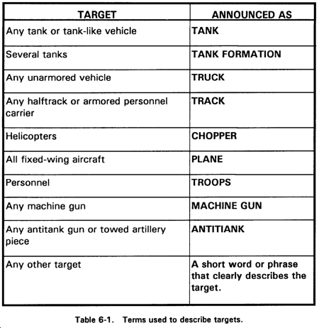
c. Target Description. The second element identifies the target for the gunner. If several similar targets are present, this element tells the gunner which target to engage first. Most targets can be described by using the terms listed in Table 6-1. Targets that are combinations of the ones listed in Table 6-1, such as a truck mounting a missile system, are identified by combining terms--for example, TRUCK MOUNTING ANTITANK. When the gunner sees the target, he announces, "Identified." If multiple targets appear, the commander may specify which target will be engaged by the gunner--for example, FIRST TANK or RIGHT TRACK.
d. Target Direction. If the target is moving, the direction of movement is given after the description to aid the gunner in locating the target. After the gunner is given the location of a target, he can search for the target in the direction of movement. The following methods are also used to help the gunner locate the target.
(1) Target reference point. A TRP is an easily recognizable feature or point on the ground (either natural or man-made) used for identifying targets and controlling fires. They can be used to designate targets for companies, platoons, sections, and individual weapons. They can also be used to designate the center of an area where the commander plans to distribute or converge the fires of all his weapons. TRPs are usually designated by the company commander or platoon leaders.
(a) Weapons will engage targets from different directions, so compass points (for example, north, east), rather than "right" or "left," are used when giving directions centered on a TRP.
(b) On the M901A1, the squad leader gives the direction to the target by using the periscope deflection scale. Deflection from the TRP can be estimated, or it can be measured using the binocular mil scale or the circular reticle on the wide field of view--for example, 5.5 degrees at 1,000 meters is about 100 meters, or 200 meters at 2,000 meters.
(2) Prominent features. The commander may give the distance and direction from a prominent feature--for example, FROM HILL SEVEN SIX TWO, LEFT TWO HUNDRED, or FROM BRIDGE, RIGHT FOUR HUNDRED.
e. Range. The range is given to help the gunner identify his target and to determine its engageability. The squad or section leader can determine the range to the target using the naked eye, binoculars (mil-relation formula), or reference materials (maps, range cards).
(1) Naked eye. One method for using the naked eye to determine range is the football field method. The squad or section leader counts in 100-meter increments, estimating the number of football fields that could fit between the firing position and the target.
(2) Binoculars. Binoculars and the mil-relation formula can be used to determine range. To use this method, the squad or section leader must know the width, height, or length of the target. He determines the width, height, or length with the binocular's mil scale; substitutes the mil-relation; and computes the range.
(3) Reference materials. Maps can be used to determine range by counting the grid lines between the firing position and the target or by adjusting from a known point. Range cards can also be used to determine the range to the target.
f. Execution. Two commands are necessary for execution: a preparatory command and a command of execution.
(1) AT MY COMMAND. This preparatory command warns the gunner not to fire until given the command of execution.
(2) FIRE. This is the only command of execution used to fire a missile.
g. Additional Commands. In addition to the six elements of the fire command, some other commands are needed.
(1) The command CEASE TRACKING or CEASE TRACKING, OUT OF ACTION is issued after seeing the round detonate or when the squad or section leader wants to halt firing.
(a) CEASE TRACKING tells the crew the squad or section leader intends to stay in position and engage another target immediately or when one appears.
(b) CEASE TRACKING, OUT OF ACTION tells the crew the squad or section leader intends to move to another position.
(2) To determine the method of engagement, the section leader (or above) selects a fire pattern depending on the opposing force's formation. The section leader directs, FRONTAL, DEPTH, or CROSSFIRE, when the gunner is faced with multiple targets.
(3) When the target is identified, the gunner announces, "Identified."
(4) If the gunner cannot see the target, he announces, "Lost."
(5) If the gunner cannot identify the target, he announces, "Cannot identify."
(6) The loader announces, "Backblast clear," before the command of execution is given.
h. Repeating Commands. When a crew member fails to hear or understand any element of a fire command, he announces the element in question. For example, if the gunner asks, "Location?" the squad leader repeats the location element such as, "From hill seven six two, west two hundred."
i. Correcting Errors. To correct an error in a fire command, the squad leader announces, "Correction," and corrects only the element in error. He completes the command by announcing all elements after the corrected element. He does not try to correct an element that has been needlessly included, such as the direction element. He corrects the omission of an element by announcing "Correction" and then the omitted element. After announcing the omitted element, he completes the command.
j. Commands for the Driver. Although directions to the driver are not part of the fire command, they are given by the squad leader or gunner in short terms.
6-3. TARGET TRACKING
To track a target, the gunner visually acquires the target through the daysight tracker system of the TOW. He can track the target by either optical or electro-optical means, depending on the system configuration being used and on the visibility conditions.
a. To track the target, the gunner operates the hand controls on the traversing unit to keep the reticles in the launcher sight aligned with the target. The daysight tracker system is attached to and aligned with the launch tube. The launch tube stabilizes the exit of the missile from the launcher for initial alignment during missile flight. On achieving target alignment, the gunner fires the missile by manually depressing the trigger switch. Thereafter, all operations are automatic and the gunner's only task is to maintain alignment of the sight reticle on the target until missile impact.
b. Deviations of the missile from the line-of-sight trajectory are sensed in the launcher sight by infrared means that receive information from infrared radiators attached to the missile. This information is processed in the form of electrical signals to produce error signals proportional to the azimuth and elevation displacements of the missile from the intended trajectory. Correction commands are derived from these error signals and are sent to the missile over the command-link wires, which are dispensed from the missile. The missile performs corrective maneuvers using aerodynamic control surfaces that deflect in response to the command signals from the launcher. On target impact, a high-explosive, shaped-charge warhead is detonated.
6-4. TARGET ENGAGEMENT WITH THE M220A1 (BASIC TOW)
Specific procedures are followed to engage a target with the M220A1.
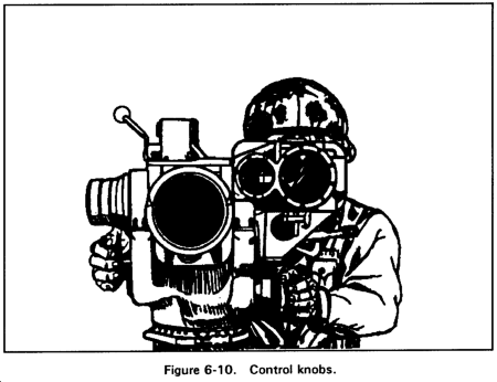
a. Position the eye well into the rubber eyepiece and place both hands firmly on the control knobs (Figure 6-10). P1ace the body so there is no contact between the shoulder and the encased missile. The only contact with the launcher is with the hands and eye. Assume a firing position that is comfortable. An uncomfortable position causes muscle tension, which affects the ability to track smoothly.
NOTE: When firing from the tripod, kneel on one or both knees.
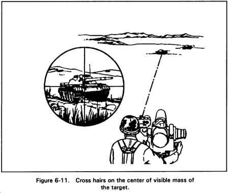
b. Raise the trigger protective cover and establish a smooth tracking rate while keeping the cross hairs on the center of visible mass of the target (Figure 6-11).
c. Move the launch tube left or right by applying a smooth, steady force to both control knobs (pushing one and pulling on the other) and rotating the body from the waist up as the launcher moves. Elevate or depress the launch tube by applying a smooth, steady turning force to both control knobs. Applying pressure to only one control knob, or applying uneven pressure, makes it more difficult to track smoothly. Maintain the same arm, shoulder, and head position throughout an engagement. Any change in body position other than leaning with the controls will cause a jerking motion that could result in grounding of the missile.
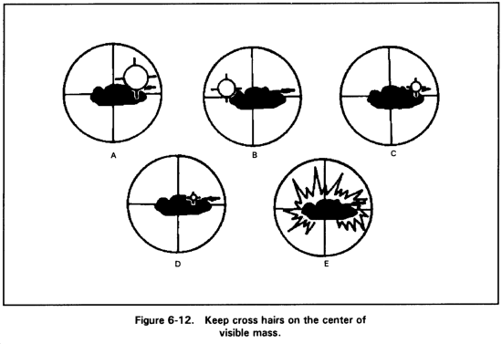
d. Proper breath control is especially important during the first and last 400 meters of missile flight. Improper breathing will cause poor tracking. Take a deep breath and let part of it out; then, press the trigger. After a 1.5-second delay, the missile will launch. The delayed firing of the launch motor may cause you to flinch or jerk the control knobs if you are not prepared for it. Be prepared for two noises after the trigger is pressed. The first noise is the gyro being activated. While it is not loud, it may cause you to think a misfire has occurred, and you may not be prepared for the next noise. The second noise is the launch motor firing and it is loud. The dust, smoke, heat, and debris from the backblast may cause flinching. When the missile appears in the sight picture, ignore it. Never try to guide the missile. If distracted, tracking becomes poor and chances of hitting the target are reduced. Continue to track the target at a smooth tracking rate, keeping the cross hairs on the center of visible mass until missile impact (Figure 6-12).
6-5. TARGET ENGAGEMENT WITH THE M220A2 (TOW 2)
Specific procedures are followed to engage a target using the M220A2.
a. Looking through the daysight tracker, adjust the focus control until the cross hairs are in focus. (To see the cross hairs clearly, set RETICLE LIGHT switch to ON.) Position the cross hairs on the target, and remove the front lens cover from the nightsight by releasing two latches. Set the ON-OFF-STBY switch to ON. Look through the eyepiece and adjust the diopter adjustment ring to focus the reticle. Ensure the battery monitor light is off. Set the field of view selector to wide field of view, locate the target, and adjust the range focus, contrast, and brightness controls to obtain the best possible sight picture. Set the field of view selector to narrow field of view and adjust the range focus, contrast, and brightness knobs.
(1) Because handoff may occur when limited visibility conditions exist, locate the target with the daysight tracker and fire using the nightsight. During daylight, the battlefield can be obscured by smoke, dust, and so forth. If limited visibility conditions exist, the MGS automatically transfers control of the missile from the daysight tracker to the nightsight. The nightsight allows continuous observation of the target regardless of battlefield visibility conditions.
(2) To view the battlefield, ensure the TOW 2 nightsight ON-OFF-STBY switch is in the ON position. Battlefield conditions requiring the nightsight to be in operation are area target monitoring and target engagement. The ON-OFF-STBY switch on the TOW 2 nightsight allows greater battery life from the BPC when placed in the STBY position. After the TOW 2 nightsight has been turned on and allowed to cool down (about three minutes), place the ON-OFF-STBY switch in the STBY position. The STBY position causes the closed-cycle cooler to cycle OFF for 100 seconds and ON for 20 seconds. Cooldown is not required if the nightsight has been operating in the STBY position.
(3) When firing the TOW 2 system, ensure the nightsight is turned ON. Always allow three to five minutes cooldown time before operation regardless of which sight is used. This ensures that the enhanced capabilities of TOW 2 are used during firing, flight, and impact. Certain conditions may permit degraded firing. During the system check-out procedure, if the display indicates a nightsight (postamplifier) failure, the TOW 2 can be fired using the daysight tracker only. If limited visibility causes handoff during flight, control of the missile may be lost.
b. To complete the firing sequence, follow the procedures for the basic TOW launcher (paragraph 6-4).
Section II. HELICOPTER ENGAGEMENT
Enemy armor is the primary threat to friendly ground forces employed in forward areas. The primary mission of the TOW is the destruction of these tanks at the greatest possible range. However, TOW gunners can also successfully engage attacking enemy helicopters, which are a significant threat to ground forces.
6-6. OPERATIONAL CONCEPT
Engaging helicopters with TOWs should be considered primarily as a means of self-defense. TOW crews should not consider helicopters as a routine target of opportunity, but they should leave them to conventional ADA assets when possible.
a. TOW positions are selected to cover armor avenues of approach, but these long-range fields of fire also facilitate the engagement of aircraft. The section leader's, squad leader' s, and crew's observation from these positions can provide the early warning required to successfully engage aircraft.
b. The engagement of attacking helicopters should be done by TOW sections, not individual weapon systems. TOW sections should automatically engage helicopters that are attacking their positions. If one squad in a section is being attacked by a helicopter, the other squad should engage the helicopter while the first squad seeks cover. TOW crews and sections should be trained to automatically respond to helicopter attacks in this manner.
6-7. GUNNERY TRAINING
Specific gunnery training is required to track a helicopter with a TOW. Crews should perform the training according to the following conditions and standards. In addition to these outdoor training exercises, a number of scenarios for the TGT include helicopters as targets.
a. Conditions. Training takes place during daylight on a range. The TOW crew is given either a ground-or vehicle-mounted TOW with a TFTT and a helicopter mounted with TFTT reflectors. The helicopter moves toward the TOW gunner at speeds between 40 and 80 knots and at ranges between 1,000 and 3,500 meters. Three target angles are used for tracking: head-on; approaching at 30 degrees; and an evasive track with a 90-degree turn.
b. Standards. Within 5 seconds the gunner must acquire and begin tracking the target. He must get a hit 6 out of 10 times with the TFTT.
Section III. NBC AND LIMITED VISIBILITY CONDITIONS
Specific procedures are followed to operate the TOW during NBC and limited visibility conditions.
6-8. DECONTAMINATION
TOW crewmen must know decontamination procedures and materials. They must know which decontamination materials to use on each type of surface on the weapon system. Using the wrong material can cause damage to the system (for example, using DS2 on rubber surfaces). Decontamination materials and methods are periodically revised. (Refer to Appendix C of FM 3-5 for the most up-to-date information.)
6-9. THERMAL TARGET RECOGNITION, IDENTIFICATION, AND ENGAGEMENT
The nightsight allows the TOW gunner to view targets during limited visibility conditions such as darkness, smoke, fog, rain, and snow. It produces images called thermal target signatures or infrared target signatures, which are different from the images seen in the daysight tracker. Targets standout in these infrared images and can be recognized at long ranges on a clear night and at reduced ranges during poor visibility. Recognizing these targets requires trained and experienced gunners.
a. Temperature and Thermal Images. Most objects have a radiated temperature either higher or lower than their background. Even if the radiated temperature differences are less than a degree, they appear on the nightsight display. If there is no difference between the temperature of an object and its background, the object will not be seen in the display.
(1) If an object has a high temperature, it will appear bright red in the nightsight. If the object has a low temperature, it will appear black. Usually, targets are easier to identify at night, because their radiated temperature is hotter than their background.
(2) Some targets, such as tanks and APCs, have internal temperature variations that form visible patterns. These patterns are the basis of target signature cues. In a nightsight, the shapes of the hottest vehicle parts, such as engines and exhausts, appear bright red. Objects with a medium temperature, such as the warm tracks, appear a dim red. Objects with a cool temperature, such as the cool hull and other cool parts, appear black.
b. Sources of Infrared Energy. Infrared energy comes from different sources such as solar heat, fuel combustion heat, frictional heat, and reflected radiance.
(1) Solar heat. Solar heat comes from the sun and affects the exterior surface of objects. This heating highlights the outline of the object, which provides recognition cues to the gunner. These cues are usually similar to the overall appearance of the target. (For example, a solar-heated M113 appears box-like with a sloping front; a solar-heated M60 tank appears as a small oval atop a larger oval.) These shape cues are recognizable out to medium (1,000 to 2,500 meters) and long (beyond 2,500 meters) ranges. Since the sides have more defined contours, the side view shapes are usually easier to recognize than the front view. In addition to atmospheric variables and surface reflections, the solar heating rate is also affected by the object's ability to absorb sunlight. Generally, dark-colored objects are better absorbers of sunlight than light-colored objects.
(2) Fuel combustion heat. Fuel combustion heat comes from operating engines. The heat from operating engines is conducted to the surfaces of the surrounding engine compartment.
(a) Because engine compartment temperatures reach up to 200F, the surfaces of these compartments radiate features that can be easily detected on the nightsight at long ranges. Heated personnel space is also visible.
(b) Engine muffler and exhaust pipe temperatures are high, providing the gunner with good cues.
(c) Although the engine, heated compartments, and exhaust features themselves do not appear in the nightsight, their cue value is not any less. A trained and experienced gunner can determine much about the vehicle from these cues.
(3) Frictional heat. Frictional heat is produced by the moving parts of vehicles. However, these features usually appear a dim red. This heat is less intense than the high temperatures from the engine combustion. Frictional heat is generated only when the vehicle is in motion.
(a) Frictional heat provides long-range cues to classify the vehicle as wheeled or tracked. At medium-range to short-range, these cues can be used to identify the vehicle.
(b) The vehicle's transport systems are the source of most frictional heat cues. Tracked vehicles have frictional heat in the tracks, road wheels, drive sprockets, support rollers, and shock absorbers. The smallest of these features can be identified at longer ranges when they are hot. Wheeled vehicles have frictional heat in the tires, shock absorbers, drive shafts, transmissions, axles, and differentials. The tires, shock absorbers, and differentials can be detected at medium-range to long-range.
(4) Reflected radiance. Certain smooth, glossy surfaces, such as windshields and glossy painted fenders, reflect radiation images from other sources. These reflections can produce odd images. For example, the fenders of a T-62 appear black because of thermal reflection; a glossy painted APC could be reflected off the vehicle's flat side surfaces. An overcast sky can cause warmer thermal reflections. Generally, surface reflections are diffuse in nature and do not usually cause problems.
6-10. EFFECTS OF WEATHER AND OBSCURANTS
Variations in solar heat, fuel combustion heat, frictional heat, and thermal reflection affect infrared signatures and infrared target recognition cues. In addition, some atmospheric conditions degrade the nightsight, while others can enhance it. Some of these factors are discussed below.
a. Falling Precipitation. Infrared energy does not transmit well through falling precipitation (rain, snow, and fog). The temperature of targets and background objects are decreased. The basic signature cues themselves do not change because of atmospheric transmission losses. Falling precipitation restricts nightsight visibility more than precipitation that has fallen.
(1) During rain or snow, background objects and frictionally heated and solar-heated target features lose heat. Frictional heat loss is caused by water and mud accumulating on the tracks, wheels, and other transport system parts. Engine compartment and exhaust temperatures remain high. Landmarks, such as tree lines, trails, and contour features, are often lost. The loss of heat in background objects reduces scene clutter, such as trees and rocks, and can increase target detection. Target recognition cues are usually reduced because of the loss of heat in certain target features.
(2) Because rain and snow have a cooling effect on the target's contrast, the nightsight contrast controls must be increased to compensate for the condition. However, a higher contrast setting produces a "snowy" image.
b. Fallen Snow. Fallen snow tends to make all ground temperatures the same. Depth perception by size comparison becomes difficult because of lack of terrain features with which to reference size.
c. Dust, Diesel Fog, and Oil Smoke. Dust particles from artillery impact greatly reduce nightsight visibility. Only the hotter objects and target features show through the obscurants.
6-11. COMPENSATION FOR TARGET APPEARANCE VARIABLES
Although vehicles have distinguishing characteristics or cues by which they can be classified and identified, vehicle appearance can be altered by changes in atmospheric and ground conditions. Therefore, the gunner must know to use the control settings of the nightsight to help compensate for these variables.
a. Contrast and Brightness Control. The contrast and brightness controls can be set for maximum internal detail of the target. The controls are balanced to give the clearest image of these target recognition cues. The following is general guidance for setting the image brightness and contrast controls. Gunners should be encouraged to experiment with the controls to understand the effects of the image controls on the thermal image and thermal signatures.
(1) Brightness, Low; Contrast, Medium to High: These settings are for scanning an area in search of targets. Background clutter is suppressed. Cool objects are not visible. Only the hot objects in the field of view are seen. When a possible target has been found, brightness can be increased and contrast can be lowered gradually to reveal more thermal detail in the suspected target. Low brightness and medium-to-high contrast settings are also for nightsight use in light fog, rain, or dust conditions.
(2) Brightness, Low to Medium; Contrast, Medium: This is the best overall setting for target detail. With medium contrast, brightness can be varied up and down to bring out features and determine the hottest vehicle parts. When brightness is lowered, the cooler parts, such as tracks, darken before hotter parts. Often, small changes in brightness can reveal much about the vehicle. For example, road wheels can sometimes be seen at long range if this technique is used. Experimentation is helpful in learning this target feature extraction technique.
(3) Brightness, Medium; Contrast, Medium to High: These settings work well in heavy fog or heavy dust when little can be seen with the TOW. The settings increase the snowy effect in the image, but they also increase the apparent sensitivity of the sight. The image appears distorted and is difficult to interpret. These settings are also good for searching a tree line in wet conditions. They are sometimes useful with long-range targets. Beyond 2,500 meters, small target images, such as the front view of a BRDM-2, will have a few recognizable features. At long ranges, the higher contrast setting highlights the vehicle's hull and overall silhouette. This will not provide internal detail, but it will help the target stand out from the background and will aid in target detection.
b. Focus Controls. Most nightsight focus controls are sensitive; that is, a small movement of the control knob results in a large change in focal point. If a gunner has difficulty in focusing, he should check the adjustment of the image controls.
(1) The eyepiece focus should be adjusted first. The eyepiece focus is called the diopter adjustment. Once a gunner knows his diopter correction number, he can dial it in on any nightsight diopter ring. Correct diopter adjustment can usually be obtained by focusing the eyepiece so that the reticle is focused.
(2) The second focus adjustment is the objective range focus. The image controls should be adjusted at the low-to-medium level before focusing the objective lens. Focusing the objective lens is learned through trial and error. It is made difficult by the fact that infrared heat diffuses on objects and does not usually give clear-cut, straight lines on which to focus. Thus, the gunner must learn to focus by adjusting the control back and forth to get the best image. This is easier to do when the nightsight is aimed at a prominent object. Once the best image is determined, the gunner can experiment by focusing on different objects at different ranges.
6-12. BATTLEFIELD IDENTIFICATION
Battlefield identification using a nightsight is difficult. Although the identification problem is being studied, little is known about the ranges at which high-confidence identification can be expected. In a target-rich environment on a dry, clear night, high-confidence identification requires a thermal image of such features as road wheels, turret shapes, gun tube, and exhaust location. Limited experience indicates that the M60 versus T-62 thermal identification can be made between 1,000 to 2,000 meters in clear weather. When identifying targets, a gunner should ask himself these questions:
- Is the target moving?
- What direction is it moving?
- Where is the engine?
- Where is the exhaust?
- Is the target in the unit's sector?
- Should it be there?
- Is it in a formation?
- Is it firing at the unit?
6-13. PRIMARY RECOGNITION CUES
The following friendly and enemy vehicle recognition cues aid in training gunners.
a. M1 ABRAMS Main Battle Tank.
(1) Classification.
(a) Rear-engine vehicle.
(b) Oval-shaped track and road wheel pattern.
(c) Gun tube visible when recently fired.
(2) Identification.
(a) Side-view cues:
- Rear-engine vehicle with rearward exhaust.
- High-profile track pattern with hot, taut tracks (seven road wheels with wider gap between first and second wheel and three support rollers).
- Needle-nosed turret with flat angular sides, centered on chassis.
- Long gun tube is visible at long ranges when recently fired. (Bore evacuator is two-thirds of the way down the length of the barrel.)
- Left and right views are the same.
(b) Front-view cues:
- Two warm tracks separated by cool hull.
- Cool front hull denotes a rear-engine vehicle.
- Gun tube is visible when the gun has been recently fired.
(3) Effects of motion.
(a) Changing target views often reveal more features.
(b) Direction of movement denotes engine location.
(c) Bouncing is slower than that of a light vehicle.
(d) Exhaust plume location and direction are sometimes visible.
b. T-62 Tank.
(1) Classification.
(a) Rear-engine vehicle.
(b) Oval-shaped track and road wheel pattern.
(c) Overall combined hull, turret, and gun pattern may be visible with maximum setting.
(d) Gun tube is visible when it has been recently fired.
(2) Identification.
(a) Side-view cues:
- Rear-engine vehicle with left side exhaust.
- Low-profile slack tracks (five road wheels with unique spacing visible at short ranges).
- Left side hotter than right side.
- From left side, the rear half of the vehicle has a much larger heated area than the front half.
- Low overall profile with cool hull.
- Long gun tube (is visible when it has been recently fired).
- Small centrally mounted turret.
(b) Front-view cues:
- Cool, low overall profile with warm tracks separated by cool hull.
- Cool fenders above tracks may appear black.
- Small, dome-shaped turret.
- Long gun tube is visible when it has been recently fired. It appears as a red spot when aimed toward the unit. When unfired, it is visible only at short ranges.
(3) Effects of motion.
(a) Changing target views often reveal more features.
(b) Direction of movement denotes engine location.
(c) Transport system becomes warmer and more visible.
(d) Bouncing is slower than that of a light vehicle.
(e) Exhaust plume location and upward direction are sometimes visible.
c. M2/M3 Bradley Fighting Vehicle.
(1) Classification.
(a) Front-engine vehicle.
(b) Oval-shaped track and road wheel pattern.
(c) 25-mm barrel visible when recently fired.
(d) Amphibious.
(2) Identification.
(a) Side-view cues:
- Front-engine vehicle with upward exhaust.
- Has reinforced body armor where the shroud and body connect.
- High-profile track pattern with hot, taut tracks (six road wheels with gap between third and fourth road wheel and three support rollers).
- High overall center-mounted turret with TOW launcher on left side, centered on chassis.
- 25-mm gun barrel is visible at long range when recently fired.
- Left and right views are the same.
(b) Front-view cues:
- Two warm tracks separated by hot hull.
- Hot front hull denotes a front-engine vehicle.
- Gun barrel is visible when the gun has been recently fired.
(3) Effects of motion.
(a) Changing target views often reveal more features.
(b) Direction of movement denotes engine location.
(c) Bouncing is faster than that of a heavier vehicle.
(d) Exhaust plume location and direction are sometimes visible.
h. BRDM-2 Reconnaissance Vehicle.
(1) Classification.
(a) Rear-engine vehicle and exhaust
(b) Wheel pattern of separate wheel-size red spots.
(c) Overall profile of hull with (or without) turret.
(d) Gun tube is visible when it has been recently fired.
(2) Identification.
(a) Side-view cues:
- Rear engine is clearly visible at long ranges.
- Two tires clearly visible (each side). Their separation distance suggests a short wheel base vehicle.
- Two mufflers--one on each side of the top rear deck--increase engine area hot spot.
- Overall small size of vehicle is apparent.
- Side view gives a characteristic heat pattern formed by the rear mufflers and the wheels. This pattern is distinctive even at long ranges.
- Choppy ride over rough terrain is quite noticeable even at long ranges.
- Left and right views are the same.
(b) Front-view cues:
- Two warm tires separated by a cool hull. Red spot of differential may be visible between front tires.
- The cool front hull denotes a rear-engine vehicle.
NOTE: Entire frontal area may be made to appear hot if control is set on high.
- Dark surfboard is visible across the front of the hull.
- Tires are set closer together than tracks of most armored vehicles.
- The frontal aspect of the vehicle appears to have a higher "height to width" ratio than armored vehicles which appear wider and lower.
- Over rough terrain, the vehicle tends to bounce more than armored vehicles.
(3) Effects of motion.
(a) Changing target views often reveal more features.
(b) Direction of movement denotes engine location.
(c) Transport system becomes warmer and more visible.
(d) Exhaust plume location and upward direction are sometimes visible.
(e) This vehicle is lighter and shorter than tracked, armored vehicles and, therefore, will bounce more and generally will exhibit a choppier ride over rough terrain.
(4) Special notes.
(a) The first two front-view cues of this vehicle indicate that it is wheeled and has a rear engine. This information leads the observer to eliminate most trucks and most heavily armored vehicles as target possibilities.
(b) The side pattern is distinctive and easily recognized. The front pattern is more difficult. The front oblique pattern is difficult and can be confusing and misleading.
(c) Top-mounted weapons and electronic accessories can change the upper vehicle signature considerably, but the basic cue pattern of hull, wheels, and engine or muffler features should persist regardless of an y top side modification. However, the overall silhouette profile cues may be altered by such modifications.
SECTION IV. ELECTRO-OPTICAL COUNTERMEASURES
TOW crews may encounter electro-optical countermeasures on the battlefield. Therefore, the following procedures should be used as engagement criteria and not as maintenance checks.
6-14. TOW LAUNCHER
TOW gunners should complete boresight procedures at least as often as prescribed in the operator's manual to ensure the system remains boresighted. When properly boresighted, the boresight meter needles are centered. The sight sensor must point at the ground or away from the sun or any other possible source of IR energy when the boresight procedure is being completed.
a. Once the boresight procedure is completed, the TOW crew leaves the self-test selector switch in position 7 and engages the test/operate switch (move to test position and hold) as the gunner acquires the target. The missile arming lever should not be raised at this time. If the self-test meter needles peg to one side, or become erratic, or both as the gunner aims at the target, electro-optical countermeasures are present and a shot against that target should not be attempted. The gunner waits for a flank shot or shifts targets.
b. The loader releases the test/operate switch as the gunner shifts targets. The loader reengages the test/operate switch (returns it to test position) when the gunner is ready to acquire a second target. Releasing the switch saves wear and tear on the daysight tracker sensor and conserves battery power, if batteries are being used.
c. If the meter needles return to center after the gunner places his cross hairs on a second target, he engages the target. The loader releases the test/operate switch and raises the arming lever, and the gunner fires the missile.
d. If the meter's needles are erratic after the gunner lays on the second target, he does not fire. He selects another target or waits for an oblique or flank shot ensuring the meter needles are centered before firing.
6-15. TOW 2 LAUNCHER
TOW 2 launchers firing TOW 2-series missiles are not vulnerable to electro-optical countermeasures. However, TOW 2 launchers firing non-TOW 2 missiles are vulnerable, and gunners should use the boresight indicators to determine whether a target should be engaged.
a. The loader completes the MGS self-test procedure as target engagement becomes imminent. The loader holds the self-test toggle switch in the test position before the missile is armed, as the gunner places his cross hairs on the target. If the green light stays on indicating electro-optical countermeasures are not present, the loader releases the toggle switch and raises the arming lever, and the gunner engages the target.
b. If the green boresight center light goes off and the red lights begin to flicker on and off indicating electro-optical countermeasures are present, the gunner does not engage the target. The loader holds the self-test toggle switch in the test position as the gunner acquires an alternate target. If the red lights go off and the green light comes on as the gunner lays his cross hairs on a second target, the loader releases the self-test toggle switch and arms the missile, and the gunner engages the target.
c. Because the TOW 2 self-test switch is reactivated each time the toggle switch is placed in the test position and the self-test cycle takes 15 to 20 seconds, the loader does not release the test switch while the gunner is acquiring alternate targets. The leader releases the switch only after the green boresight light appears, signifying that it is safe to engage that target.
|
NEWSLETTER
|
| Join the GlobalSecurity.org mailing list |
|
|
|