

APPENDIX E
STANDARD RANGE CARD
This appendix describes the various parts of a standard range card. It also provides a detailed discussion of how to complete a range card.
E-l. DESCRIPTION
A range card is a sketch of the terrain a weapon system has been assigned to cover by fire. It contains information that assists in the planning and controlling of fires, the rapid detection and engagement of targets, and the orientation of replacement personnel or units. By using a range card, a gunner can quickly and accurately determine the information he needs to engage targets.
a. A sector of fire is a part of the battlefield within which a gunner is responsible for engaging targets. Sectors of fire are assigned to ensure weapon systems will cover target approaches. Leaders should strive to overlap sectors to cover areas that cannot be engaged by one system. The leader gives a gunner boundaries running between prominent terrain features, or by left and right limits indicated by terrain features or azimuths. If necessary, the leader also assigns a gunner more than one sector of fire, designating one sector as primary and others as secondary.
b. The section/squad leader may also designate anticipated target engagement locations within the sector of fire. Those are recognizable terrain features on or near likely enemy avenues of approach. This information is placed on the range card.
c. Leaders may pick out natural or man-made terrain features that can be used as reference points for locating targets and adjusting direct/indirect fires. Those features are called target reference points (TRPs). TRPs are requested through the mortar or artillery fire support team (FIST) or fire support officer (FSO). If TRPs are in or near the sector of fire, the leader should point them out and tell the gunner their numbers. If he does, the gunner depicts the TRPs on his range card. Normally, a gunner has at least one TRP, but not more than three, in his sector of fire.
d. Natural or man-made terrain features, such as hills, draws, or buildings, may be within the sector(s) of fire that prevent the gunner from firing in that area. The area blocked by these features is called dead space. All dead space in the sector(s) of fire must be determined so leaders can plan other weapon systems or other types of fire to cover the area (for example, mortars, artillery, or mines). Dead space is indicated on the range card.
e. The length of the sector of fire is normally limited by the maximum engagement range of the antiarmor weapon, but it can be less if any natural or man-made terrain features (trees, fences) prevent the gunner from engaging targets at maximum range. Regardless of what affects it, the maximum engagement range is shown on the card as a maximum engagement line. The squad leader uses a map to determine the distance to the maximum engagement line.
f. All TRPs, anticipated target engagement areas, azimuth and distance to a known point, and left and right limits are numbered on the sector sketch and in the data section with corresponding numbers for quick reference.
E-2. PREPARATION PROCEDURES
EXAMPLE OF SECTION/SQUAD LEADER'S BRIEFING
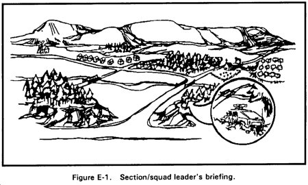
"Our mission is to cover a sector of fire that begins at our present position and goes in the direction of the windmill to the maximum engagement range of 3,750 meters; it extends to the right across the high ground behind the houses, and hill, to the right edge of the orchard and returns here. The enemy should approach from the north and will probably use both Marshall Road and Lewis Road to enter our sector. We must plan on engaging the enemy in this area as soon as he is within range. There are two target reference points within your sector; the road intersection of Marshall Road and Duffell Road is TRP-Charlie One and the road junction of Lewis Road and Duffell Road is TRP-Charlie Two. Use the road junction of Campbell Road and Lewis Road to your left as a reference point to locate your position. The distance from the road j unction is 633 meters on an azimuth of 85 degrees." (See Figure E-1.)
After the leader has given the necessary information, the gunner begins preparing DA Form 5517-R (Standard Range Card). If he is assigned alternate and supplementary firing positions, he prepares a range card for them also. The gunner prepares the range card by performing the following steps.
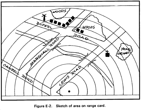
a. Draw a sector sketch of the entire sector. Make the sketch as large as possible, not to exceed the largest circle. For a large area covered by trees or woods, draw only the outline and lable the area; for example, "woods," or "orchard" (Figure E-2).
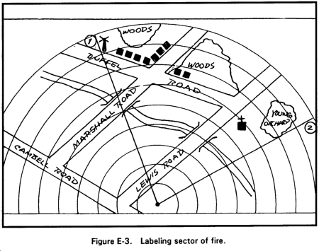
b. Draw lines from the weapon position (indicated by the black dot at lower center of range card) to show the right and left limits. Place a number 1 at the end of the left limit line and draw a circle around the number. Place a number 2 at the end of the right limit line and draw a circle around the number (Figure E-3).
NOTE: After drawing left and right limit lines, the weapon symbol can be drawn over the black dot.
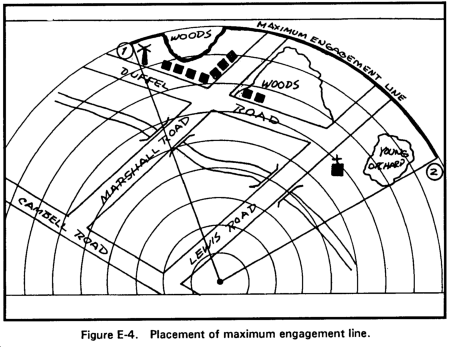
c. If there are no limitations, the maximum engagement line is curved and joins the left and right sector of fire boundaries at the maximum engagement range (Figure E-4). If there are limitations, the maximum engagement line is drawn in front of the limiting terrain feature.
d. Number the anticipated target engagement areas (ATEAs) from left to right, starting with number 3. Place a number at the maximum engagement range of the target on the range card and circle the number (Figure E-5).

e. Number the TRPs from left to right. Place the number below or next to the TRP on the range card and circle the number (Figure E-6).

f. Place diagonal lines, or the words "dead space," where dead space occurs (Figure E-7).

g. Use a compass to determine the azimuth from the firing position to the known point. Convert the direction to a back azimuth. Draw a line with multiple arrows from the known point to the firing position. Place a number at the known point and circle the number (Figure E-8).

h. Fill in the marginal information at the top of the card.
(1) Unit description--SQD, PLT, CO. Never indicate a unit higher than company level.
(2) Magnetic north. Orient the range card with the terrain. Place the compass on the range card. Determine the direction of magnetic north arrow and mark it on the card.
i. Fill in the data section at the bottom of the card.
(1) Position identification. List either primary, alternate, or supplementary.
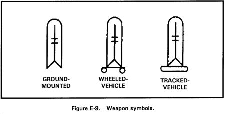
(2) Weapon. See Figure E-9 for weapon symbols.
(3) Date. List the day and month.
(4) Each circle equals _____ meters. Write the distance between the circles in meters. To determine the distance, count the intervals from the weapon to the maximum engagement line (as determined by the squad leader). Divide the amount of intervals into the range of the maximum engagement line. This will give the distance between circles (Figure E-10).
Example: 9 intervals into 3,750 meters = 416 meters between circles.

(5) No. (number). Starting with number 1, list the left limit, the right limit, and locations of ATEAs and TRPs shown on the sector.
(6) Direction/deflection. Only degrees or the azimuth from the azimuth bevel ring (improved TOW vehicle) is listed. Line through the word that does not describe the information listed.
(7) Elevation. This is only used with a ground-mounted machine gun using the traverse and elevation mechanism.
(8) Range. Distance in meters from the weapon to the TRP or target engagement area.
(9) Ammunition. List the type of ammunition used, if applicable.
(10) Description. List the name of the object; for example, road, windmill, church. If the item is a TRP, also list the TRP number.
(11) Remarks. Enter the weapon's reference point and any additional information not listed in the range card section. If more space in the data section is needed, use the reverse side of the range card.
j. Make two range cards. Keep one at the firing position and give one to the squad or section leader for preparation of fire plans and final coordination of fires. (See Figure E-11 for a completed TOW range card.)

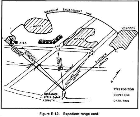
E-3. EXPEDIENT RANGE CARD
In combat, a DA Form 5517-R may not be available. The gunner must then draw a range card on anything available (Figure E-12). Preparation of the expedient range card follows the same procedures provided for the standard range card, but the weapon symbol must be used to indicate the location of the weapon position. The range card must include the following eight items:
- Weapon symbol.
- Sector of fire.
- Maximum engagement line.
- Range and azimuth to TRP/ATEA.
- Dead space.
- Distance and azimuth from a known point.
- Magnetic north arrow.
- Data section.
E-4. PREPARATION OF AN ITV FIRING POSITION FOR USE AT NIGHT
After an ITV crew makes a range card, they mark the position of the ITV. After dark, the same ITV or an ITV from another unit can move into the same position and use the prepared range card.
a. Flat Terrain to the Front.
(1) When flat terrain is to the front (Figure E-13)--
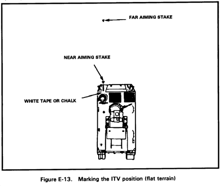
(a) Complete the range card.
(b) Put out two aiming stakes with red-filtered flashlights pointed toward the ITV. Center the closest aiming stake on the driver's position, touching the hull and high enough for the driver to see.
NOTE: At this time, the hull should be marked with tape or chalk where the stake touches the hull for later use.
(c) Place the other stake 20 to 25 meters in front of the ITV in line with the first stake as seen by the driver.
(d) The gunner places the cross hair of his sight on the far aiming stake and records in the remarks section of the range card the deflection determined by the pointer on the degree scale.
(2) To move into a marked position that has flat terrain to the front--
(a) Turn on the flashlights on the aiming stakes.
(b) Line up the ITV with the two lighted stakes and move the ITV until the tape (or chalk marks) and both stakes are in line and the hull is touching the stake.
(c) Place the cross hair of the gunner's sight on the far stake. The deflection reading for the far stake should be the same as the one written on the range card. If it is not, the driver can reposition the vehicle slightly by using pivot steer.
(3) The ITV is now ready to fire from the range card.
b. Sloping Terrain to the Front.
(1) When the terrain to the front of the ITV falls away sharply (such as a cliff or high hill) (Figure E-14)--
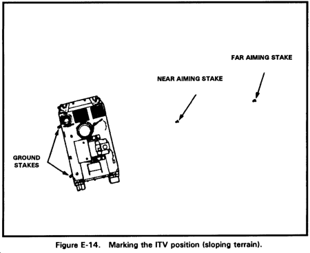
(a) Complete the range card.
(b) Put in two ground stakes on either the right or left side of the ITV, front and rear, at the outside edge of the track where it leaves the ground.
(c) Put the first (far) aiming stake 30 to 50 meters from the ITV at a deflection more than 6 degrees from the direct front or rear of the ITV (any deflection reading from 006 degrees to 174 degrees, and from 186 degrees to 345 degrees).
(d) Traverse the turret to lineup the cross hair of the gunner's sight with the far aiming stake.
(e) Put out the second (near) aiming stake halfway between the ITV and the far stake and on line with them.
(f) Record, on the range card, the deflection determined by the pointer on the degree scale.
(2) To move into a marked position that has sloping terrain to the front--
(a) Stretch white tape between the two ground stakes to help position the ITV track.
(b) Move the turret to the deflection reading from the range card.
(c) Move the ITV up next to the white tape.
(d) Stop the ITV when the gunner sees the far aiming stake in line with the near aiming stake. (This may require the gunner to talk the driver into the position.)
(e) The ITV is now ready to fire from the range card.
|
NEWSLETTER
|
| Join the GlobalSecurity.org mailing list |
|
|
|