Chapter 5
Network Database Management
This chapter describes database development and provides doctrinal guidance to accomplish those tasks. The discussion includes developing and managing an MSE database using the NPT. The NPT and the SCC-2 are used as the network status controller including the NMC for the TPN operation and management.
MANAGEMENT CONTROL |
|
5-1. The NPT, SCC-2, NCS, LENS, and their NMFs operate from a standardized network database. The critical part of long-range planning is initially generating the network database. The corps or the division G6, if establishing a stand-alone division network, sets up network management and control parameters for this process. 5-2. The signal brigade headquarters conducts management and control in an MSE corps network. The division signal battalion headquarters conducts management and control in a stand-alone division MSE network. Within these headquarters, the SYSCON conducts MSE network planning and operation. SYSCON maintains TECHCON of the network and is responsible for-
|
|
DATABASE DEVELOPMENT |
|
5-3. For signal planners, the supported unit's mission and planning guidance determine the content of the database. Signal planners may prepare one master database from which all missions evolve or prepare individual mission databases to support specific contingencies. The number of databases depends on the differences in force structure, missions, and geographical AO. 5-4. In operation plans (OPLANs), the force commander and staff define each mission, contingency, and exercise. The force signal staff prepares the databases and obtains the following information:
5-5. This information is then used to respond to one or more of the following areas.
5-6. The MSE database includes the global database (GDB), and it-
5-7. The GDB identifies joint (Commander-in-Chief (CINC)) level, US Army, US Air Force, US Navy, and US Marine organizations. The GDB manager (GDB MGR) is located with the US Army Signal Center. The GDB includes-
5-8. The NPT can develop the MSE network database, plan and engineer the network, and distribute team information to all appropriate switches. The SCC-2 acts as network status controller, and the NMC within the SCC-2 manages the operation of the TPN after it is initialized and loaded with the database. |
|
DIGITIZED MAP REQUIREMENTS |
|
5-9. The MSE NPT uses two types of map data for its software applications. Both are originally sourced from the National Imagery and Mapping Agency (NIMA) and are available on compact disk-read only memory (CD-ROM). 5-10. The ARC-Digitized Raster Graphics (ADRG) is a digitized picture of paper maps that clearly shows the terrain features (for example, rivers, roads, lakes, hills). They are available in five forms.
5-11. The digitized terrain elevation data (DTED), Level 1, provides the terrain data applied to the digitized map for use in site location and radio system profiling. |
|
HIGH POINT DATA REQUIREMENTS |
|
5-12. High points are developed using the high elevation retrieval option within the network planning-frequency assignment application of the NPT. A user-selected rectangular area, defined by coordinates of its southwest and northeast corners, can be established using appropriate map data. This rectangular area map plot can be divided into five rows of five columns (equaling 25 cells) with up to five high points per cell, so that selected high points may be chosen throughout the original map plot. When selecting high points, a minimum separation value is applied to prevent all high points from being on the same high piece of terrain (for example, single hilltop). With this capability, the NPT can make a map reconnaissance of potential site locations before making the physical reconnaissance. 5-13. Two other NPT software applications support high point refinement. The interactive asset placement (IAP) application searches for high elevation placement for particular radio links at a site that still profiles. The automatic asset placement (AAP) application checks for the centroid of mass of switches that an NC supports and identifies the highest ground within a 1-kilometer area of a selected site. 5-14. Signal planners must consider all METT-T factors when selecting potential high points. The final high point selection is coordinated with senior headquarters SYSCON and the G3. Other weapons and communication systems can have high points as key terrain. |
|
PREAFFILIATION LIST REQUIREMENTS |
|
5-15. The MSE database includes telephone numbers for fielded units contained on the switch PAL. This database contains a unique telephone number for each subscriber position. The database is updated annually according to actual subscriber requirements that allocate a specific type of terminal to each operational subscriber. 5-16. The PAL sublists identify subscribers' numbers and the associated profile service characteristics likely to be affiliated with the network. The signal organization planner, through the US Army Signal Center GDB MGR, manages the development of the PAL. A PAL database can have up to 1,000 PAL sublists (database designators DB000-DB999). Each PAL sublist can contain a maximum of 200 subscribers. Each sublist is developed according to the standard requirements code (SRC) assigned to each unit or entity within a PAL database. The sublist may include command structure or community of interest, such as division main (DMAIN), division tactical command post (DTAC), or division rear (DREAR). PAL sublists are a part of the global PAL (GLPAL) baseline that includes all joint and US military services. 5-17. The doctrinal guidelines for developing a PAL database are shown below. 5-18. Assign unit or telephone prefixes (first part of the phone number) according to the Global Block Numbering Plan (GBNP) approved in June 1995, and subsequently changed or defined by the GDB MGR. 5-19. Assign telephone numbers by using the prefix from the unitlist.dbf and associating a suffix from the suffix.dbf based on the SRC or subscriber template. The subscriber database is created from association and reviewed by the network manager or PAL manager of the specific PAL database. Units should use the subscriber database to develop telephone directories to meet their requirements. 5-20. Ensure a subscriber's telephone number is unique with a profile assigned and placed only on one sublist. 5-21. Develop PAL sublists along task organized lines, depending on requirements. A subscriber's DNVT and MSRT number may appear on different PAL sublists. This depends on the way the network deploys and supports the units. 5-22. Group GLPAL sublists for corps into DB000-DB999 signal technical numbers as shown in Table 5-1. 5-23. Group GLPAL sublists for all other databases into DB000-DB099 signal technical numbers as shown in Table 5-2. |
|
Table 5-1. Corps GLPAL Sublists
Database Designators |
Community of Interest |
| DB000 DB001-DB009 DB010-DB019 DB020-DB029 DB030-DB039 DB040-DB049 DB050-DB059 DB060-DB069 DB070-DB079 DB080-DB089 DB090-DB094 DB095-DB099 |
Area Brigade DBA00 Corps Signal Brigade SCC-2/ ISYSCON Area Battalion DBA01 Corps Area Battalion DBA02 Corps Area Battalion DBA03 Corps Area Battalion DBA04 Corps (Support) Division DBD01 Division DBD02 Division DBD03 Division DBD04 Division DBD05 Division DBD06 Division DBD07 |
Table 5-2. GLPAL Sublists for Other Databases
Database Designators |
Community of Interest |
DB000 |
Area Brigade DBA00 |
5-24. Table 5-3 shows an example of the switch PAL. |
Table 5-3. Switch PAL
| Switch PAL Example | ||
| PA520597 contains 9 PALs | ||
| PAL Number 52001 | ||
| I_CTSC 29 SC BN NCS 5201 | ||
| 9 entries: 5200101 5200102 5200103 5200104 5200105 5200106 5200110 5200111 |
184 190 190 190 190 190 190 190 190 |
|
5-25. Do not include data terminal adapter (DTA) numbers in switches on PAL sublists or subscriber databases. The network uses these numbers to communicate between switches. They follow the format of DB99907 (999 is number 000-099 and 07 is standard for all flood search switches). 5-26. Group all signal battalion MSRT numbers on one PAL. This allows the signal numbers needed for network control to activate in the first operational NCS and ensures that signal managers have immediate access to the evolving network. Other MSRT subscribers may use a similar rule, so they may have phone service as soon as they enter the area. 5-27. The NPT can accept a PAL load disk with its PBOOKII software application. Do not use PBOOKII software when modifying and updating a PAL. The PBOOKII software application provides an electronic phone book to support tactical switching. It also supports the 63 and 255 profile matrix standards with version 2.01 and the GDB with version 2.02. |
PROFILE LIST REQUIREMENTS |
|
5-28. Profiles provide particular phone service and system features to wire and mobile subscribers. The subscriber's profile defines the level of authorized service to each MSE subscriber. A method of developing profiles is to classify the subscribers by type and/or position. Each subscriber is assigned a permanent profile. This profile can be changed temporarily at the switch; however, this is the exception not the rule. Signal planners must consider area TMD communications support requirements, whereas TMD assets require dial-hold (channel reassignment function) circuits through the MSE network. 5-29. The US Army uses the GSPM 255 0895 matrix, which replaces the earlier Army Standard Profile Matrix 0191. The GSPM 255 0895 matrix-
5-30. Six basic groups within the matrix are
5-31. There are 50 subgroups which are categorized by profile and precedence order. The COMSEC rekey rule states that a maximum of 250 mobile subscribers should be assigned on a single rekey ID within a network. All wireline subscribers are assigned to one rekey ID-01. Fourteen mobile groups with unique rekey IDs will assist in preserving the COMSEC limit of 250. 5-32. The GSPM contains the old profile numbers cross-referenced to the GSPM profile. The US Army Signal Center initially converts all databases to the GSPM profiles. Each signal organization network manager may review each subscriber to determine if the new profile meets the subscriber's requirements. Each group for DSVTs converts to 03, 04, and 06, which translates to 009, 010, and 015, respectively. MSRTs may convert directly to MSRT groups 1-7 from old groups 1-7, or MSRT groups 1-7 for division slots and MSRT groups 8-14 for corps troops. EAC and other databases may only use MSRT groups 1-7. 5-33. Figure 5-1 shows the GSPM. The network manager must complete the profile matrix to initiate the MSE network. |
|
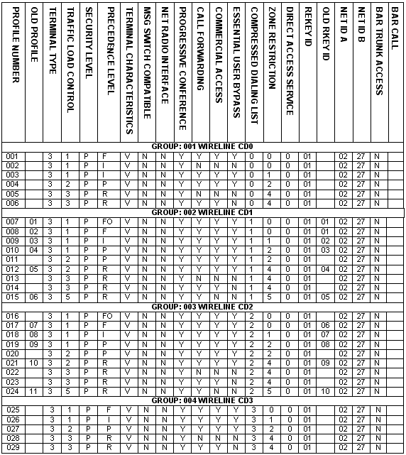
Figure 5-1. GSPM

Figure 5-1. GSPM (Continued)
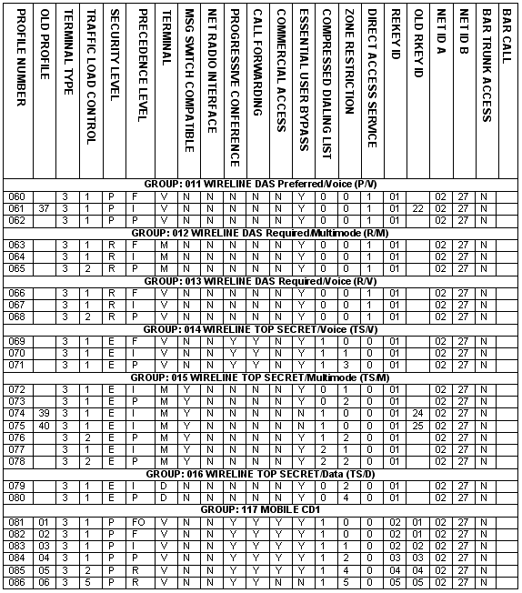
Figure 5-1. GSPM (Continued)
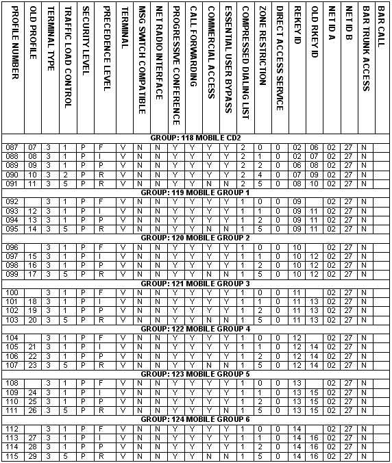
Figure 5-1. GSPM (Continued)
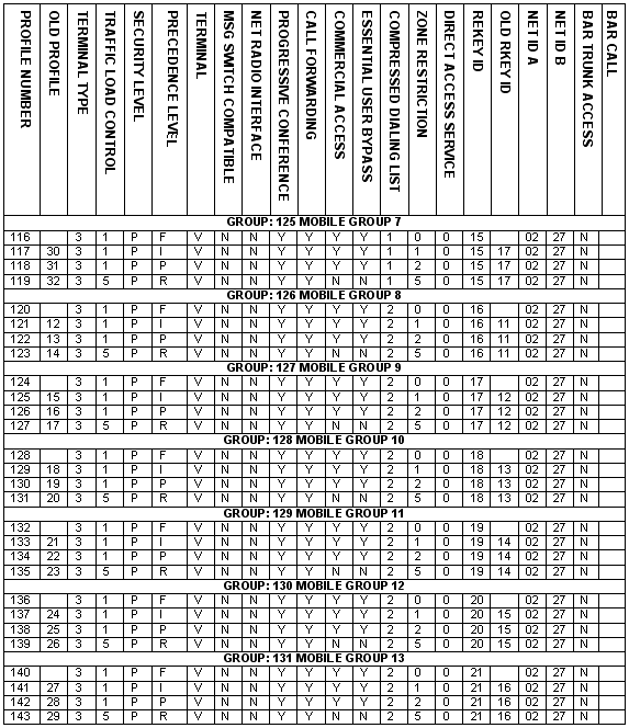
Figure 5-1. GSPM (Continued)
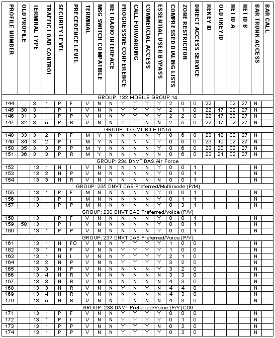
Figure 5-1. GSPM (Continued)
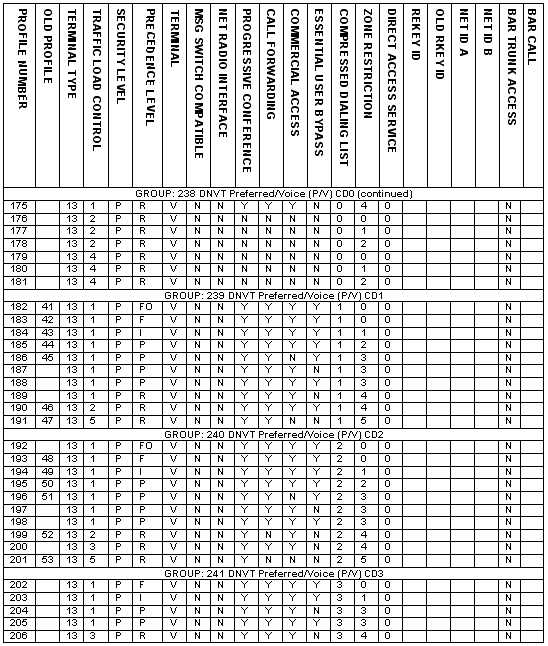
Figure 5-1. GSPM (Continued)
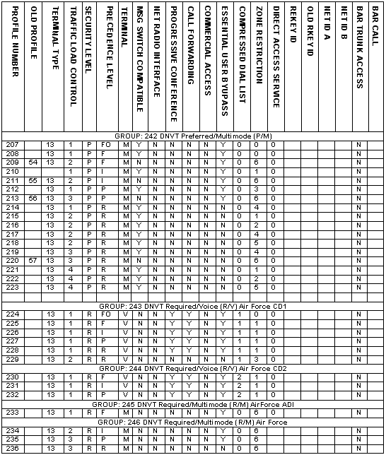
Figure 5-1. GSPM (Continued)
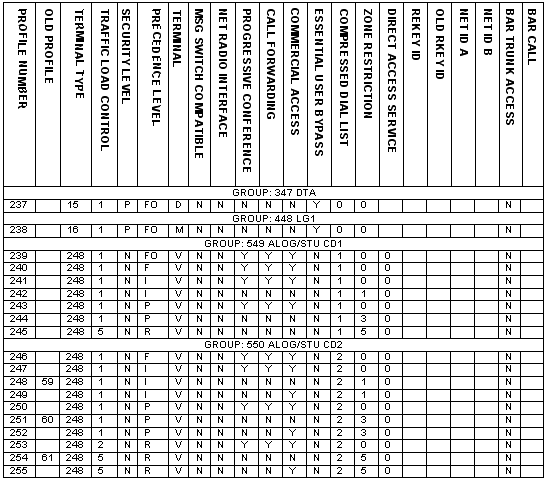
Figure 5-1. GSPM (Continued)
| 5-34. Profile 238 is used for the RAUs GLU and 237 is used for the DTAs. The other 253 profiles for subscriber equipment contain all five levels of precedence for operation and control purposes. Table 5-4 shows the percentage of precedence category calls a network will contain. |
Table 5-4. Percentage of Precedence Category Calls
Percentage |
Precedence |
0.0% |
Flash Override (FO) |
| Note: Source is Chairman, Joint Chiefs of Staff Memorandum (CJCSM) Publication 6231.07A series. |
| 5-35. Table 5-5 shows the class marks, which make up a subscriber's profile and the input codes associated with each class mark. |
Table 5-5. Class Mark Input Codes
CLASS MARK |
|
VALID INPUTS |
|
INPUT CODES |
Terminal Type |
|
DSVT |
3 |
|
Traffic Load Control |
Most Essential |
|
1 |
|
Security Level |
|
Security Required |
|
R |
Maximum |
|
Flash Override |
|
FO |
Terminal |
Voice |
|
V |
|
Message Switch |
|
Yes |
|
Y |
NRI |
|
Yes |
|
Y |
Progressive |
|
Yes |
|
Y |
Call Forwarding |
|
Yes |
|
Y |
Commercial Network |
|
Yes |
|
Y |
Essential User |
|
Yes |
|
Y |
Table 5-5. Class Mark Input Codes (Continued)
CLASS MARK |
|
VALID INPUTS |
|
INPUT CODES |
Compressed Dialing |
|
Not Authorized |
|
0 |
Zone Restriction |
|
No Restriction |
|
0 |
Direct Access |
|
Yes |
|
Y |
Rekey |
|
1 |
|
1 |
Net ID A |
|
2 |
|
2 |
Net ID B |
|
27 |
|
27 |
Bar Trunk Access |
|
Yes |
|
Y |
Bar Call |
|
Yes |
|
Y |
|
5-36. The different subscriber terminal types within MSE can include-
|
Note: DNVTs or MSRTs must connect to a switch and have an individual directory number. |
|
5-37. TLC reduces network traffic during busy periods by efficiently using available switching and transmission resources. TLC restricts trunk access and local calling to class marked subscribers. Subscribers should be class marked for one of the five TLC levels shown in Table 5-38. The switch's TLC restrictions rule how the subscriber's TLC class mark is used in the MSE system. Table 5-6 explains how the switch uses class marks. |
Table 5-6. TLC Application
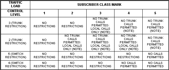
Note: A local- or long-loop subscriber or private branch exchange (PBX) trunk attempting a trunk call is returned a line-busy tone. The call is not completed. Time-out actions on sending a line-busy tone is IAW the specific requirements of the particular loop or trunk. (See individual signaling and supervision appendices for details.) A digital in-band trunk signaling (DIBTS) trunk attempting a call is returned a call incomplete (all trunks busy from tandem switch). |
5-38. The three security level class marks are security required (R), security preferred (P), and end-to-end (E). In profile development, only preferred and end-to-end are used. 5-39. Security required is used when a subscriber can only complete calls over secure links to approved loops or to a DSVT. 5-40. Security preferred are calls extended as secure, if possible; otherwise, the call is completed in a nonsecure mode. Most terminals are class marked as security preferred. Security preferred is for access to commercial networks and to the DISN. 5-41. End-to-end applies only to DSVTs. DSVT subscribers can only call other DSVT subscribers. 5-42. All five precedence levels can be assigned. The maximum precedence entry specifies the highest precedence level a subscriber may impose on a call. The national command authority (NCA) and/or the theater commander authorize assigning a particular precedence to a user. 5-43. The terminal characteristics entry specifies subscriber terminal characteristics. The three different terminal characteristics are voice (V), multimode (M), and data (D). NCTs and ABCS computer terminals, such as the MCS terminal, using the DSVT are class marked as data if the DSVT is used with MCS only; otherwise, it is class marked "M" for voice and data. Terminals without communication terminals (CTs) and with facsimile are class marked voice only. 5-44. The MS compatible entry specifies whether a subscriber in the data mode is compatible with the AN/TYC-39 (yes [Y] or no [N], and has access privilege for record traffic users with the CT (AN/UGC-144). 5-45. The NRI entry is only for the KY-90, and all subscribers have access by dialing the KY-90 phone numbers. The NRI is given a precedence to support contingencies. 5-46. The progressive conference entry specifies whether the subscriber is authorized to initiate a progressive conference (Y or N). With this authority, the subscriber may dial the selected subscribers for his conference. A conference call can have a maximum of 14 subscribers. The PCL must be loaded in the switches with subscribers needing this service. 5-47. The call forwarding entry specifies whether the subscriber can forward incoming calls to another terminal (Y or N). Do not confuse call forwarding with call transfer. Call transfer is transferring a connected call to another number and is not an MSE capability. 5-48. The commercial network access entry specifies whether the subscriber is authorized to initiate calls to commercial networks (Y or N). 5-49. The EUB class mark specifies essential users terminated at an NCS or LENS for bypass to another NCS if the subscriber's parent NCS cannot provide call processing because of processor failure (Y or N). 5-50. Compressed dialing lists (CDLs) allow selected subscribers to quickly dial frequently called people. The compressed dialing entry specifies whether the subscriber is authorized to use the compressed dialing feature. A zero shows that the subscriber cannot use compressed dialing. A digit (1-5) indicates that the subscriber can call anyone on the same CDL. There are five compressed dialing lists each containing up to 80 subscribers. Each entry is assigned a number between 20 and 99, which then becomes the compressed dialing number. Figure 5-2 shows a CDL. 5-51. Zone restriction lists (ZRLs) may be permissive or restrictive. ZRLs either allow a subscriber access to anywhere in the network or restrict access to certain areas. The restrictive list is for routine users only and limits them to calls within the corps network. Changes to this list are made at the NPT and sent by technical message to the NCS/LENS. 5-52. MSE wire subscribers may be class marked for direct access service (DAS). An NCS or LENS can have up to 60 assigned subscribers, and a SENS can have up to 10 subscribers. DAS can be assigned as a paired operation, where subscriber A can only call subscriber B and vice versa. DAS can also be assigned as a one-way operation, where subscriber A can only call subscriber B, but subscriber B can call any MSE subscriber. One-way operation is mainly used; it can also be used as the initiator of a preprogrammed conference. When a DAS subscriber initially connects to a switch, he must contact the switch operator and provide the directory number to which he desires direct access. Once the operator programs the switchboard, service is automatically provided. When the subscriber no longer requires DAS, he must contact the switch operator to disconnect this service. 5-53. The rekey ID 1 entry is valid with wireline DSVT-like devices only. Rekey IDs 2-23 are used for MSRTs only. Rekey IDs 24 and 25 are not assigned in the GSPM 255. Each ID (1-25) identifies the rekey variable of a DSVT-like net (recommended maximum of 90 terminals).
|
Note: The NPT using the PBOOKII software application supports both the 63 and the 255 profile matrix. The subscriber list management (SLM) application of the NPT can manage the subscriber database, including the PAL, CDL, and ZRL. |
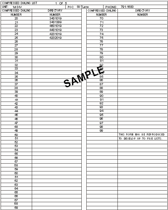
Figure 5-2. CDL
PREPROGRAMMED CONFERENCE LIST REQUIREMENTS |
|
5-54. Authorized PCL members can initiate a conference call with members of the PCL list (Figure 5-3). There can be a total of 20 PCLs numbered from 20 to 39, and each list can contain up to 14 subscribers. It is also possible to have four PCLs with a maximum of five subscribers each if there are enough bridge terminal cards in service at the switch. At the top of each list, YES or NO is circled to indicate whether security is required for the conference list. A YES entry requires a loop key generator (LKG) per instrument per call. Each DSVT/MSRT (whether security is circled YES or NO) requires an LKG per instrument per call. Therefore, the standard for programmed conferences should be DNVT telephone numbers and a security NO entry. Multiple conferences outside the standard will degrade service at the NCS. |
|
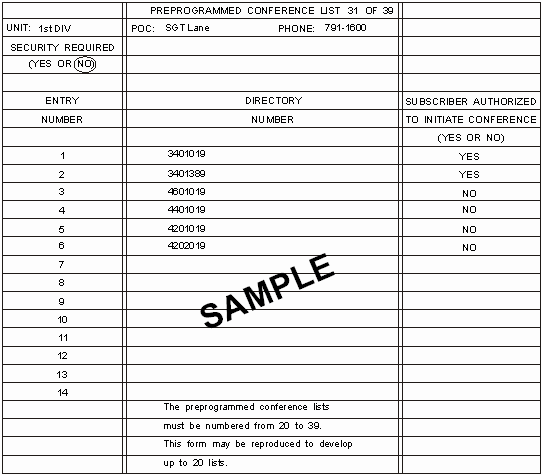
Figure 5-3. PCL
5-55. There are 20 corps common PCLs numbered 20 through 39. Only coordination with and aproval of the corps signal office can change these PCLs. Any temporary change for a particular exercise does not require a change to the tactical standing operating procedure (TSOP), but it does require a change to the tactical standing operating procedure (TSOP) but it does require updating a work sheet for that period. Table 5-7 shows an example of the corps PCL assignment. |
Table 5-7. Example of the Corps PCL Assignment
Preprogrammed Conference List |
Used For |
20 |
Corps Command |
22 |
Corps Administrative/ |
24 |
Corps Operations |
26 |
Corps Support Command |
28 |
Corps Reserved |
30 |
1st Division |
32 |
2d Division |
34 |
3d Division |
36 |
4th Division |
38 |
5th Division |
TEAM LABEL DATA FILE REQUIREMENTS |
|
5-56. The US Army Signal Center enters team label data into the team label data file (TLDF). The signal organization network manager or PAL manager for that database validates the TLDF. All teams are included in the TLDF. All MSE signal teams are assigned team labels according to the global team labeling scheme (Figure 5-4.) Table 5-8 shows the resulting corps standard team designation chart, which is used for team C2. Table 5-9 shows an example of the 1st Division's team labels. |
|
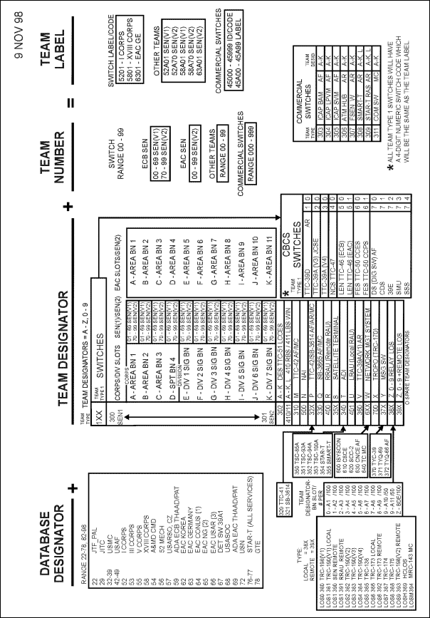
Figure 5-4. Global Team Labeling Scheme
Table 5-8. Corps Global Standard Team Designation Chart
| CORPS AREA SIGNAL BN TEAM LABELS AND SLOTS | DIVISION SIGNAL BN TEAM LABELS AND SLOTS |
DB01-DB09 DBA01 |
DB40-DB49 DBD01 |
Note: SENs are designated with a letter team designator (A-K). |
|
AREA BN SLOTS: |
DIVISION BN SLOTS: DBE01-DBE69 SEN(V1) DBD01 DBE70-DBE99 SEN(V2) DBF01-DBF69 SEN(V1) DBD02 DBF70-DBF99 SEN(V2) DBG01-DBG69 SEN(V1) DBD03 DBG70-DBG99 SEN(V2) DBH01-DBH99 SEN(V1) DBD04 DBH70-DBH99 SEN(V2) DBI01-DBI69 SEN(V1) DBD05 DBI70-DBI99 SEN(V2) DBJ01-DBJ69 SEN(V1) DBD06 DBJ70-DBJ99 SEN(V2) DBK01-DBK69 SEN(V1) DBD07 DBK70-DBK99 SEN(V2) |
|
Note: The LEN section is combined with the NCS section. |
|
|
Note: Remote radio access units (RRAUs) are designated with an R-Team designator, and local radio access units (LRAUs) are designated with a U-Team designator. |
|
| RRAU: DBR01-DBR09 DBA01 DBR10-DBR19 DBA02 DBR20-DBR29 DBA03 DBR30-DBR39 DBA04 LRAU: DBU01-DBU09 DBA01 DBU10-DBU19 DBA02 DBU20-DBU29 DBA03 DBU30-DBU39 DBA04 |
RRAU: DBR40-DBR49 DBD01 DBR50-DBR59 DBD02 DBR60-DBR69 DBD03 DBR70-DBR79 DBD04 DBR80-DBR89 DBD05 DBR90-DBR94 DBD06 DBR95-DBR99 DBD07 LRAU: DBU40-DBU49 DBD01 DBU50-DBU59 DBD02 DBU60-DBU69 DBD03 DBU70-DBU79 DBD04 DBU80-DBU89 DBD05 DBU90-DBU94 DBD06 DBU95-DBU99 DBD07 |
Note: Refer to the global team labeling scheme for details on the team labels for local LOSs. Both are designated with 0-9, Z-Team designators. |
|
Note: NATO interface teams, LOS(V2)s with NAI are designated with N-Team designators DBN01-DBN99. |
|
Note: Network management systems (SCC-2/ISYSCON, CSCE) are designated with a W-Team designator. |
|
Table 5-9. Example of the 1st Division's Team Labels
| Team Name | Team Label |
Team Label |
NCS |
DB40 |
DB42 |
Signal Support |
Company C |
|
LEN |
DB44 |
|
MSE FREQUENCY MANAGEMENT REQUIREMENTS |
|
5-57. MSE is the primary element of the ACUS, and its frequency management is an important task on the force-projection battlefield. However, it is only part of the total frequency management process. Both the CNR system and the ADDS also require frequency management support. These three systems are not mutually exclusive. The NPT provides an effective capability to manage the frequency spectrum for all three communications systems, while ensuring that the corps and its associated divisions can engage in a combat situation with minimum frequency interference. The NPT uses authorized frequencies obtained by the frequency manager to support VHF, UHF, and SHF spectrum requirements. The NPT tactical frequency assignment model (TACFAM) application develops frequency assignments for LOS radio links and performs link and site engineering and deconfliction based on selected parameters. Table 5-10 shows the number of MSE emitters in the corps AO. Table 5-11 shows the NPT frequency management capabilities. |
|
Table 5-10. Number of MSE Emitters
Element |
Number of MSE |
RAU |
736 |
Table 5-11. NPT Frequency Management Capabilities
Radio Equipment |
Frequency Assignment |
LOS Radio, AN/GRC-226(V) |
|
Radio, AN/GRC-224(P) |
|
Mobile Subscribers, RT-1539(P)/G |
|
| 5-58. The NPT VHF planning/management application uses the VHF input to develop the RAU/MSRT frequency plan. Coordination is then made with the system planner for distributing the frequency plan throughout the corps. The Revised Battlefield Electronics Communications-Electronics Operating Instructions (CEOI) System (RBECS) is the primary SOI management tool. |
FREQUENCY MANAGEMENT REQUIREMENTS |
|
| 5-59. The following paragraphs cover UHF parameters, SHF parameters, and LOS antenna polarization. | |
| UHF PARAMETERS | |
| 5-60. The UHF radio (AN/GRC-226) operates in two frequency bands. Band I is known as Band A and covers the frequency range from 225 to 400 MHz. Band III is known as Band B and covers the frequency range from 1350 to 1850 MHz. The SCC-2 system manager(s) select(s) the appropriate frequency band when preparing the open LOS radio link project. | |
| Signal-to-Interference Ratio | |
5-61. Table 5-12 provides AN/GRC-226 signal-to-interference ratios. This data represents operation at the highest (1,024 kbps) data rate. The data assumes a signal level at the terminal to the receiver unit at -88 dBm. Signal-to-interference ratios corresponding to various frequency separations between the received signal and the interference signal are given. The data applies to operation in either frequency Band I or III, respectively. |
|
Table 5-12. AN/GRC-226 Radio Signal-to-Interference Ratio
| Signal-to-Interference Frequency Spacing (MHz) |
Signal-to-Interference Radio Limitation1 |
0 | ±21 |
|
1 + Means signal power > interference power.- Means signal power < interference power. |
|
| Cable Loss Value | |
5-62. The following transmit and receive cable loss values represent the maximum attenuation for each of the two frequency bands.
5-63. If frequency scaling is used within the computer program, the following adjustment factors can be used:
5-64. Otherwise, the maximum values given above are used throughout the respective bands. |
|
| Receiver Sensitivity | |
5-65. The minimum receiver sensitivity for each of the two frequency bands is--
These values represent performance limits for the maximum data rate used. The maximum energy delivered by the transmitter for each of the two frequency bands is
|
|
| SHF PARAMETERS | |
5-66. The SHF radio AN/GRC-224(P) operates in a single frequency band. This band is 14,500 to 15,341 MHz and is divided into eight subbands. The subbands are paired to each other for the assignment of transmit and receive frequencies. The frequency manager selects the SHF frequency band when preparing the open LOS radio link project. Table 5-13 shows SHF and channel allocations for bands L and M. Band L is assigned to switches and Band M is assigned to LOS radio terminals. The following values characterize the performance of the SHF radio relative to the system communications margin computation.
|
|
| LOS ANTENNA POLARIZATION | |
5-67. The antennas can operate at either vertical or horizontal polarization. The NPT selects the antenna polarization for each LOS radio link by either an automatic or a manual mode. |
|
Table 5-13. SHF Bands L and M Frequency (in MHz) and Channel Allocations
Band L Channel Frequency |
Band M Channel Frequency |
|
01 14648.0 02 14651.5 03 14655.0 04 14658.5 05 14662.0 06 14665.5 07 14669.0 08 14672.5 09 14676.0 10 14679.5 11 14683.0 12 14686.5 13 14690.0 14 14693.5 15 14697.0 16 14700.5 17 14704.0 18 14707.5 19 14711.0 20 14714.5 21 14718.0 22 14721.5 23 14725.0 24 14728.5 25 14732.0 26 14735.5 27 14739.0 28 14742.5 29 14746.0 30 14749.5 31 14753.0 32 14756.5 33 14760.0 34 14763.5 35 14767.0 36 14770.5 37 14774.0 38 14777.5 39 14781.0 40 14784.5 41 14788.0 42 14791.5 43 14795.0 44 14798.5 45 14802.0 46 14805.5 47 14809.0 48 14812.5 49 14816.0 |
01 15033.0 02 15036.5 03 15040.0 04 15043.5 05 15047.0 06 15050.5 07 15054.0 08 15057.5 09 15061.0 10 15064.5 11 15068.0 12 15071.5 13 15075.0 14 15078.5 15 15082.0 16 15085.5 17 15089.0 18 15092.5 19 15096.0 20 15099.5 21 15103.0 22 15106.5 23 15110.0 24 15113.5 25 15117.0 26 15120.5 27 15124.0 28 15127.5 29 15131.0 30 15134.5 31 15138.0 32 15141.5 33 15145.0 34 15148.5 35 15152.0 36 15155.5 37 15159.0 38 15162.5 39 15166.0 40 15169.5 41 15173.0 42 15176.5 43 15180.0 44 15183.5 45 15187.0 46 15190.5 47 15194.0 48 15197.5 49 15201.0 |
Table 5-14. Estimated SHF radio signal-to-interference limitations
Signal-to-Interference Frequency Spacing (MHz) |
Signal-to-Interference Radio Limitation1 |
0 |
±21 |
| 1 + Means signal power > interference power. - Means signal power < interference power. |
|
|
NEWSLETTER
|
| Join the GlobalSecurity.org mailing list |
|
|
|

